Note : Les descriptions sont présentées dans la langue officielle dans laquelle elles ont été soumises.
CA 02244313 1998-07-28
D-20339
CRYOGENIC AIR SEPARATION WITH COMBINED
PREPURIFIER AND REGENERATORS
Field of the Invention
This invention relates to the cryogenic separation
5 of air wherein regenerators are used to cool feed air
prior to introducing the feed air into a cryogenic air
separation facility.
Backqround Art
Large scale commercial production of industrial
10 gases from the atmosphere generally involves cryogenic
processing of air. In addition to desired products
such as oxygen, nitrogen, argon and the rare gases, air
used as a starting material for cryogenic processing
(feed air) also contains impurities or undesirable
15 components such as water vapor, carbon dioxide and one
or more hydrocarbon species. These impurities must be
removed before processing of feed air can be completed
because the impurities interfere with continuous and
efficient operation of the cryogenic equipment, or may
20 present hazardous conditions which imperil the safety
of operators or damage equipment. A significant
portion of the cost of an air separation plant is
associated with cleaning or prepurifying air and with
cooling the air to cryogenic temperatures.
Various techniques have been used to provide air
separation systems with clean, low temperature air
streams. Heat exchangers allow simultaneous cooling of
CA 02244313 1998-07-28
D-20339
feed air and reheating of product streams. Feed air
and product streams flow in separate passages through
the heat exchanger. Early air separation systems
allowed impurities to deposit on the cold heat exchange
5 surfaces in the feed air passages, eventually causing
the heat exchanger to become plugged with condensed
impurity deposits or to become unable to cool the
incoming air to the required low temperature for
cryogenic separation. The plant would then be shut
10 down and thawed out. Later plants incorporated
chillers for the removal of part of the moisture, and
caustic scrubbers to remove carbon dioxide. As the
demand for gaseous products grew, devices known as
regenerators came into use to accomplish heat exchange
15 between feed air and product streams.
A regenerator comprises an insulated pressure
vessel filled with a packing material. The regenerator
is alternately heated and cooled by sequentially
passing a warm feed air stream followed by a cold
20 product stream through it. This differs from a heat
exchanger which has both heating and cooling streams
passing through it simultaneously. In a regenerator,
heat is retained by, or lost by, the walls and packing
material, which were in turn cooled or heated by the
25 previous stream of gas. The passage of feed air
through a regenerator removes the moisture and carbon
dioxide from the feed air as the air is cooled to near
saturation temperature. Operating regenerators in
pairs, alternating between the feed air and cold
CA 02244313 1998-07-28
D-20339
returning streams, allows the plant to continue
operating economically for up to a year. Such a system
is described in U.S. Patent No. 1, 945,634. When a cold
returning stream is warmed by passing through a
5 regenerator, the stream will mix with residual feed
air, and will also vaporize any impurities condensed in
the regenerator. If the stream is intended to be a
clean product, this results in contamination of product
with residual feed air and with impurities vaporized
10 into the stream. In order to avoid this, regenerators
are purged occasionally with a gas stream to vaporize
condensed impurities and sweep them out to the
atmosphere, thus wasting energy. U.S. Patent No.
2,825,212 describes use of adsorbents in the
15 regenerators to remove impurities from the feed air,
but this arrangement does not avoid the necessity for
frequent purging of the regenerators and adsorbents to
remove condensed impurities. To obtain clean products
without wasteful purging, coils are typically embedded
20 in the regenerators to provide a separate passage for
the high purity dry products without the opportunity
for contamination with feed air or condensed
impurities. However, such coils are known to fail due
to puncture, allowing contamination of product with
25 feed air, and are believed to accelerate particle
attrition.
Adsorption technology is now widely used to remove
the moisture, carbon dioxide and hydrocarbons from the
feed air stream. In many instances a chiller precedes
CA 02244313 1998-07-28
D-20339
the adsorption system to remove much of the moisture
and reduce the dehydration load on the adsorption
system. This system then provides a dried, and clean
air stream to the plant. Application of this method,
5 with molecular sieves being employed as the adsorbent
medium, is described in U.S. Patent No. 4,557,735.
This reference describes cooling compressed feed air
and then passing the cooled air through an adsorbent
material. This cooled air still needs to be cooled
10 further to cryogenic temperatures before it is fed to a
cryogenic separation system. This function, known as
primary heat exchange, is typically performed in brazed
aluminum heat exchangers (BAHX).
SUMMARY OF THE INVENTION
15 A method is provided for separation of air by
cryogenic rectification comprising compressing feed
air, passing the compressed feed air through a
prepurifier wherein the air is substantially cleaned of
impurities and cooling the cleaned air in a previously
20 cooled regenerator prior to introducing it into a
cryogenic air separation facility wherein it is
separated into nitrogen-rich and oxygen-rich
components. In a preferred embodiment of the
invention, a portion of the cleaned air is cooled in a
25 heat exchanger.
The capital cost of adsorbent prepurifiers
followed by BAHX cores is quite substantial. A process
employing regenerators with the use of prepurifiers
CA 02244313 1998-07-28
D-20339
provides several advantages over the presently used
system. The inefficiency incurred in passing air
through the regenerators to remove condensed impurities
is significantly reduced. In addition, no
5 refrigeration losses are incurred from condensing
impurities in the feed air. Perhaps more importantly,
the reliability and safety performance of prepurified
plants is increased over plants that use reversing heat
exchangers or regenerators to remove water and carbon
10 dioxide followed by cold adsorption of hydrocarbons.
In addition, the invention which removes
substantially all of the impurities from the air feed
to the plant with a prepurification system, eliminates
the need to design and operate the regenerators to also
15 remove cont~m'n~nts. This allows the equipment to be
optimized specifically to accomplish heat transfer
only, increasing its efficiency while decreasing
materials and operating costs and providing significant
economic advantages over current processes.
Even greater advantages may be achieved if the
product streams were passed through a BAHX, with the
regenerators being cooled only by waste streams as this
allows production of higher-purity product with fewer
operational problems.
BRIEF DESCRIPTION OF THE DRAWINGS
Figure 1 is a schematic representation of an
embodiment of the invention.
CA 02244313 1998-07-28
D-20339
Figure 2 is a schematic representation of a
preferred embodiment of the invention.
Figure 3 is a schematic representation of a
preferred embodiment of the invention wherein
5 partially cooled air from the heat exchanger is fed to
a turbine prior to separation.
Figure 4 is a schematic representation of a
preferred embodiment of the invention wherein
partially cooled air from a regenerator is fed to a
10 turbine prior to separation.
.Figure 5 is a schematic representation of a
preferred embodiment of the invention wherein a
booster compressor, a pressurizing pump, and a product
boiler are used to produce a high-pressure product
15 stream.
Figure 6 is a schematic representation of a
preferred embodiment of the invention wherein the
configuration has been altered to allow two product
streams.
DETAILED DESCRIPTION OF THE INVENTION
In the method of this invention, feed air
containing impurities such as water vapor, carbon
dioxide and hydrocarbons, is prepurified to
substantially remove all the impurities, and the
25 purified feed air is then cooled in regenerators.
Regenerators are designed more conveniently and
economically to cool prepurified feed air rather than
raw feed air. For example, regenerators operating on
CA 02244313 1998-07-28
D-20339
prepurified air streams can be made shorter than those
that process wet air, since they are not required to
perform a condensing duty.
In addition, self-cleaning cycles in which the
5 regenerators are purged of condensed impurities are
unnecessary. This eliminates the need to maintain
very small temperature differences along the
regenerator during operation to enable evaporation of
the condensed material during passage of the returning
10 non-product stream, henceforth termed the waste
stream. This greatly improves operability of
regenerators since there is no potential for blockage.
Elimination of the cleaning cycle also conserves
power. Because the air entering the regenerators is
15 dry, all of the air that is passed through the
regenerators may be passed from the regenerator cold
end and processed in the cryogenic separation system
to make product. None of the air need be sent out as
a waste stream due to contamination with condensed
20 impurities, a process referred to as blow down, thus
eliminating a major component of energy loss from the
process.
Further, since the streams processed by the
regenerators are clean, more choices of packing
25 material for the regenerators are available.
Traditional ceramic packing materials, such as quartz
gravel or alumina balls may be used. Other packing
materials can include metallic materials such as steel
or aluminum spheres. However, the absence of
CA 02244313 1998-07-28
D-20339
condensation and evaporation cycles in the method of
this invention reduces particle attrition, allowing
use of inexpensive, porous material, such as iron ore
pellets. An additional advantage of iron ore pellets
5 is their higher heat capacity relative to traditional
quartz gravel or alumina ball packings, which
increases the efficiency of the regenerators.
Generally the regenerators are upright cylindrical
vessels, but other vessel configurations are suitable.
Regenerators also enjoy a tremendous cost
advantage over brazed aluminum core heat exchangers.
Multiple parallel BAHX cores are often necessary to
handle large flows because there is a practical size
limitation on a single BAHX core imposed by the size of
15 the brazing furnaces available. Two regenerators
consisting of easily manufactured and relatively
inexpensive pressure vessels containing particulates
may replace multiple BAHX cores. The regenerators do
require switching valves and check valves, but these
20 can be externally insulated and the accompanying
pipework is simple, in contrast to the complex
manifolds and air trimming valves required on the feed
line to each BAHX core to control the air being passed
to them. The multiple BAHX cores needed to equal the
25 heat transfer capability of two regenerators would thus
require a much greater investment in piping and valves
in addition to the higher cost of the cores. Further,
these factors cause the lead time required for
CA 02244313 1998-07-28
D-20339
manufacture of BAHX cores to be significantly longer
than that for regenerators.
An embodiment of this invention is shown
schematically in Figure 1. Feed air delivered in
5 suction piping 60 is compressed in compressor 30 to an
operating pressure in the range from 40 to 200 psia,
preferably above 60 psia. The compressed air is then
aftercooled, preferably to a temperature in the range
from 1 to 40~C, and delivered to the prepurification
10 system 50 through piping 61. The prepurification
system may be any of the systems well known to the
industry. These may include but are not necessarily
limited to: chillers to reduce the dehumidification
load, alternating alumina beds for moisture removal in
15 combination with alternating molecular sieve beds to
remove the carbon dioxide and hydrocarbons. The
adsorbers may be regenerated by any of several well
known alternative methods. The prepurifier adsorbent
beds may be composed of a single adsorbent for all
20 cont~min~nts, a separate adsorbent for each
contaminant, or compound material beds. Further, the
prepurifier system can include single or multiple
vessels containing adsorbent material. Still further,
the prepurifier system can operate on the thermal
25 swing, pressure swing, or combined temperature and
pressure swing operating principle. The type of
prepurifier system is not limited for use in this
~ invention, as long as the prepurifier system performs
the task of removing the moisture, carbon dioxide, and
CA 022443l3 l998-07-28
D-20339
- 10
hydrocarbon contaminants in the feed air. Many
different prepurifier systems are well known in the
prior art.
The clean, dry air leaving prepurification system
5 50 in piping 62 iS then passed in piping 66 and 65 to
regenerators 2 and 4. Regenerator 2 iS fed clean, dry
air through automatic switching valve 102. Regenerator
2 including the packing or storage material therein
has been previously cooled by the passage therethrough
10 of the waste stream from the cryogenic air separation
facility 10. The clean air passing through cooled
regenerator 2 iS cooled to approximately its
saturation point. The saturated air will then either
pass through check valve 106, piping 68, 69, 71, and
15 72 to the cryogenic air separation facility 10 where
further cryogenic processing will accomplish the
separation of the air into its desired products, or
through check valve 106, piping 68, 69, 71, and 73 to
turbine 31 where it will be further cooled prior to
20 entering the separation plant 10 through piping 74.
Generally, the fraction of the feed aix that is
turboexpanded to develop plant refrigeration will
range from 5 to 20~ of the total feed air with 10 to
15~ as the preferred fraction. The cryogenic air
25 separation facility 10 is typically a double column
configuration as is well known in the art, but the may
also be a single column arrangement. Further, the
double column configuration can be any of the many
variations that are available in the art. The other
CA 02244313 1998-07-28
D-20339
regenerator 4 will be processing the cold waste stream
from separation plant 10 which will be cooling the
packing of regenerator 4 after passing through piping
77, 79 and check valve 107 at its cold end. The
5 packing or storage material of regenerator 4 holds the
refrigeration passed to it from the waste stream in
intermediate storage for the subsequent transfer to
clean feed air. The waste stream then leaves cooled
regenerator 4 through automatic switching valve 103
10 and is vented to the atmosphere through piping 81.
The product leaves the cryogenic air separation
facility through piping 75. Although product stream
75 is shown as exiting the cryogenic separation
facility 10 directly, it should be understood that
15 this product stream can be rewarmed versus a fraction
of the feed air. If the product stream 75 is in liquid
form, it can be recovered directly from the cryogenic
separation system. However, if the product stream 75
is a gaseous product, it can be rewarmed versus a
20 fraction of the feed air in either separate
regenerators, embedded coils in regenerators 2 and 4,
or in separate heat exchangers as will be described in
the following sections. Figure 1 illustrates only the
combined prepurifier and waste nitrogen regenerators
25 for purposes of clarity.
A disadvantage of conventional regenerators is
that, if a product stream passes through a
regenerator, it may be contaminated with residual feed
air. Isolation of the product stream in a separate
CA 022443l3 l998-07-28
D-20339
- 12 -
passage from that used for feed air can potentially
increase product purity. This has typically been
achieved by passing the product stream through
separate coils imbedded in the regenerator packing.
5 However, these coils often fail due to puncture,
allowing contamination of product. They are also
believed to accelerate attrition of the particulate
packing material in the regenerator. Alternatively
several regenerators may be used with each regenerator
10 seeing only one stream at any time. The difficulty
with this arrangement is that clean products will be
contaminated with air on flow reversal and valving
will tend to leak a little resulting in reduced
product purity.
In a preferred embodiment of this invention, the
problem of product contamination in the regenerators
has been solved by heating only the waste stream in the
regenerators. In this embodiment, the product stream
is typically warmed in BAHX cores. Preferably, the
20 feed air is split between the regenerators and the BAHX
to balance the temperature profile in both. The
fraction passing through the regenerators is preferably
40 to 80 per cent, and most preferably about 60 to 80
per cent. Thus, this arrangement maintains the
25 flexibility of using the cores, which readily handle
multiple streams, and isolate product from feed air,
while having a significant portion of the heat exchange
accomplished using the more cost-effective
regenerators. Another advantage of this arrangement is
CA 02244313 1998-07-28
D-20339
that, because the regenerators are not designed with
separate coils to provide clean passages for product
streams, it is possible to fill the vessels with large
structured fill (monolith). Such fill may comprise,
5 for example, of corrugated sheets. Such packings
provide a higher heat transfer rate for a given
pressure drop. This also allows the cross sectional
area of the vessels to be decreased.
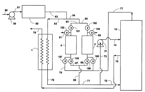
A preferred embodiment of this invention is shown
10 schematically in Figure 2. Feed air delivered in
suction piping 60 is compressed in compressor 30 to an
operating pressure in the range from 40 to 200 psia,
preferably above 60 psia. The compressed air is then
aftercooled, preferably to a temperature in the range
15 from 1~C to 40~C, and delivered to the prepurification
system 50 through piping 61. The clean, dry air
leaving prepurification system 50 in piping 62 is then
split into two portions, one being passed in piping 64
to regenerators 2 and 4 and the remainder passing to
20 primary heat exchanger 1 through piping 63.
Regenerator 2 is fed clean, dry air through piping 66
and automatic switching valve 102, the packing of
regenerator 2 having been previously cooled by the
waste stream from the cryogenic separation facility 10,
25 thus cooling the incoming clean air to approximately
its saturation point. The saturated air is then either
passed through check valve 106, piping 68, 69, 71, and
72 to the cryogenic separation section 10 where further
cryogenic processing will accomplish the separation of
CA 022443l3 l998-07-28
D-20339
- 14 -
the air into its desired products, or through check
valve 106, piping 68, 69, 71, and 73 to turbine 31
where it will be further cooled prior to entering the
separation plant 10 through piping 74. The other
5 regenerator 4 will be processing the cold waste stream
from separation plant 10 which will be cooling the
packing of regenerator 4 after passing through piping
77, 79 and check valve 107 at its cold end. The waste
stream then leaves regenerator 4 through automatic
10 switching valve 103 at its warm end and is vented to
the atmosphere through piping 81.
The remainder of the clean, dry air from the
prepurification system 50 and piping 62 iS passed
through piping 63 to primary heat exchanger 1 where it
15 is balanced against the product stream leaving
cryogenic separation facility 10 in piping 75 through
primary heat exchanger 1 and warm end piping 76 in a
continuous manner. The split of the feed air between
the regenerators and the primary heat exchanger is
20 determined by the relative flows of the product stream
and the waste stream.
Figures 3, 4, 5, and 6 illustrate other preferred
embodiments of the invention. The numerals in these
figures correspond to those in Figures 1 and 2 for all
25 common elements and these elements will not be
described again in detail.
Modern turbines have been shown to operate with
high efficiencies with air that is essentially
saturated. Figure 1 shows the turbine being fed from
CA 02244313 1998-07-28
D-20339
the cold end of the regenerator. However, this scheme
is not limited to this type of turbine feed. A side
bleed of air may easily be withdrawn from a heat
exchanger or a regenerator, allowing the cold and warm
5 end temperatures to approach each other closely. This
midpoint air may serve as a turbine feed. If it is
desired to use preheat from a heat exchanger for the
turbine feed, this is provided in another embodiment of
this invention, as shown in Figure 3. Partially-cooled
10 air is withdrawn from the midpoint of primary heat
exchanger 1, through piping 82, blended with a portion
of the cold end air, from piping 83, for temperature
control, and then passed to turbine 31 via piping 73.
The air is then cooled by the turbine prior to entering
15 the cryogenic separation section 10.
Figure 4 illustrates an embodiment of this
invention in which turbine preheat is provided by
withdrawing air from regenerator 2 at its midpoint
through piping 85 and feeding it to turbine 31 through
20 piping 86 and 87. Temperature control may be obtained
by blending this air with regenerator cold end air fed
to the turbine through valve 106, piping 68, 69, 71,
73, and 87. When regenerator 4 is being used to cool
prepurified feed air, the preheat stream is withdrawn
25 through piping 84 instead of piping 85.
This invention is also applicable to use of a
product boiler to deliver product at an elevated
pressure. This embodiment of the invention is shown in
Figure 5. In this case liquid oxygen is withdrawn from
CA 022443l3 l998-07-28
D-20339
- 16 -
the main condenser of the cryogenic separation plant in
piping 75 and is pressurized by pump 32. Although the
process is not limited to any pumped liquid pressure
level, typical liquid pressure levels range from 20
5 psia to 500 psia, with preferred levels of 50 psia to
250 psia. The pressurized liquid oxygen passes through
piping 88 and is then vaporized in product boiler 3
against cold end air from primary heat exchanger 1. A
portion of the prepurified air passes through piping
10 92, iS raised in pressure by booster compressor 33, and
then is processed in primary heat exchanger 1 to
provide the heat necessary in product boiler 3 to
vaporize the liquid oxygen. The feed air used to
vaporize the pressurized liquid oxygen will correspond
15 in flow and pressure to the flow and pressure of the
product stream. Generally, the feed air flow will be
about 1. 2 times the quantity of the product flow. The
feed air pressure level will be above the pressure
level of the product to allow cooling and condensation
20 of the air feed versus the vaporizing product.
Generally, the feed air pressure level will range from
about 50 psia to about 1000 psia, with a preferred
level of from about 100 psia to about 500 psia. The
vaporized oxygen is passed through piping 89 and then
25 warmed in primary heat exchanger 1 for delivery to the
consumer via piping 76.
This invention, in another embodiment, provides
more than one clean product. An example of this
embodiment is shown in Figure 6 where both a clean
CA 02244313 1998-07-28
D-20339
oxygen product and a clean nitrogen product are
produced. The nitrogen product stream leaves the
cryogenic separation section in piping 92. Both clean
product streams are passed through primary heat
5 exchanger 1 in separate channels, the nitrogen exiting
through piping 93 and the oxygen through piping 76.
The two streams are balanced thermodynamically with the
corresponding flow of feed air. The remaining feed air
thus balances the waste stream in the regenerators.
10 This provides flexibility in the application of this
invention. As in all other preferred embodiments of
this invention, the waste stream 77 is heated solely in
the regenerators.
The method of this invention is not limited to
15 operation with pairs of regenerators as shown in the
preferred embodiments, but is equally operational with
triplets of regenerators, or any other number of
regenerators determined to be economical because of
pressure drop, temperature differences, vessel or
20 packing cost or valving and manifolding.