Sélection de la langue

Search

Sommaire du brevet 2247153 

Énoncé de désistement de responsabilité concernant l'information provenant de tiers

Une partie des informations de ce site Web a été fournie par des sources externes. Le gouvernement du Canada n'assume aucune responsabilité concernant la précision, l'actualité ou la fiabilité des informations fournies par les sources externes. Les utilisateurs qui désirent employer cette information devraient consulter directement la source des informations. Le contenu fourni par les sources externes n'est pas assujetti aux exigences sur les langues officielles, la protection des renseignements personnels et l'accessibilité.

Disponibilité de l'Abrégé et des Revendications

L'apparition de différences dans le texte et l'image des Revendications et de l'Abrégé dépend du moment auquel le document est publié. Les textes des Revendications et de l'Abrégé sont affichés :

  • lorsque la demande peut être examinée par le public;
  • lorsque le brevet est émis (délivrance).
(12) Brevet: (11) CA 2247153
(54) Titre français: AMENAGEMENT DE LA BUSE ET DU RECEPTACLE DU VENTILATEUR
(54) Titre anglais: FAN SHROUD AND RECEPTACLE ARRANGEMENT
Statut: Réputé périmé
Données bibliographiques
(51) Classification internationale des brevets (CIB):
  • F04D 29/60 (2006.01)
  • F01P 3/00 (2006.01)
  • F01P 5/06 (2006.01)
  • F01P 11/02 (2006.01)
  • F04D 29/40 (2006.01)
  • F04D 29/54 (2006.01)
  • F28F 9/00 (2006.01)
(72) Inventeurs :
  • PLANT, WILLIAM D. (Etats-Unis d'Amérique)
(73) Titulaires :
  • MCCORD WINN TEXTRON INC. (Etats-Unis d'Amérique)
(71) Demandeurs :
  • MCCORD WINN TEXTRON INC. (Etats-Unis d'Amérique)
(74) Agent: MACRAE & CO.
(74) Co-agent:
(45) Délivré: 2005-05-10
(86) Date de dépôt PCT: 1997-01-29
(87) Mise à la disponibilité du public: 1997-08-28
Requête d'examen: 2002-01-03
Licence disponible: S.O.
(25) Langue des documents déposés: Anglais

Traité de coopération en matière de brevets (PCT): Oui
(86) Numéro de la demande PCT: PCT/US1997/001390
(87) Numéro de publication internationale PCT: WO1997/031182
(85) Entrée nationale: 1998-08-21

(30) Données de priorité de la demande:
Numéro de la demande Pays / territoire Date
605,981 Etats-Unis d'Amérique 1996-02-23

Abrégés

Abrégé français

L'aménagement de la buse et du réceptacle du ventilateur se fait à proximité du radiateur (12) d'un véhicule et autour du ventilateur ou des ventilateurs (14) du moteur. L'ensemble inclue un corps creux modelé (18) d'une profondeur prédéterminée et possédant une partie avant (24), une partie arrière (26), des parois supérieure (28) et inférieure (30), des parois latérales (34 et 34) opposées l'une à l'autre, au moins une ouverture (20) pratiquée dans le corps (18) et limitée par une paroi cylindrique (22 ou 23). Des enfoncements opposés l'un à l'autre (50 et 52) sont pratiqués dans les parois avant et arrière (24 et 26) pour former une paroi (54) qui partage le corps creux (18) en deux ou plusieurs chambres intérieures (44 et 46). Des goulots de remplissage (40 et 42) et/ou d'autres ouvertures sont pratiquées dans la paroi supérieure (28) afin de pouvoir communiquer avec deux ou plusieurs chambres intérieures (44 et 46).


Abrégé anglais


A fan shroud and receptacle arrangement for use adjacent a vehicle radiator
(12) and around one or more engine cooling fans (14).
The arrangement includes a shaped hollow body (18) of a predetermined depth
and having a front face (24), a rear face (26), a top wall (28),
a bottom wall (30), oppositely disposed side walls (32 and 34), at least one
opening (20) formed through the body (18) with a cylindrical
wall (22 or 23) therearound. Oppositely disposed recesses (50 and 52) are
formed in the front and rear faces (24 and 26) to form a wall
(54) for dividing the hollow body (18) into two or more internal chambers (44
and 46). Filler necks (40 and 42) and/or other openings are
formed in the top wall (28) for communicating with the two or more internal
chambers (44 and 46).

Revendications

Note : Les revendications sont présentées dans la langue officielle dans laquelle elles ont été soumises.


9

CLAIMS

1. A fan shroud and receptacle arrangement
for use adjacent a vehicle radiator and around one or
more engine cooling fans, the arrangement comprising a
shaped hollow body of a predetermined depth and having
to a front face, a rear face spaced from said front face,
a top wall, a bottom wall, oppositely disposed side
walls, at least one opening formed through the body of
a size to accommodate air flow through the vehicle
radiator and having a cylindrical wall therearound, at
least one set of oppositely disposed recesses formed in
the front and rear faces to form a wall for dividing
the hollow body into two or more internal chambers, and
openings formed in the body for communicating with the
two or more internal chambers.

2. The fan shroud and receptacle arrangement
described in claim 1, wherein the wall for dividing the
hollow body into two or more internal chambers is
formed above and below the cylindrical wall.

3. The fan shroud and receptacle arrangement
described in claim 2, including two openings having
cylindrical walls therearound.

4. The fan shroud and receptacle arrangement
described in claim 3, wherein one chamber completely
surrounds one cylindrical wall.

5. The fan shroud and receptacle arrangement
described in claim 1, and mounting tabs integrally
formed on oppositely disposed sides of said at least


10


one opening adapted to receive a fan assembly mounting
bracket.
6. The fan shroud and receptacle arrangement
described in claim 1, wherein the hollow body is formed
by blow molding.
7. The fan shroud and receptacle arrangement
described in claim 6, and a frame structure adapted to
support a fan motor and integrally formed on the hollow
body during the blow molding.

Description

Note : Les descriptions sont présentées dans la langue officielle dans laquelle elles ont été soumises.


CA 02247153 1998-08-21
WO 97!31182 PCT/US97/01390
i
fAN SHROUD AND RECEPTACIrE ARRANGEMENT
' field of the Disclosure
' S This invention relates generally to automotive
radiator fan shrouds and, more particularly to such
shrouds which are blow molded to include hollow
compartments which serve as reservoirs for fluids, such
as coolant fluid, and/or window and headlamp washer
fluids, including air and other gases.
8aakaraund Art
Tangue et al patent no. 3,692,004 discloses a
fan shroud and fluid receptacle arrangement including a
cylindrical band or collar extending away from a
radiator, and a radiator fluid receptacle and a
windshield washer fluid receptacle integrally molded on
opposite side surfaces of the cylindrical band or
collar.
Two patents Which disclose blow molded
radiators are Gross et al nos. 3,833,054 and 4,030,541.
Patents disclosing plastic radiators or
associated parts thereof include Bly no. 4,709,757;
Ziegler no. 4,762,244; Temmesfeld et al no. 4,763,724;
Vitacco no. 4,947,931; and Herbert et al no. 5,107,924.
Summarv Of The Invention
r
A general object of the invention is to
provide an improved, compact and efficient blow molded
radiator fan shrouds with integral fluid receptacles.


CA 02247153 1998-08-21
WO 97/31182 PCT/LTS97/01390
2
Another object of the invention is to provide
a one-piece fan shroud arrangement wherein compartments,
such as a radiator fluid overflow compartment, a
windshield washer fluid compartment, and a headlamp
washer fluid compartment, are integrally contained '
around side surfaces of at least one fan shroud formed
as openings through a blow molded receptacle.
Another object of the invention is to provide
a compact, one-piece fan shroud and dual fluid
receptacle arrangement, resulting in: (1) the
elimination of the need for space and fastening means
for three separate components; (2) cost savings by
virtue of having eliminated the need to manufacture
three separate parts, while utilizing heretofore unused
surrounding surface areas of the fan shroud; (3) the
possible elimination of the need for retooling for
different designs for specific vehicle models;, (4)
larger capacity windshield washer fluid and/or headlamp
washer fluid compartments; (5) a radially and axially
rigid structure; and (6) improved aerodynamic surface
areas around the fan opening to allow higher, more
efficient air flow through the fan shroud and receptacle
assembly.
These and other objects and advantages of the
invention will become apparent when reference is made to
the following drawings and the accompanying description.
Brief Description Of The Draw nas
1
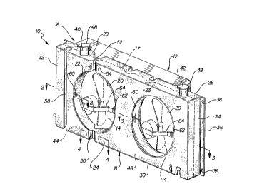
Figure 1 illustrates a perspective view of a
blow molded fan shroud embodying the invention;


CA 02247153 1998-08-21
WO 97/31182 PCT/US97/01390
3
Figures 2, 3 and 4 are cross-sectional views
taken along the planes of the lines 2-2, 3-3, and 4-4,
respectively, of Figure 1, and looking in the directions
of the arrows; and
' 5 Figure 5 is a perspective view of an alternate
embodiment of the invention.
Hest Mode For Carrvinq The Iaventi.on
Referring now to the drawings in greater
detail, Figure 1 illustrates an automotive engine
cooling system 10, including a radiator 12, two engine
cooling fans 14 shown in phantom, and a blow molded fan
shroud arrangement 16. The latter arrangement 16 is
blow molded (the mold parting line 17 is shown in
phantom) to include a rectangular hollow body Z8 of
predetermined height, width and depth, and having dual
openings 20 with respective cylindrical walls 22 and 23
formed therethrough and adapted to surround the outer
peripheral paths of the two fans 14.
More specifically, the body 18 includes a
front face 24, a rear face 26, a top wall 28, a bottom
wall 30, and oppositely disposed side walls 32 and 34.
A flange or tab 36 is formed on an edge of
each side wall 32 and 34. The flanges 36 include spaced
mounting holes 38 adapted to accommodate fasteners 39 to
mount the body 18 on the radiator 12 of the vehicle
involved, as shown in Figure 3.
A pair of filler necks 40 and 42 are formed at
spaced-apart locations along the top wall 28, for
communicating with respective chambers 44 and 46 formed


CA 02247153 1998-08-21
WO 97/31182 PCT/US97/0I390
4
within the hollow body 18, adjacent and around the
cylindrical walls 22, as will be explained. A pair of
removable caps 48 are mounted on the filler necks 40 and
42.
Oppositely disposed vertically oriented
recesses 50 and 52 are formed in the respective front
and rear faces 24 and 26 to provide walls 54 (Figure 1)
and 56 (Figure 4) adjacent upper and lower portions of
the cylindrical wall 22, serving to separate the
chambers 44 and 46.
Additional recesses, such as the vertical
recess 58 (Figures 1 and 2), may be formed in the front
face 24 to accommodate wire harnesses, hoses, or the
like.
Perforated tabs 60 and 62 are formed on
opposite edges of each opening 20 to accommodate the
mounting of fan assembly support brackets 64, as shown
in Figures 2 and 3. A U-nut clip 66 is mounted around
each tab 6o and 62, and a fastener 68 is mounted through
aligned holes 70 formed in the clip 66 and each tab 60
and 62.
As shown in Figure 3, a fan motor 72 is
secured by suitable fasteners 74 to the inner surface of
a U-shaped portion 76 of the support bracket 64.
The chamber 44 is enclosed by the front and
rear faces 24 and 26, the top wall 28, the side wall 32,
the bottom wall 30, the walls of the recesses 50 and 52
adjacent the lower recessed wall 56 (Figure 4), the ,
cylindrical wall 22 (Figure 2), and the walls of the


CA 02247153 1998-08-21
WO 97/31182 PCTJUS97/01390
recesses 50 and 52 adjacent the upper recessed wall 54
(Figure 1).
The chamber 46 encompasses a larger volume
5 than the chamber 44, and is enclosed by the front and
rear faces 24 and 26, top wall 28, the side wall 34, the
bottom wall 30, the walls of the recesses 50 and 52
adjacent the lower separating recessed wall 56 (Figure
4), the cylindrical wall 22, and the walls of the
l0 recesses 50 and 52 adjacent the upper separating
recessed wall 54, while completely surrounding the
cylindrical wall 23.
As represented in phantom in Figure 4, the
mold 80 design incorporates "tacks offs" to separate the
chambers 44 and 46 in the molding process.
As shown in Figure 5, in lieu of the
separately attached fan assembly mounting bracket 64
2o shown in Figure 3, an integral frame structure 82 may be
compression molded during the blow molding process.
Industrial Apaalicabiiitv
It should be apparent that the invention
provides a compact cooling system structure which
eliminates the need for space and fastening means for
three separate components in the already crowded engine
compartment of today's automobile. It provides
substantial cost savings by virtue of having eliminated
the need to manufacture and assemble three separate
parts, while utilizing heretofore unused surface areas
of the fan shroud.


CA 02247153 1998-08-21
W~ 97/31182 PCT/US97l01390
6
Additionally, the invention may provide a
standard or uniform structure which is unaffected by
many new vehicular designs. Specifically, the shape of
the compartments 44 and 46 need not be redesigned each
time the fender wells and other interior parts are
changed on at least some new vehicle models. Also, the
integrally molded windshield washer fluid or headlamp
washer fluid. compartments may have a larger capacity
than the previously employed separate containers.
Furthermore, the resultant structure is
extremely rigid, both radially and axially, and damped
by fluid in the receptacles, reducing vibration or
excitation of the fan shroud caused by the rotating fan
surrounded thereby, hence diminishing a possible source
of bothersome noise.
It should be further apparent that the
inventive fan shroud and receptacle arrangement could be
formed by one-piece gas assist injection molding, as
well as by blow molding.
It should be still further apparent that, in
lieu of the integral frame structure 82 of Figure 5, and
the separately attached fan assembly mounting bracket 64
and tabs 60 and 62 of Figure 3, the openings 20 are
adaptable to having fans mounted therein which are belt-
driven and attached to the motor.
While but one embodiment of the invention has
been shown and described, other modifications thereof
are possible within the scope of the following claims.

Dessin représentatif
Une figure unique qui représente un dessin illustrant l'invention.
États administratifs

Pour une meilleure compréhension de l'état de la demande ou brevet qui figure sur cette page, la rubrique Mise en garde , et les descriptions de Brevet , États administratifs , Taxes périodiques et Historique des paiements devraient être consultées.

États administratifs

Titre Date
Date de délivrance prévu 2005-05-10
(86) Date de dépôt PCT 1997-01-29
(87) Date de publication PCT 1997-08-28
(85) Entrée nationale 1998-08-21
Requête d'examen 2002-01-03
(45) Délivré 2005-05-10
Réputé périmé 2007-01-29

Historique d'abandonnement

Il n'y a pas d'historique d'abandonnement

Historique des paiements

Type de taxes Anniversaire Échéance Montant payé Date payée
Le dépôt d'une demande de brevet 300,00 $ 1998-08-21
Enregistrement de documents 100,00 $ 1998-12-09
Taxe de maintien en état - Demande - nouvelle loi 2 1999-01-29 100,00 $ 1999-01-28
Taxe de maintien en état - Demande - nouvelle loi 3 2000-01-31 100,00 $ 2000-01-07
Taxe de maintien en état - Demande - nouvelle loi 4 2001-01-29 100,00 $ 2001-01-04
Requête d'examen 400,00 $ 2002-01-03
Taxe de maintien en état - Demande - nouvelle loi 5 2002-01-29 150,00 $ 2002-01-07
Taxe de maintien en état - Demande - nouvelle loi 6 2003-01-29 150,00 $ 2002-12-27
Taxe de maintien en état - Demande - nouvelle loi 7 2004-01-29 200,00 $ 2004-01-22
Taxe finale 300,00 $ 2004-11-15
Taxe de maintien en état - Demande - nouvelle loi 8 2005-01-31 200,00 $ 2005-01-31
Titulaires au dossier

Les titulaires actuels et antérieures au dossier sont affichés en ordre alphabétique.

Titulaires actuels au dossier
MCCORD WINN TEXTRON INC.
Titulaires antérieures au dossier
PLANT, WILLIAM D.
Les propriétaires antérieurs qui ne figurent pas dans la liste des « Propriétaires au dossier » apparaîtront dans d'autres documents au dossier.
Documents

Pour visionner les fichiers sélectionnés, entrer le code reCAPTCHA :


Pour visualiser une image, cliquer sur un lien dans la colonne description du document. Pour télécharger l'image (les images), cliquer l'une ou plusieurs cases à cocher dans la première colonne et ensuite cliquer sur le bouton "Télécharger sélection en format PDF (archive Zip)" ou le bouton "Télécharger sélection (en un fichier PDF fusionné)".

Liste des documents de brevet publiés et non publiés sur la BDBC .

Si vous avez des difficultés à accéder au contenu, veuillez communiquer avec le Centre de services à la clientèle au 1-866-997-1936, ou envoyer un courriel au Centre de service à la clientèle de l'OPIC.


Description du
Document 
Date
(yyyy-mm-dd) 
Nombre de pages   Taille de l'image (Ko) 
Dessins représentatifs 1998-11-19 1 20
Dessins 1998-08-21 3 107
Abrégé 1998-08-21 1 58
Description 1998-08-21 6 229
Revendications 1998-08-21 2 53
Page couverture 1998-11-19 1 65
Page couverture 2005-04-13 1 54
Cession 1998-12-09 6 268
Correspondance 1998-11-03 1 31
PCT 1998-08-21 9 298
Cession 1998-08-21 3 96
Poursuite-Amendment 2002-01-03 1 32
Poursuite-Amendment 2002-04-18 1 32
Correspondance 2004-11-15 1 32
Poursuite-Amendment 2005-02-02 1 45
Taxes 2005-01-31 1 24