Note : Les descriptions sont présentées dans la langue officielle dans laquelle elles ont été soumises.
CA 02247864 1998-08-28
WO 97/31872 PCT/US97/02826
I
~1(RAT TEMPER_ABLE TR_ANSPAI~ENT COATED GLASS ARTI('T F
FIELD F THE INVENTION
This invention is directed to transparent coatings for glass substrates, and
particularly to glass substrates having coatings that are capable of
withstanding high
temperatures such as those encountered during glass tempering and bending.
BACKGROUND OF THE INVENTION
Glass sheets can be coated with a stack of transparent, metal-containing films
to
vary the optical properties of the coated sheets. Particularly desirable are
coatings
characterized by their ability to readily transmit visible light while
minimizing the
transmittance of other wavelengths of light, particularly light in the
infrared spectrum.
These characteristics are useful for minimizing radiative heat transfer
without impairing
visibility, and coated glass of this type is useful as architectural glass,
glass for use as
automobile Windows, etc.
Coatings having the characteristics of high transmittance and low emissivity
commonly include film stacks having one or more thin metallic films with high
infrared
reflectance that are disposed between antireflective dielectric films such as
metal oxide
films. The metallic films may be silver, and the metal oxide films may be the
oxides of
various metals and metal alloys including zinc, tin, titanium, etc. Films of
the type
described commonly are deposited on glass substrates on a commercial
production basis
through the use of well known magnetron sputtering techniques.
It is often necessary to heat glass sheets to temperatures at or near the
melting
paint of the glass to temper the glass or to enable the glass to be bent into
desired shapes
such as motor vehicle windshields. Coated glass articles often must be able to
withstand
high temperatures for periods of time up to several hours. Tempering, as is
known, is
particularly important for glass intended for use as automobile windshields;
upon
breaking, windshields desirably exhibit a break pattern in which they shatter
into a great
many small pieces rather than into Large, dangerous sharp shards. Temperatures
on the
order of 600°C and above are required. Film stacks employing silver as
an infrared
reflective film often cannot withstand such temperatures without deterioration
of the
silver film. To avoid this problem, glass sheets can be heated and bent or
tempered
before they are coated, and later can be provided with the desired metal and
metal oxide
CA 02247864 1998-08-28
WO 97/31872 PCTlUS97/02826
2
coatings. Particularly for bent glass articles, this procedure usually
produces non-
uniform coatings and is costly.
Another reported method for protecting a reflective metal film from
deterioration
at high temperatures involves sandwiching the silver film between protective
films of an
oxidizable metal such as titanium, these protective metal filins being of
sufficient
thickness so that when a coated glass is heated to high temperatures, the
protective metal
films oxidize. Inasmuch as the oxides of metals commonly are more transparent
than
the metals themselves, the transmissivity of glass sheets bearing such
coatings tends to
increase upon heating. Reference is made to Huffer et al. U.S. patent
4,790,922 and
Finley U.S. patent 4,806,220.
U.S. patent 5,344,718 (Hartig et al.) describes the use of a fllm stack in
which
silver is sandwiched between films of nickel or nichrome, and the resulting
sandwich is
sandwiched between films of Si3N4, the glass article having particular values
of
transmittance and emissivity. It is said that when a Ni:Cr (50:50) alloy is
employed, the
Cr during sputtering is converted at least in part to a nitride of Cr and that
visible
transmittance thus is improved. The ability of nickel, chromium and chromium
nitride
to transmit visible Light, however, is not great, and as a result the
transmissivity of glass
articles that include films of nichrome may be somewhat less than desired.
SUMMAIRY OF THE INVENTION
The invention in one embodiment relates to a highly desirable heat-resistant
glass
product that can be manufactured by creating a film stack on glass in which an
infrared
reflective film such as silver is sandwiched between thin, protective films of
a metal or
semiconductor such as silicon, and the resulting structure is sandwiched
between films
of a nitride such as silicon nitride, so that one or both of the protective
films contain an
element that is also contained in one or both of the nitride films. The
preferred element
that the protective films and the nitride films have in common is silicon.
When glass
articles containing the film stack of the invention are heated to high
temperatures such as
temperatures of 600° or above, as, for example, in the 700°C to
750°C range,
transmissivity of the glass article to visible light may increase slightly.
The thicknesses of the protective films are chosen so that adhesion to the
infrared
reflective layer is not unduly diminished by the heat treatment. Without being
bound by
the following explanation, it appears that nitrogen from the nitride films,
particularly the
CA 02247864 2002-08-26
outer nitride film, adjacent to the thin, protective films, liberate nitrogen
when raised to
heat tempering temperatures, and that the nitrogen so released combines to
form a
nitride with the protective films. Some oxidation of the outer protective film
may occur
also. In this manner, the protective films serve to protect the infrared
reflective metal
film from becoming nitride or oxidized.
When silicon is employed for the protective films, it appears that the
protective
films are at least partially converted to silicon nitride. Silicon nitride is
more transparent
than is elemental silicon, and as a result the tranmissivity of the entire
glass article is
improved if in fact the transmissivity is changed at all by high temperature
exposure.
Moreover, since an elemental component (e.g., silicon) of both the nitride
films and the
protective films are the same, sharp interfaces between the protective film
and the
nitride films are more likely to be avoided, leading to greater stack
homogeneity and
reducing the likelihood of failure due to separation of the nitride from the
protective
film. However, if the protective films comprise silicon and the silicon-
containing films
are too thin, then the durability of the film stack often is reduced. The
silicon-containing
layers, and particularly the protective film upon the reflective layer, are
deposited at
thickness such that the film stack can withstand high temperature processing
while
maintaining good durability, and it appears that this phenomena is due to the
retention of
unreacted silicon metal on both sides of the infrared reflective layer.
In an alternative embodiment, the nitride films are replaced with oxide films.
For
example, such a film could comprise silver sandwiched between thin, protective
layers
of a metal or semiconductor such as silicon, with that structure sandwiched
between
layers of an oxide of a metal or semiconductor such as an oxide of silicon
(e.g. Si02) or,
less desirably, an oxide of titanium (TiOX). Although these types of film
stacks may
yield a marginally suitable film stack, the above embodiment wherein nitrides,
rather
than oxides, are used is preferred.
In accordance with one aspect of the present invention there is provided a
transparent heat-resistant glass article comprising a glass substrate and a
transparent film
stack deposited upon the substrate, said film stack including, from the glass
substrate
outwardly, a transparent silicon nitride film, a flm of elemental silicon, a
transparent
infrared reflective silver-containing metallic film, a film of elemental
silicon, and a
transparent silicon nitride film.
CA 02247864 2002-08-26
3a
In accordance with another aspect of the present invention there is provided a
transparent heat-resistant glass article comprising a glass substrate and a
transparent film
stack deposited upon the substrate, said film stack comprising, from the glass
substrate
outwardly, a transparent silicon nitride film having a thickness of from 250
~r to 500 A,
a first protective film of elemental silicon, a transparent infrared
reflective silver-
containing metallic film, a second protective film of elemental silicon, and a
transparent
silicon nitride film having a thickness of 350 ~ to 600 !~.
In accordance with yet another aspect of the present invention there is
provided a
method for manufacturing a heat treated transparent glass article comprising
the steps of
depositing on a surface of the glass article a transparent film stack
including, from the
glass substrate outwardly, a first transparent nitride film, an elemental
silicon second
film, a transparent infrared reflective metallic third film, an elemental
silicon fourth
film, and a fifth transparent nitride film, wherein at least one of said
nitride films
comprises silicon nitride; and heating said coated article.
BRIEF DESCRIPTION OF THE DRAWINGS
An embodiment of the present invention will now be described more fully with
reference to the accompanying drawings in which:
Figure 1 is a cross-sectional, schematic view of a film stack of the
invention; and
Figure 2 is a cross-sectional, schematic view of a modified version of the
film
_~__,_ _rr:_____
30
CA 02247864 2002-08-26
4
DETAILED DESCRIPTION OF THE PREFERRED EMBODIMENTS
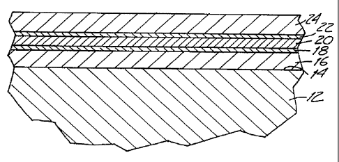
Referring to the film stack shown in Figure 1, a glass sheet is shown as 12.
Upon its surface 14 is deposited, in sequence, a nitride film 16, a thin
protective film
18, an infrared reflective metallic film 20, a thin, protective film 22, and a
nitride film
24. It will be understood that the thicknesses of the various films in the
drawing are not
to scale.
The individual films of the film stack of the invention may be deposited upon
the
glass substrate 12 by any convenient means. A preferred deposition method
involves
D.C. magnetron sputtering, as described in Chapin U.S. Patent No. 4,166,018.
Magnetron sputtering deposition involves transporting a glass substrate
through a series
of low pressure zones in which the various films that make up the film stack
are
sequentially applied. Metallic films are sputtered from metallic sources or
"targets". A
metal film may be formed by sputtering from a metal target in an inert gas
atmosphere
such as argon, whereas a nitride film such as silicon nitride may be sputtered
utilizing a
silicon target in a reactive atmosphere containing nitrogen gas. The thickness
of films
that are thus deposited may be controlled by varying the speed of the glass
substrate
through a coating compartment, and by varying the power and sputtering rate.
Another method for depositing thin protective films and nitride films upon a
substrate involves plasma chemical vapor deposition, and reference is made to
Johncock
et al., U.S. Patent No. 4,619,729 and to Hudgens et al., U.S. Patent No.
4,737,379 for
descriptions of this known process. Plasma chemical vapor deposition involves
the
decomposition of gaseous sources via a plasma and subsequent film formation
onto
solid surfaces such as gas substrates. Film thickness is adjusted by varying
the speed of
the substrate as it passes through a plasma zone, and by varying the power and
the gas
flow rate.
As the infrared reflective metal film, a film of silver is preferred. Silver
thicknesses ranging from 80 t~ to about 170 t~ have been found appropriate,
but
thicknesses in the range of about 105 ~ to about 120 A are preferred. The
thickness of
the silver layer is chosen according to the surface conductivity and color
requirements.
Nitrogen and oxygen must be substantially prevented from coming into reactive
contact with the silver film at glass tempering temperatures, and the thin
protective films
CA 02247864 1998-08-28
WO 97/31872 PCT/US97/02826
thus must be capable of chemically reacting with nitrogen and oxygen to form
nitrides
and oxides to capture any nitrogen and oxygen and thus prevent reaction with
the silver
reflective film at high temperatures. Silicon readily reacts with nitrogen and
oxygen at
high temperatures to form the nitride and oxide. The nitride and the oxide of
silicon are
C
5 highly transmissive of visible light, and silicon is preferred for use in
the thin protective
films on either side of the silver film. Alloys of silicon also are
contemplated.
The thin protective silicon-containing films 18, 22 are deposited at a
thickness
sufficient to protect the silver film from degradation at high temperatures
but not so
great as to cause undue reduction in visible light transmissivity after heat
tempering or
reduction in emissivity. When a glass substrate having a film stack of the
invention is
raised to high temperatures, visible light transmissivity of the stack may
slightly
increase, to the extent any change in transmissivity occurs. Any slight
increase in
transmissivity is believed to be a result of the at least partial nitriding or
oxidizing, or
both, of the thin protective films between which the silver film is
sandwiched.
Thicknesses on the order of 8 A for the protective films have given acceptable
results;
thicknesses in the range of 3 to 15 A may be employed, with thicknesses in the
range of
6 t~ to 10 A being preferred and thicknesses of 7 A to 9 A being most
preferred. The
protective silicon layer beneath the silver film (that is, between the silver
film and the
glass substrate) preferably is 6 A to 8 A in thickness, and the protective
silicon film
over the silver layer desirably is 8-10 A in thickness. Silicon layers
substantially thicker
than 10 A reduce transmissivity and increase emissivity after tempering to
undesirable
or unacceptable levels.
The nitride films 16, 24 on either side of what may be termed the "inner
sandwich" (formed by sandwiching the silver film between thin, protective
films)
preferably is silicon nitride. Silicon nitride has the benefit of being highly
transmissive
of visible light and of imparting substantial chemical and physical durability
to the film
stack.
The nitride films serve as antireflection films. The silicon nitride filin 24
that is
deposited over the "inner sandwich" is preferably on the order of 350 A to
about 600 A
in thickness depending on the color desired for the final product. The silicon
nitride
film 16 that is positioned between the glass substrate and the inner sandwich
may be on
the order of 250 A to about 500 t~ in thickness, again depending upon the
desired color.
CA 02247864 1998-08-28
WO 97/31872 PCT/US97/02$26
6
A film stack of the invention may be prepared utilizing a magnetron sputtering
apparatus as referred to above, by sputtering onto a glass substrate a
nitrogen-reactive
element such as silicon from a target in a nitrogen-containing reactive
atmosphere in a
first low pressure compartment to form a nitride film, then conveying the
glass substrate
to one or more further low pressure compartments containing non-reactive
(e.g., argon)
atmospheres for the deposition of a thin protective film, followed by a film
of silver
metal or other infrared reflective metal, followed by a second protective
film, thereby
forming the "inner sandwich" structure over the first nitride film. The glass
substrate
then is conveyed into another low pressure compartment containing a reactive
nitrogen
atmosphere, and sputtering from a target causes deposition of a nitride film
upon the
inner sandwich structure.
When the thin protective films are of silicon and the nitride films on either
side
of the inner sandwich are of silicon nitride, the coated glass product before
heat
treatment may typically have a visible Iight (IIIuminant C) transrnissivity of
about 78 % -
IS 81 % . When the coated glass substrate is tempered at temperatures in the
700° C range
followed by air quenching, transmissivity of visible light may be found to
increase
slightly to about 80 % - 85 % , an increase of about 2 % - 5 % . The metals
for the
reftective film and the compositions of the protective films and the
dielectric films are so
chosen, and the film thicknesses are so controlled, as to yield a glass
product which,
after ternpering or bending at elevated temperatures, exhibits a
transmissivity to visible
Iight (Illuminant C) of not less than about 80 % and preferably not less than
about 85 % ,
and exhibits a slight, if any, increase in transmissivity to visible light
upon such high
temperature treatment.
Without being bound by the following explanation, it is postulated that when a
nitride film such as silicon nitride is formed by magnetron sputtering or by
chemical
vapor deposition or the like, the resulting silicon nitride may have an
amorphous
structure enabling the adsorption or absorption of nitrogen gas, or perhaps
both, in the
course of laying down that film. When the film stack is heated to glass
tempering
temperatures, the nitrogen gas from the nitride films escapes from these
films, and at
such high temperatures would be very reactive with the silver infrared
reflective film. It
is believed that it is this highly reactive nitrogen gas that is emitted from
the nitride
films that is captured by the thin, protective films between which the silver
layer is
CA 02247864 1998-08-28
WO 97/31872 , PCT/US97/02826
7
sandwiched. Since tempering commonly occurs in air (an oxidizing atmosphere),
some
reactive oxygen gas may penetrate the outermost nitride layer but, as with
reactive
nitrogen gas, the oxygen also is scavenged by the underlying protective film
to form the
oxide with that element.
r
It will be understood that other and further films may be employed in the
filin
stack of the invention. Particularly, one or more films may be employed as an
undercoat between the surface of the glass substrate and the first nitride
film, and also
over the other nitride film. Preferably, the "inner sandwich" structure
consists of a
silver film sandwiched between two thin protective silicon films, the silver
and silicon
ftlms being contiguous, that is, touching, and the silicon film nearer the
glass substrate
being thinner that the other silicon film. In a preferred embodiment, the
metal nitride
films between which the "inner sandwich" structure is received are contiguous
to the
respective thin protective films, so that the film stack comprises the
following films in
sequence and with neighboring films in contact with each other: silicon
nitride - silicon -
IS silver - silicon - silicon nitride. In its most preferred embodiment, the
film stack of the
invention includes the following:
I. A first film of silicon nitride, having a thickness of 250 A to 450 A.
2. A second silicon film deposited upon the first silicon nitride film and
having a thickness in the range of 5 A, to 7 A.
3. A third film of silver deposited upon the second silicon film and having a
thickness in the range of 105 A to 120 A.
4. A fourth protective silicon film having a thickness in the range of 8 ~r to
10 A.
5. A fifth silicon nitride film having a thickness in the range of 350 A to
600
If desired, films 2 through 4 may be repeated, with appropriate adjustments in
film
thicknesses to obtain the desired transmissivity and emissivity. In this
embodiment,
which is illustrated in Figure 2, there is added a sixth silicon film 26, a
seventh silver
film 28, an eighth silicon film 28, and a ninth silicon nitride film 30.
Example
Utilizing a commercial DC magnetron sputtering coating apparatus (Airco),
cleaned glass sheets 3mrn in thickness were passed through a series of sputter-
coating
CA 02247864 1998-08-28
WO 97/31872 PCT/US97/02826
8
low pressure compartments to deposit a series of contiguous films on the glass
surface.
Film thicknesses were determined by sputtering rates. In one coating
compartment
containing a low pressure atmosphere of argon and nitrogen, silicon was
sputtered to
provide a ftrst film of silicon nitride 320 A in thickness directly onto the
glass surface.
Directly upon the silicon nitride film was deposited a second, thin (6 A) film
of silicon
from a silicon target, followed directly by a third, 110 A thick film of
silver from a
silver metal target and a forth, thin (8 A) film of silicon from a silicon
target, the silicon
and silver filins being deposited in low pressure argon atmospheres. Directly
on the
fourth silicon film was deposited a fifth film, 490 t~ in thickness, of
silicon nitride in the
manner described above with regard to the first film. The resulting glass
article was
heated in a 730°C tempering furnace and then immediately air quenched,
using a
standard heating and quenching cycle of 2'/2 to 3 minutes. Transmissivity
measured
before tempering was 78 % , and after tempering, 82 % . Electric surface
resistivity,
which varies more or less proportionally with emissivity, was measured using a
four
probe ohmmeter (sometimes called a "four point" measurement). Resistivity in
the
range of about b.5 to about 10 ohms/square is desired. Surface resistivity
measured
before and after tempering showed a decrease in resistivity from values in the
11 to 12
ohmslsquare to values in the 8 to 9 ohms/square range, signifying a reduction
in
emissivity. For film stacks of the invention having single silver or other
infrared
reflective films, four point resistivities not greater than 20 ohms/square are
desired. For
fthn stacks of the invention having two silver or other infrared reflective
films, four
point resistivities not greater than 5 ohms/square are desired, with 2.5 to 5
ohms/square
being preferred.
As noted above, care must be taken in controlling the thickness of the thin
silicon-containing protective films, and particularly the film deposited on
the silver
layer. In one experiment, it was found that the durability of the film stack
suffered
when either of the protective layers was too thin, and it is thought that poor
durability
was due to the failure of adhesion between the silver film and either or both
of the
protective films between which the silver film is sandwiched. In this
experiment, the
thicknesses of the silver and the silicon nitride in the most preferred
embodiment as
disclosed above remained constant, and the thicknesses of the silicon films
were varied
by varying the sputtering power between 1 and 2.8 kW utilizing an 84 inch
width Airco
CA 02247864 1998-08-28
WO 97/31872 PCT/US97102826
9
commercial DC magnetron sputter coating apparatus and a glass speed of 375
inches per
minute. H20 resistance
refers to the ability
of the coating to withstand
manual rubbing
with a wet cotton glove.
. 'Table I
Si layer under Si layer H20 Transmi sivitv
over
Ag: kW $esistance
2.8 2.8 Good 80.5
2.6 2.6 Good g0. g
2.4 2.4 Fair 81.3
2.0 2.0 Poor -
2.4 2.8 Good 81.5
2.0 2.8 Fair 82.5
1.4 2.8 Poor -
1.0 2.8 Poor -
While a preferred embodiment of the present invention has been described, it
should be understood that various changes, adaptations and modifications may
be made
therein without departing from the spirit of the invention and the scope of
the appended
claims.