Note : Les descriptions sont présentées dans la langue officielle dans laquelle elles ont été soumises.
CA 022~1400 1998-10-13
- W097/49062 PCT/US97/10456
METHOD AND APPARATUS FOR THE OPTICAL DETERMINATION
OF THE ORIENTATION OF A GARMENT WORKPIECE
Field of the Invention
The present invention relates to fabric inspecting methods and apparatus. More
specifically, the present invention relates to an apparatus for locating a seam created between
two fabric workpieces being joined together by sewing.
Background of the Invention
As competition in the g~rm~nt industry has increased, so has the need for producing
quality garments in a cost effective manner. The most efficient manner of producing
garments is through automating some, if not all, of the steps involved. In the process of
automated garment production, it is often necessary to locate a landmark on the garment in
order to accurately align two pieces for sewing or to perform further m~rluf:~rturing processes.
Most conventional methods involve photosensors which detect the edge of the garment
workpiece, or the tr~n.cmic~ion of light through flaws in the fabric, or the reflection of light
from the surface of the fabric, none of which aid in determining the orientation of a garment
workpiece.
For example, U.S. Patent No. 5,269,257 to Y~m~7~ki discloses a method and apparatus
for detecting thick portions of material in a workpiece by using a light trSm~mi~sion type
thickness detecting sensor that detects when the level of transmitted light through the
workpiece lessens. y~ 7z~ki incorporates a point light source and light detector~ which
requires that overlapped portions pass between the light source and detector for the device to
locate overlapping garments. Y~m~7~ki~s device cannot provide an accurate picture of the
entire garment, but rather only the small portion passing between the light source and
detector. Furthermore, the garment must be carefully aligned relative to the device for proper
operation.
U.S. Patent No. 4,853,776 to Itaya et al. discloses a fabric inspecting device that is
capable of detecting flaws on both sides of a fabric. The fabric is transported along a
conveyer between strobe devices and image pick-up elements which are located on both sides
of the fabric. The strobe lights are arranged on each face of the fabric and emit light against
the fabric while cameras on each face detect both light passing through the fabric and
reflected from the fabric. A processing device analyzes the images to detect both holes in the
CA 022~1400 1998-10-13
- WO 97/49062 PCT/US97/10456
fabric and lumps on both sides of the fabric. Although this device may be capable of
detecting seams. it requires strobe lights, movement of the fabric. and information on both the
reflection and tr~n~mis~ion of light to operate.
U.S. Patent No. 4~742,789 to Pestel et al. discloses a method and apparatus for self
5 regulation of seam shapes. The invention includes detection heads and light emitters located
in the area of a s~ming point and connected to an information processing system. The
detection head is located above the material and has a recording unit within. The detection
head has a matrix of bores through which the light passes and strikes light conducting cables
within each bore. The light cables then transfer the light to phototransistors. The light
10 emitter may be located underneath the material when the material is translucent and. in that
case, the edge of the material and the multiple layers of the material cause differences in the
intensity of the light detecte(1 The purpose of this invention is to accurately create a garment
seam. For this result. the device manipulates the fabric being sewn by monitoring the light
emissions from the emitters. In the case of translucent fabrics, the intensity of the detected
15 light assists in manipulating the fabric. Unfortunately, this invention only allows for a small
area to be examined at one time. Furthermore, the fabric must be moved across the
emitter/detectors in order for proper operation.
U.S. Patent No. 5,033,399 to El-Sarout discloses a light transmitter and opticaldetector positioned such that a fabric on a conveyor passes between the transmitter and
20 detector. An object is conventionally sensed as the object passes between the transmitter and
detector, breaking the beam of light from the transmitter. This invention while perhaps
suitable for counting fabrics workpieces passing on the conveyer belt~ is not useful for
detecting seams or establishing the orientation of the workpiece. Furthermore, it requires that
the fabric move between the transmitter and the detector.
U.S. Patent No. 5,027,416 to Loriot discloses a method for locating the positions of
templates used for cutting pieces from a sheet of material by means of markings on the
template which are read by a charge coupled device (CCD) camera using reflected light. This
invention requires that the fabric be opaque, such as leathers, which limit its application.
U.S. Patent No. 4,905,159 to Loriot discloses a method of capturing dual images of a
fabric having a repetitive design and processing the images in a computer programmed with
information about a cutting template so that the best position for placing the templates on the
fabric can be determined. Again, this invention suffers from the same limitations as the
previously described U.S. Patent to Loriot.
., .. . , . .. ... . . . , . , . , . _ ~ . ,
CA 022~1400 1998-10-13
WO 97/49062 PCT/US97/104~6
What is needed is an optical method and apparatus which will accurately determine the
orientation of a garment workpiece in order to enable manipulation and ali~nment of the
workpiece as necessary for further operations.
Summary
The present invention provides for an improved method and apparatus for optical
determination of the ~lignm~nt of a garment workpiece by locating a seam on a stationary
workpiece formed from at least two smaller workpieces sewn together along that seam. By
locating the seam, and comparing it against a predetermined model, the system is able to
determine how the garment is oriented such that subsequent manipulations of the workpiece
can be made for further sewing procedures. The device consists of a light table, a CCD
Vision System Camera mounted above the light table and a computer analyzer for analyzing
the signals from the camera to determine the seam location. When the workpiece is placed on
the light table, there is a visual difference between the unblocked portion of the light table,
the single layer of fabric of the workpiece and the multiple layers of fabric across the seam.
The camera will capture a portion of the light passing through the single layer, whereas the
multiple layers at the seam will substantially block all of the light and the seam will appear as
a black line. The camera subsequently transmits the image to the computer analyzer. If the
computer analyzer is provided with data lepfe3~,llalive of the shape of the workpiece, it will
be able, by locating the seam, to accurately determine the orientation of the workpiece~ thus
enabling subsequent accurate manipulation and alignrnent of the workpiece for sewing. This
method requires no special registration or movement of the workpiece to determine its
alignment and is capable of locating the orientation of the seam even when the workpiece is
grossly misplaced on the light table.
Brief Description of the D~
Figure I illustrates a sçll~m:~tic ~c;pfese~ lion of the preferred embodiment of the
present invention.
Figure 2 illustrates an alternate preferred embodiment of the present invention.Figure 3 illustrates an alternate light source for the alternate preferred embodiment
shown in Figure 2.
CA 022~1400 1998-10-13
wO 97/49062 . PCT/US97/10456
Detailed Description of the Preferred Embodiment
While describing the invention and its embodiments. certain terminology will be
utilized for the sake of clarity. It is intended that such terminology not limit the scope of the
invention. Therefore. the invention includes all technical equivalents which perform
5 substantiallv the same function~ in substantially the same manner to achieve substantially the
same result.
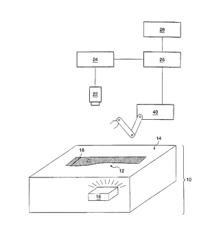
Figure 1 illustrates the basic design of the preferred embodiment of the presentinvention. A light table 10 is used to support and illuminate a workpiece 12. The surface of
the light table 10 is comprised of a light transmitting material 14 which supports the
10 workpiece 1'. The surface 14 will workbest if formed from a transparent material such as a
transparent plastic or glass plate, however, a translucent material can also be used. A light
source 16 is located beneath the surface 14 and shines light through the surface 14 and against
the underside of the workpiece 12. The light source 16 may take the form of anv well known
light source such as, but is not limited to, conventional light bulbs, fluorescent li~hts and
15 halogen lights. Light source 16 must provide light of sufficient intensity, given the
characteristics of the material used to construct the surface 14 and the fabric used to construct
fabric workpiece 12. to illuminate substantially the entire surface 14 and penetrate. at a
visually reduced intensity. a single ply of fabric making up the workpiece 12. In the
preferred embodiment, the intensity is such that the surface of the light table around the
20 workpiece 12 would have a first and brightest intensity. the portion of the workpiece ~vhich is
a single ply of fabric would be illuminated to a second, lower intensity. The difference
between the two intensities of light visually outlines the shape of the entire workpiece. Any
overlapped portions of the fabric workpiece such as a seam~ are visually detectible as a third
intensity of transmitted light which would be very low, wherein such areas appear ~isually as
25 a dark or black stripe on the workpiece. To increase the usefulness of the light table for use
with a wide variety of fabrics of varying thicknesses and translucency, it is desirable to
provide a variable intensity control for light source 16 so that light intensity can be adjusted
for maximum contrast between the light table lO, workpiece 12 and seam 18.
Although Figure I illustrates the light table as merely having a surface 14 and a light
30 source 16 beneath, it may have numerous different embodiments. For example. instead of the
table configuration in Figure 1. the light table may take the form of a box with a clear top to
support the workpiece 12 and a light source within for illumination.
- 4 -
CA 022~1400 1998-10-13
WO 97/49062 PCT/US97/10456
By using a light table 10 of sufficient size~ the entire workpiece 12 can be illllmin~ted
at the same time. This allows a complete image of the shape of workpiece 12 to be captured
instead of having a single point light which illllmin~tes only a small area of the workpiece 12
at a given time. A faster and more accurate rendition of the shape of the workpiece 12 is
5 thus generated. Furthermore, because the entire workpiece 12 is illllmin~t~d at the same time.
~ the workpiece does not have to be moved in relation to the light source 16 or vice versa but
can remain stationary as the image is captured.
The workpiece 12 may be any type of fabric which is at least somewhat transparent or
translucent and includes a wide variety of woven and non-woven fabrics ranging from fine
10 silk to heavy denim. By "at least somewhat transparent or translucent" is meant that the
fabric will transmit light at a somewhat reduced intensity. This means at least a portion of
the light from the illumination source 16 will pass through the fabric. This is in contrast with
non-translucent~ opaque fabrics such as vinyl~ leathers~ or rubber which block substantially alk
if not all, li_ht from passing through itself.
The intensity of the light passing through workpiece 12 will varv. however. depending
on the thickness of the fabric. As noted above, if the intensity of light source 16 is properly
selected or adjusted~ seam 18, which consists of overlapping fabric pieces, will block
substantially more light than a single layer of the same fabric and will appear visually as a
dark or black stripe. A seam 18 can be formed in many conventional ways. For example,
the seam 18 can be formed by overlapping and sewing together two fabric workpieces. or it
can be formed by the same workpiece being folded on itself as in a cuff.
A camera 22 is preferably located above the light table 10 for capturing an image of
the light table. including any workpiece 12 placed thereupon. Preferably. camera 2' is a
CCD vision system video camera. An image processor 24, coupled to the camera 22. filters
the image and converts the image to a digital signal. The processor 24 is preferably coupled
to a controller such as computer 26 which can process the image according to instructions
contained in a memory 28. Although shown here as two separate items. image processing
functions can be performed within the computer 26 thus elimin~ting the need for a separate
image processor 24.
~ 30 Computer 26 contains, in memory 28~ a stored image of the shape of workpiece 12
with a known seam orientation and a known workpiece orientation. The digital signal
captured by the camera 22 is processed to deterrnine the orientation of the workpiece 12 from
a combination of the workpiece shape and the location of at least one seam 18 in the
CA 022~1400 1998-10-13
W0 97/49062 PCT/US97/10456
workpiece 12. Location of the seam is accomplished by locating the area having the lowest
intensity of light passing through the workpiece 12. As indicated above. more light is able to
pass through a single laver of fabric 20 than through a seam. The processing means
distinguishes the differences in light intensity across the light table 10 to determine shape of
5 the workpiece 12 as placed on the li~ht table 10, and the location of the seams. As noted
above~ those areas which correspond to the seam 18 will appear as a substantially dark or
black line across the workpiece 12. After processing, the computer 26 can compare the shape
of the workpiece and the location of the seam or seams with a stored image of a sample
workpiece having a known and/or desired orientation and one or more "landmark" seams in
10 order to determine whether the orientation of the workpiece 12 on the light table 10 is as
desired or whether the workpiece 12 is not correctly oriented (e.g., rotated and/or inverted on
the light table). Thus, the present invention is particularly useful for reorienting fabric
workpieces which have two different sides (such as, for example, denim fabric which has a
dark side and light side) where the fabric workpieces have become inverted during processing,
15 and must be reoriented to produce a marketable garment in which all the sewn parts have the
desired side out.
Once the orientation of the workpiece 12 is determined. subsequent automatic
reorientation and manipulation of the workpiece 12 is possible and can be performed to
enable further operations on the workpiece 12. These operations include but are not limited
20 to. additional sewing, stacking or reorientation of workpieces in a known orientation, for
transfer to another work station, or other workpiece manipulations. Furthermore, because the
camera 22 is able to capture a complete picture of the workpiece and because the processing
unit/computer 26 is able to compare the captured image with a complete stored image, it does
not matter how the workpiece is placed on the table 10, as long as it lies flat. In other words.
25 the workpiece can be rotated in either direction~ or inverted, from its desired orientation on
the table and the processing unit/computer 26 can still determine its orientation.
As shown in Figures 1 and 2, co~ ulel 26 can also be in communication with and
control a manipulating device 30, such as, for example, an industrial robot or individual
hydraulicallv or pneumatically controlled arms~ for removing a workpiece from a stack of like
30 pieces or from a conveyor, for positioning the workpiece on the ilhlmin~ted surface of light
table 10, for reorienting the workpiece on the light table 10 to match the orientation of the
stored image. if that orientation is plefe..ed or desired. and for moving the workpiece off the
light table 10 after orientation has been determined and/or adjusted.
CA 022~1400 1998-10-13
- wO 97/4go62 PCTNS97/10456
Figure 2 illustrates an alternate preferred embodiment of the optical seam locator.
Here. all elements are the same as the similarly numbered elements of Figure 1 with the
addition of the conveyor track 30 and the drive assembly 32. The track 30 is positioned to
pass a plurality of workpieces 12 over the light table 10. This allows for automatic inspection
5 of numerous workpieces. The conveyor track 30 can be powered by a drive assembly 32 of
any well known type and should be transparent or translucent such that the light shining from
the light table 10 can pass through to the camera 22. This embodiment allows for the quick
determination of the orientation of numerous workpieces 12 in succession. Reorientation~ if
desired. can be accomplished through the use of a robot controlled by computer 2~.
10 Workpiece 12 is stationary when the camera 22 captures an image thereof.
Alternatively, a light source 34 could be used in conjunction with a transparent or
translucent conveyor instead of a light table~ as shown in Figure 3. Because the track 30 is
able to support the workpiece 12. and is translucent enough that light can pass through it. a
light table such as the one shown in Figure 2 would not be needed.
The invention has been described in terms of the preferred embodiment. One skilled
in the art will recognize that it would be possible to construct the elements of the present
invention from a variety of materials and to modify the placement of the components in a
variety of ways. While the preferred embodiments have been described in detail and shown
in the accompanying drawings, it will be evident that various further modifications are
20 possible without departing from the scope of the invention as set forth in the following
claims.