Note : Les descriptions sont présentées dans la langue officielle dans laquelle elles ont été soumises.
CA 022~1610 1998-10-08
W097/37804 PCT~S97/05939
SMA~L-SHANR TOOT~ FOR AUTOMATIC LAT~S
Field of the Invention
The present invention relates to cutting tools for
automatic lathes, and more particularly, to such cutting tools
having an interchangeable tool insert attached to a shank with
the insert defining a general~y rhomboidal shape and having a
cutting surface extending beyond the tip of the shank for
cutting a workpiece, and particularly suited for use with
small-shank cutting tools having shanks less than 9 mm in
width.
Backaround Information
In a typical Swiss-type automatic screw machine, a
plurality of cutting tools are radially disposed about a
sliding headstock for cutting a workpiece which is rotatably
and longitudinally driven relative to the tools. The cutting
tools are typically comprised of a tool bit or insert attached
to a tool holder or shank, and the shanks are selectively
actuated to move the tools radially into and out of engagement
with a workpiece to cut the workpiece as desired.
The tool shanks are typically made of rectangular-
shaped bars which are slidably mounted within corresponding
channels formed in a tool turret or gauge plate mounted around
or above the headstock. The tool shanks are provided in the
following industry-standard widths: 7 mm, 8 mm, 10 mm, 12 mm,
5/16 inch, and 1/2 inch. Most smaller automatic screw
machines can accommodate only the 7 and 8 mm width shanks
(referred to herein as ~small-shank" cutting tools), whereas
the larger automatic screw machines use the shanks having
widths of 10 mm or larger.
Cutting tools having a shank width of 8 mm or
larger are commercially available in several different
configurations. In one type, the carbide tool bits are brazed
to the ends of the shanks. In another type, interchangeable
carbide tool inserts are screwed or clamped to the ends of the
CA 022~1610 1998-10-08
W097/37804 PCT~S97/05939
shanks. One advantage of the brazed cutting tools, is that
they are relatively less expensive to manufacture and the tool
bits are strongly secured in place. One advantage of the
interchangeable tool inserts, on the other hand, is that the
inserts are provided with more than one cutting edge so that
when each edge becomes worn, chipped or otherwise requires
replacement, the tool insert may be relatively quickly rotated
or indexed on the shank by adjusting the fastener or clamp to
position a fresh cutting edge of the insert into a cutting
position. The clamping mechanisms may provide a secure lock;
however, they are relatively bulky and may not always be
easily mounted within the screw machines, particularly the
machines requiring small-shank tools, and may therefore
require additional set-up time and installation expense.
Currently, most cutting tool manufacturers provide
the same series of tool inserts for use with each of the
respective manufacturer's available shanks. In addition, most
manufacturers only provide interchangeable tool inserts for
tools having shank widths of 10 mm or larger. For cutting
tools having shank widths of less than 10 mm, these
manufacturers recommend the use of brazed tools, as described
above. One drawback of the brazed tools, however, is that
once the tool bits become worn, they must be ground to reform
the cutting edges, or the entire tools must be replaced, and
the machine must be reset to accept the re-ground tool. The
inventor of this application is not aware of any manufacturer
that has provided cutting tools with interchangeable inserts
for shank widths of less than 8 mm, and he is aware of only
one manufacturer that has provided cutting tools with
interchangeable inserts for shank widths of 8 mm.
Referring to FIG. 1, a typical such commercially-
available cutting tool is indicated generally by the reference
numeral 1. The cutting tool 1 includes a rectangular-shaped
shank 2 having a width of 8 mm, and a rhomboidal-shaped (or
diamond-shaped) insert 3 attached to one end of the shank by a
screw 4. As can be seen, the tool insert 3 is defined by an
CA 022~l6l0 l998-l0-08
W097/37804 PCT~S97/05939
inscribed circle which is approximately equal to the width of
the shank 2 (8 mm), and the shank defines a single tool-
supporting edge 5 for engaging and supporting a corresponding
edge of the tool insert. One of the problems encountered with
this configuration is that if the insert is torqued in the
clockwise direction in FIG. 1, the tool insert may become
relatively easily dislodged on the shank, thus rendering the
cutting tool ineffective and requiring time-consuming
breakdown and set-up to either repair or replace the tool.
As illustrated in broken lines in FIG. 1, industry
has attempted to overcome this problem by providing the shank
with another, smaller supporting edge 5' on the opposite side
of the tool insert relative to the first supporting edge 5.
However, because of the size and location of the second
supporting edge, it provides little additional support and has
proven to break away relatively easily, and has otherwise
failed to effectively prevent the insert from being dislodged
when torqued in the clockwise direction in FIG. 1.
Accordingly, the prior art has failed to provide an
acceptable small-shank cutting tool with interchangeable,
rhomboidal-shaped tool inserts, and it is an object of the
present invention to provide such a cutting tool which
overcomes the drawbacks and disadvantages of the above-
described prior art.
Summarv of the Invention
The present invention is directed to a small-shank
cutting tool for an automatic lathe, comprising a tool shank
defining a rectangular cross-sectional shape having a maximum
width of less than approximately 9 mm, and preferably either 7
mm or 8 mm, and including a tool recess defined at one end of
the shank by two tool-supporting surfaces oriented at an acute
angle relative to each other. One of the tool-supporting
surfaces is generally parallel to an adjacent side of the
shank, and the shank defines an elongated body portion
extending between the respective tool-supporting surface and
CA 022~l6l0 l998-l0-08
W097/37804 PCT~S97/05939
side of the shank having a thickness of at least approximately
1.0 mm for enhancing the structural integrity of the
respective tool-supporting surface. A rhomboidal-shaped tool
insert of the cutting tool is seated within the tool recess of
the shank with two sides of the insert each engaging a
respective tool-supporting surface, and a substantial portion
of the other two sides of the insert extending beyond the end
of the shank and forming a cutting tip for cutting a
workpiece. The rhomboidal-shaped insert defines an inscribed
circle having a diameter less than approximately g0% of the
maximum shank width, and a fastener aperture extending through
the approximate center of the inscribed circle defining a
diameter less than approximately 70% of the diameter of the
inscribed circle. A threaded fastener of the cutting tool
extends through the fastener aperture and is threadedly
attached to the tool shank for fixedly attaching the tool
insert to the tool shank. The threaded fastener defines a
counter-sunk head having a maximum diameter less than
approximately 70% of the diameter of the inscribed circle, in
order to maintain sufficient structural integrity of the
insert to avoid failure during machining operations.
One advantage of the present invention is that an
interchangeable, rhomboidal-shaped insert may be used with
either 7 mm or 8 mm width shanks, and the shank engages and
supports such inserts along a substantial portion of two sides
of the insert to fixedly secure the insert and prevent the
insert from being dislodged or rendered defective in a like
manner as encountered with the prior art small-shank cutting
tools described above.
Other objects and advantages of the present
invention will become apparent in view of the following
detailed description and accompanying drawings.
CA 022~l6l0 l998-l0-08
W097/37804 PCT~S97/05939
srief Descxi~tlon of the Drawinqs
FIG. 1 is a side plan view of a prior art cutting
tool having an 8 mm width shank and an interchangeable tool
insert.
FIG. 2 is a side plan view of a shank or tool
holder of a cutting tool embodying the present invention.
FIG. 3 is a top plan view of the shank of FIG. 2.
FIG. 4 is a side plan view of an interchangeable
tool insert embodying the present invention for attachment to
the shank of FIGS. 2 and 3.
FIG. 5 is an elevational view of a threaded
fastener embodying the present invention for attaching the
interchangeable insert of FIG. 4 to the shank of FIGS. 2 and
3.
FIG. 6 is a top plan view of the threaded fastener
of FIG. 5.
FIG. 7 is a partial-schematic, elevational view of
several different configurations of the cutting tool of the
present invention illustrating several exemplary types of
machining operations that may be performed with the different
configurations.
Detailed Descri~tion of a Preferred Embodiment
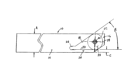
In FIGS. 2 and 3, a typical tool holder or shank
embodying the present invention is indicated generally by the
reference numeral 10. The shank 10 is adapted to hold one or
more interchangeable tool inserts, shown typically at 12 FIG.
4, for use in an automatic screw machine, and is particularly
suitable for use in ~small-shank~' screw machines that can only
accommodate shanks having widths of less than 9 mm.
Currently, the industry standard shank widths for such ~small-
shank~ machines are 7 mm and 8 mm.
CA 022~l6l0 l998-l0-08
W097/37804 PCT~S97/05939
As shown in FIG. 2, the shank 10 defines an
elongated or longitudinally-extending body 14 having a
rectangular cross-sectional configuration. In the embodiment
of the present invention illustrated, each of the four sides
of the body 14 define an equal width "A" forming a square
cross section. One end of the body 14 of the shank defines a
tool recess 16 for receiving and supporting a tool insert 12
(FIG . 4), as is described further below. The recess 16 is
defined by a first tool-supporting surface 18, a second tool-
supporting surface 20, and a base surface 22 extending between
the first and second surfaces and oriented normal to these
surfaces. As shown in FIG. 2, the first and second tool-
supporting surfaces 18 and 20 are oriented at an acute angle
~s~ relative to each other, and the outermost end of each
tool-supporting surface is oriented tangential to an inscribed
circle "IC" defined by each tool insert 12 (FIG. 4).
As can be seen in FIG. 2, the first and second
tool-supporting surfaces 18 and 20 are positioned on the body
14 so as to define an elongated lip or supporting body section
24 behind the second tool-supporting surface 20 and havlng a
thickness "C". In order to provide adequate support for the
tool insert when received in the recess 16 and to otherwise
ensure the structural integrity of the cutting tool, the
thickness C of the lip 24 is preferably at least approximately
1.0 mm for a shank having a width A of approximately 7 mm, and
may be thicker for larger-width shanks. As also shown in FIG.
2, the shank 10 defines a relief pocket 26 formed at the
innermost ends of the first and second tool-supporting
surfaces 18 and 20.
Turning to FIG. 4, the interchangeable tool insert
12 has four sides forming a substantially rhomboidal or
diamond shape, including two parallel first sides 28 and two
parallel second sides 30. Each first side 28 of the insert is
oriented at an acute angle B relative to a respective second
side 30, and the adjacent pairs of first and second sides each
form a respective cutting tip 32 having a depth "D", as shown
CA 022~l6l0 l998-l0-08
W097/37804 PCT~S97/05939
in FIG. 4. Each cutting tip 32 defines one or more respective
cutting edges which are shaped and configured in accordance
with the particular type of machining operation to be
performed, as is described further below. For example, as
shown in FIG. 4, a chamfer is formed at the juncture of each
respective pair of first and second surfaces 28 and 30,
respectively. The tool insert 12 is preferably made of
carbide steel, but may equally be made of other desired
materials.
The angle B of the tool insert shown in FIG. 4 is
the same as the angle B of the shank shown in FIG. 2 so that
when the insert is received within the recess 16 of the shank,
the respective first and second surfaces 28 and 30 are seated
in conforming engagement with the first and second tool-
supporting surfaces 18 and 20 of the shank, respectively, to
securely support the insert on two sides. In the embodiment
of the present invention illustrated, the angle s is
approximately 35-; however, as will be recognized by those
skilled in the pertinent art, this angle may changed as
desired depending upon the requirements of a particular
cutting tool design or other machining system. When the tool
insert 12 is received within the recess 16 of the shank,
preferably substantially the entire depth D of the respective
cutting tip 32 extends beyond the end surface 33 of the shank
(FIGS. 2 and 3), as is described further below.
As shown in broken lines in FIG. 4, the insert 12
defines an inscribed circle "IC", which is defined by the
diametrical distance between either the opposing first sides
28 or the opposing second sides 30 of the insert. In the
embodiment of the present invention illustrated, the tool
insert 12 iS designed for tool shanks having a width A of 7 mm
or greater, and therefore the diameter of the inscribed circle
IC is approximately 6 mm. Accordingly, in a shank 10 having a
width of 7 mm, the thickness C of the supporting lip 24 is
approximately 1 mm, and in larger-width shanks the thickness C
may be greater. In accordance with the present invention, for
CA 022~l6l0 l998-l0-08
W097/37804 PCT~S97tO5939
such small-width shanks (i.e., 8 mm or less), the diameter of
the inscribed circle IC should be no more than approximately
90% of the width A of the shank, and for 7 mm shanks, the
diameter of the inscribed circle IC is preferably
approximately 86% or less of the shank width, in order to
ensure that the lip 24 has sufficient thickness and structural
integrity to fixedly support the tool insert during machining
operations. Accordingly, the diameter of the inscribed circle
IC is preferably within the range of approximately 5.5 mm to
6.5 mm for shanks having a width within the range of
approximately 7 mm to 8 mm
As also shown in FIG. 4, the tool insert 12 defines
a counter-sunk aperture 34 extending through the approximate
center of the inscribed circle IC for receiving a threaded
fastener 36 (FIG. 5) to fixedly attach the insert to the
shank. The counter-sunk aperture 34 defines a maximum
diameter E which is sufficiently less than the diameter of the
inscribed circle IC of the insert to maintain its structural
integrity. As shown in FIG. 5, the threaded fastener 36 is
preferably a counter-sunk torque screw defining a maximum head
diameter E, which is approximately the same as the maximum
diameter E of the counter-sunk aperture 34 of the tool insert.
In this embodiment of the invention, wherein the tool insert
defines an inscribed circle IC having a diameter of
approximately 6 mm, the diameter E should be no more than
approximately 4 mm, and is preferably approximately 3.5 mm.
However, as will be recognized by those skilled in the
pertinent art, the diameter D may be changed as required
depending upon the inscribed circle of the insert. In
accordance with the present invention, for tool inserts having
an inscribed circle IC of approximately 6 mm or less, the
diameter E should be no more than approximately 70% of the
diameter of the inscribed circle. Similarly, for the insert
of the invention wherein the diameter of the inscribed circle
IC is within the range of approximately 5.5 mm to 6.5 mm for
shank widths within the range of approximately 7 mm to 8 mm,
the maximum head diameter E will be within the range of
CA 022~l6l0 l998-l0-08
W097/37804 PCT~S97/05939
approximately 3 mm to 4.5 mm depending upon the specific
minimum shank width and inscribed circle selected.
Also with reference to FIG. 5, in this embodiment
of the invention the angle F of the conical-shaped surface 38
of the fastener head is approximately 60' (the "counter-sink
angle"); however, as will be recognized by those skilled in
the pertinent art, this angle may be changed within limits
depending upon the requirements of a particular cutting tool
design or other machining system. In accordance with the
present invention, the angle F is preferably within the range
of approximately 52' to 68' to minimize the overall head
diameter. As will also be recognized by those skilled in the
pertinent art, the surface angle of the counter-sink aperture
34 is selected to substantially match the angle F of the
fastener 36 and is preferably configured so that when the
fastener is received within the aperture and threadedly
engaged with the shank, the top of the fastener is at
approximately the same level as the top edge of the aperture.
As shown in FIGS. 2 and 3, the shank 10 defines a
threaded bore 40 for threadedly receiving the fastener 36 upon
attachment of the tool insert 12 to the shank. The threads of
the fastener and bore are preferably relatively fine, and in
the preferred embodiment illustrated a "M2.5-4H" thread is
employed (2.5 mm pitch x 4 threads per mm). Accordingly, the
tool insert 12 is seated within the recess 16 of the shank
with a respective first side 28 of the insert engaging the
first tool-supporting surface 18, and the adjacent second side
30 of the insert engaging the second tool-supporting surface
20 of the shank. The fastener 36 is then inserted through the
counter-sunk aperture 34 of the insert and threadedly engaged
within the threaded bore 40 of the shank to fixedly secure the
insert to the shank.
As mentioned above, the cutting tip 32 of each
insert 12 may take any of several different shapes and/or
configurations, depending upon the type of machining operation
CA 022~l6l0 l998-l0-08
W097/37804 PCT~S97/05939
to be performed. For example, as shown typically in FIG. 7,
the cutting tip 30 of the insert 12 may be ground or otherwise
shaped in the several different configurations shown to
perform front turning, back turning, cut off, threading,
plunge and turning, and grooving operations. On the upper
side of the workpiece in FIG. 7, the three exemplary cutting
tools of the invention are shown in bottom plan view, whereas
on the lower side of the workpiece the three cutting tools are
shown in top plan view.
One advantage of the cutting tool of the present
invention is that because the diameter of the inscribed circle
IC is preferably less than approximately 6 mm, for small-width
shanks having a width of 8 mm or less, there is sufficient
space to one side of the tool insert when attached to the
shank to provide a second tool-supporting surface and lip for
engaging and supporting the rhomboidal insert on two sides.
Accordingly, the problems associated with the prior art small-
shank cutting tools with interchangeable inserts are
substantially avoided.
As will be recognized by those skilled in the
pertinent art, numerous changes and modifications may be made
to the above-described and other embodiments of the present
invention without departing from its scope as defined in the
appended claims. Accordingly, this detailed description of a
preferred embodiment is to be taken in an illustrative, as
opposed to a limiting sense.