Note : Les descriptions sont présentées dans la langue officielle dans laquelle elles ont été soumises.
CA 02251774 1998-10-14
SafetY Func~on Element for a I,ine
The inventioll concerns a safet~ fimc~on element to ir~uence or control fluid
mediums in a line, in particular a double-wa~led safiety line whose walls are
spaced at a distance to each other throu~ a hollow space, the element being
pro~ded with a housing ~ormed by walIs, the housing bei~g enclosed on a~l
sides by a second wall, which is spaced at a distance to the ~rst waII throug~
a hollow space and ~he hollow space is closed so as to be; ,as~ght
In pip~ng syste~s in many cases easily ;nfl~mm~ble or explosive li~quids as
well as gases ~nd products that endanger the ~ater an~ a~e in~urious to
he~lth and the e. . v, . ollment are t~ sported. Because an Imcontrolled releaseo~the ~nsported medium would result in significant damage a~d risks, for
~revenl~ve purposes, the use of double-w-~Ucd s~fcty l~nes is know~l, who~e
walls are spaced at a distance to each other th~ough a hollow space. ~uch
safety lines are disclos~d by U~PS 5,228,472 in which shuto~valves are
already inst~lled m the line. Irs th~s way not only is protection against an
escape of the medium direc~[y ~ pSo~ * is also possible to connect the
hollow space to a m~s~lnnS~ device to check its contents, for example, a
detection de~ice for specific g~s or a pressure gauge. Therefore a leak
report and subsequent
AM~NDEl~) SEIEE~
IPEA/E:P
CA 02251774 1998-10-14
--2--
cut~f~oftransportth~ough the line is effected as soon as the medium ellters
the hollow space so that the risk of a spillage affechng the e ..v"o~ ent is
completely ruled out.
~s a rule, lines are prov~ded with a m~ tude of filnct~on elements.
Examples are non-~eturn or shutoff valves, slide valves, pumps or flow
meters, which are connected respechvely~ ~ia flan~s, to ~e line pipes which
may Gomprise rigid or fle~ble matenal In the region of the filnct~on
elements no suitable measures are known to provide protection aaginst tlle
medium leaking. On the one hand, this h~ the consequerlce that
operahonally the function elements represent a considerable source o~
dan~er with le~kat,es occumng unth above average frequency compared
with the line On the other hand, during the coIlstruchorl of a line it means
significantly higher expe diture becallse perma~ent acGess must ~e
guaranteed, also by statute, even if the line is la~d uD~er~round, to the
function elernents. ThOEefore, in the state-of-t~e-ar~ the function element is
f~tted either in a shaft or an und~ uud loop so that significant ex ra costs
are the disadva~eous consequenGe. In addition to the fimchon elements
themselves, the fLanges, to which they are connected~ for example, by means
of bolts to fit tigk~y wi1~h the adjacent line, I ~plescnt fi~r~er re~ions in
which leaks occur especially ~equently
~a~nst ~is back~round~ it is the object of the invention to deYelop a safet~
... ... .. .... _ . ..
CA 02251774 1998-10-14
fimction element wbich offers easily controlled and iInproved protection
aga~nst leakage of the medium and therefore does not requ~re direct access.
In accordance with the inYention ~Is task Is solved there~n th~ t~e ~OUSL~g
is enclosed on all sides by a second wall~ which is spaced at a dis~ce to the
first walI ~rough a hollow space, whic~ is closed so as to be gas~ht and
connectable ~o a measu~n~ de~ice to check its contents and which is
connected ~ia one or more bores to a groove which Is disposed
circumferentia~ly to the line ~n the sealing surfàce of the :llange or its seal
The proposed safety functio~ element is e~closed by a hous~g which has
two walls~ preferably made ~om steel, on all sides w~ich are spaced at a
dis~nce to each other l~roug~ a hollow space The hollow space is closed so
as to be gasti~ht and is connectable or perlnanendy eoDnected to a
measurlng dev~ce to check its contents It is ~erefore possible to detect
leakage of the medium into the hollow space a~d to under~ake measures, in
par~cular to sw~tch of ~the line, before a leakage ~om the hollow space into
t~e environment occurs In order to ~lso be able to detect a pendi~g leak in
the region of the flallge, rts sea~ing sur~acc is provided wI[h a grooYe
cIrcumfereIltial to the li~e, which is, for example, rni~led The depth of the
~roo~e IS to be selected i~ such a way that the seal of the flange pe~e~ates at
most partially lherein so that across its ent~re length a continuous channel is
CA 02251774 1998-10-14
reta~ed. ~7ia olle or more bores, or a~l Lules produced in another way, ~ie
base ofthe groove is connected to the hollow space ofthe housing. If the
medium located in the ~ine penetrates into ~he se ling surfiace, t~at is, there is
an imminent nsk of a leak, it reaches ~he holIow spaGe via the groove and ~e
bores a~d can be detected there us~g the me~sllnn~ de~ce In this event~
safety measures can then also be taken
The adYautabe of ~he filnction element according to the invention consists in
sign~ficantly improved protechon a~a~nst leakage of ~he 1~ansported medium
~It~ouOh its use is also suitable for a conventiorlal single-wall line, the
installation ~n a double-w~lled safety line is preferred, Owing to ~e
improved protect~ve ef~eGt, it is no longer necessa~y to have direct access to
the eleme~t becau,se safety ~neasures can be ~keIl prior to a pending leak
and there is s~icient ~me for repairs Independent of the ~pe of
monitoring, the proposed solu~on allows ~e detec~on of even the smallest
Ieaks In particular, this creates co~siderable oost ad~antages because t~ere
is no need to create li~e Ioops above ~round or access sha~ts. ~urthermore,
outside envelopiDg or i~sula~ng layers do not impair the monitoring of the
filnction eleme~t,
The fun~tio-l element according to the invention presents itself part~cularly in
CA 02251774 1998-10-14
-5-
t~e case of shutoffde~ces, that is~ slide ~alves or valves whic~
compara~ely ~equen'dy l~ave to be installed i~ accessible regions.
Furthermore, the embod~ment aGcording to the invention is also
advantageous ~n the case of a non-retur~ valve which likew~se is ~equently
to be disposed inaccessibly On ~e o~er hand, many other fimchon
elements, ~or example, dirt ~aps, pumps or ilow meters, by way of contr~c
are generally arraDged so as to be easily accessible, for ~hlstance, in a
pump~ng station, so that direct monitoring is possible.
~unchon elements f~equently have an ~c~ve pa~t wbiGh engages with the
fluid medium~ for ex~mple, the disk o~ shutofFvalve. Usually a mechanical
coupler se~es as actuation which acts through a le~dthrou~,h ~n the ~ousing.
For ex~mple, a valve disk is moved by means of spindle as a coupler so that
it is adjustable via a handwheel or a motor t~at is attached to t~e housing To
prevent the medium fi~m leal~g along the l¢adthrough, in a developme~t of
the inve~ho~ it is proposed to connect ~e active part to the housing to fit
y ~ia a bellows inside of which the coupler engages e~dw~se. Tn this
way, the :lluid medium is div~ded by the leadtbrough, while the bellows does
not impair the mo~ement of ~le act~ve paIt owi~g to its deformabili~r.
Considerably ir~pro~ed protection agai~st leak~ge of the Inedium is the
ad~farltageous conseque~ce
CA 02251774 1998-10-14
~- ..
With the use of a bellows, it is practical if the volume between it a~ld the
ho~ls~ng ca~ be comlected to a measuring device to check its cor~tents so that
failure of ~e bellows.can also be detected.
The protec~on a~ainst a le~kaDoe of the medium can be filrther improved if
the coupler leadthrough is achieved by means of one or more bushes, so-
called safety bushes, which rest a~,a~nst the coupler so as to efEect a ~ght
seal In particular, in the case of a plurality of bushes, i~ this way a good
seal ca~ be achieved even w~thout a bellows.
For fill;n~ the hollow space between ~le hous~ng walls, it presents itselfto
~ use a compressed gas, e g. co,np~essed air, or a vacuum. As a consequence,
a leak call be detected simply through a change in the over~ ne~ e so
that a plam manometer is suf~iclent as the measuriDg device Basi~ally, it is
adva~tageous to be able to detect a leak in tbe interior wall facing the
medium as well as in the outer wall facing the en~ronment because in both
cases a sigDificaIltly higher risk of a leakage of the medium exists ~his
requLrement ;s fillfilled when compressed air or a ~acu~lm is ~n~oduced
because in both cases the pressure charlges. Howeve~, monitor -~g o~the
hollow space with a ~acuum ls not pemutted for combustible, explosi~e
substances and those that threaten the water Therefore, f~g tbe hollow
space w~th a protect~ve gas, for example, nit~oge~, is co~ceivable ~ a
CA 02251774 1998-10-14
--7--
protecti~e gas is Iocated ~n the hollow space, it is advantageous to have a
devioe that detec~; specificalIy the medium ~n the line to be able to detect
even the smallest of leaks
l~the fu~ctlon element according to the inYentioIl is flange-mounted to a
double-walled safety line, the hollow spaces of the safet~ line and housing
are connecte~ to one another. Ln addi~on, the groove is connected to the
hollow space of ~e safety lille vIa an aperture ~ the ila~ge part of the safety
line A seal in the flange is provided wi~ o~e or more apertures pa~a~lel to
the axis ofthe lille or consists oftwo co~centric parts so that the connection
between the ~,roove and aperture is not interrupted in the flarlge part ofthe
pipe.
continuous connection of the hoIIow spaces of pipe p~ts via a functio
element located between them has the advantage that signi~cant sections of
~e pipe can be monito~ed with one single measuring device If a leak is
detected, there is the problem o~the loc~li~tion ofthe d~m~ed place.
Therefore, in a fiurther development it is proposed ~t the bore bet~een the
flange and the hollow space can be closed by means of a locl~g device, for
example, a locking screw Thereby it is basica~ly imT1l~t~.n~1 whether the
bore between the hollow space of the safe~y line and the flaDge is concerned
or that of the housing and ~e flange. I~ bo~ cases the line ca~ be di~ided
sect~on-u ~se by closin o ~he lockin~ dev~ce so tha~ e search for the lealc is
CA 02251774 1998-10-14
',
-8-
made si~ific~y easler
Suitably the cross-sectional area ofthe housing ofthe safety fimction
element corresponds to the outer cross-section of the line in which it is used,
i e the shapes ofthe outer walls ofthe li~e a~d housing co~les~ d to each
other. In this way, spatia~ probIems are avoided during the in.~ ion o~the
sa~ety fil~chon element ~ecause there is no expansion of the cross-section
v~s~-~is the line. Small vanahons in the diameter are thereby conceivable, in
particular, a sl~ght expansion to filcilitate a suf~icient aperture cross-section
of the fimchon element to ~ lt excessive flow resistances. Cross-sec~onal
areas of the line and the housi~g which correspond to each other present
themselves iII pa~ular in the case of safety ~unction elements which do not
require ac~va~on from outside, for e~ample, a non-return value.
Further details, ~eatures and adYantages of thc invention can be taken ~om
the following des~ tive part in which with tlle aid of the draw~ng a typical
embo&e~t of ttle inverL~on is described in gTeater detail l'he drau~ng
shows in schematic representahon
Fig 1: cross-sect~on of a shutoff~valve according to the invenhon
CA 02251774 1998-10-14
F~g ~: cross-section of ~ non-reblrrl valve accord~ng to the inventiorL
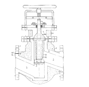
The valve in fig~lre 1 can be connected via two flanges (1) to pipes of a line
whose course thus continues along a chan~el (2) whose cross-section ca~ be
Glosed or changed w~th the dislc (3) of the valve. The actua~on of disk (3) Is
afl~ected by a sp~ndle (4) that travels out of the housing of ~e valYe alld is
movable v~a a handwheel which is attached to it endwise
To increase safety aga~st a lea~age o~'the meclium ~om chaDnel ~2), thevalve is surrounded by two walls (5, 6), which ellcl~se a hol~ow space (7).
Furthermore, hollow space (7) Is provided ~th a connection ~a which is
connectable t~ ~ measuring device, in particular a pressure gu~a,e, to check
its contellts If interior wall ~5) of the ~alYe is dama~,ed, the medium flowing
~n channel (2~ does not escape ir~to the env~ronment but ~Ilto hollow space
(7) The change of pressure arisi~g can be detected by the measunng device
fitted to cor~ect~on ~8) so th~t safety measures can be talcen and the valve
can ~e replaced ~efore a leakage occurs t~ough outer wall ~6). ~the hollow
space ~7) ls fi~led ~nth a medium ot~er than air or with a pressuse di~ering
~om t~e ex:terior ~r pressure, by means of ~e measun~lg device, leaks in
outer wa~ ) Gan also be detected
CA 02251774 1998-10-14
-1()-
The execution of mechanical actuating ele~ents, In the e~amp~e of sp~Ddle
(4), through the housing o~e valve, requires special protechon. The
exeGution is e~ected through a number of bushes (9), so ca~led safe~y
bushes, which rest aga~Dst spindle (4) so as to fit ~ghtly. l~he bottom end of
spindle ~4) is enclosed by a deformable bellows ~10) which is connected to
disk (3) a~ld ~nner wall (5) so as to fi~ htly. In this ~ay, the volume (11) of
a filr~er hol~ow spaGe is created between beL~ows (10) and ~nside wall (S),
with the consequence that the medium located in channel (2) does not reach
the leadtbrough c~f spilldIe (4). Volume (1 1 ) also can be monitored by me~ns
of bore ( 1~ a a measunrlg device to be able to deteGt a ~ilure of bushes
(9) or bellows (10).
To also gua~antee the monitoring of flarlges (1), ~ey are provided ~nside
with bores (13) which colmect groove (15) extending circumfere~al to its
sealing surface to hollow space (7). In ~he case of a faulty seal~ t~e esca~i,.gmedium reaches groove (15) and v~ bores (13) is di~ectecl into hollow space
(7) where it is detectable by the measuring device ~ia con~ec~on ~8)
Decisi~e is that groove ~15) is disposed more or less in the centre of sea~
surfàce (14) so ~at the leak is detected before the seal has been penetrated
in filll and befo~e leakage into the env~ro~ment Gan take place I~ this way,
good protection a~ st leaks is also given in ~e region of ~ange (1 )
CA 02251774 1998-10-14
Figure 2, shows a non-r~ valve according to ~e inYention where the
names of similar co~ cl-ts cor,respond to ~ose in figure 1. Disk (3) ofthe
valve is af~ ed to a }~les~ule spri~g (16) which is supported on inside wall
(5) o~the housing. I~ the liquid thus flows ~om top to bottom ~rough the
non-return valve, it is i~ an opened condit~on wbile pressure sprillg (16), in
case o~ the reverse direction of ~ow, presses disk (3) ~in~t its seat ( 17)
aIld thus closes the vaI~e. I~e monitoring of hollow space (7) is effected in
the case of this embodiment of the in~rention, for ex~nple, ~a connec~on
(8), which is located ~n a component which is flall~,e-mounted to fl~ge (I)
arld is comlected to hollow space ~7) via bores ~13). Groove (l~), which runs
circumferen~ally around sealing surface ( 14) is disposed i~ lts seali~g (18).
' As a result one obtains an easy-t~monitor safety fùnc~on element which
improves prote~tio~ a~ainst a leakage of mediums considerably and
substantially sirnplifies the layirl~ of such a li~e because the requirements inrespect of ~ ihilily of the e1ernent are reduced. The ~ v~.nent in
safety in all ~ndus~al secto~ in particular in the chemical industry, has
entered a stage w~th t~e in~en~on which allows damage to the env~ronrnent
to be avoided with rel~abie Gertainty