Sélection de la langue

Search

Sommaire du brevet 2253522 

Énoncé de désistement de responsabilité concernant l'information provenant de tiers

Une partie des informations de ce site Web a été fournie par des sources externes. Le gouvernement du Canada n'assume aucune responsabilité concernant la précision, l'actualité ou la fiabilité des informations fournies par les sources externes. Les utilisateurs qui désirent employer cette information devraient consulter directement la source des informations. Le contenu fourni par les sources externes n'est pas assujetti aux exigences sur les langues officielles, la protection des renseignements personnels et l'accessibilité.

Disponibilité de l'Abrégé et des Revendications

L'apparition de différences dans le texte et l'image des Revendications et de l'Abrégé dépend du moment auquel le document est publié. Les textes des Revendications et de l'Abrégé sont affichés :

  • lorsque la demande peut être examinée par le public;
  • lorsque le brevet est émis (délivrance).
(12) Demande de brevet: (11) CA 2253522
(54) Titre français: LECTEUR OPTIQUE - LENTILLE - CADRE
(54) Titre anglais: SCANNER-LENS-FRAME
Statut: Réputée abandonnée et au-delà du délai pour le rétablissement - en attente de la réponse à l’avis de communication rejetée
Données bibliographiques
Abrégés

Abrégé anglais


An accessory for flat bed scanners and photocopiers is provided. The accessory
allows pages from bound books, especially in the binding region to be scanned
or copied.
The accessory may comprise either a frame together with a lens, or a lens
alone. The
frame may be of varying geometrical shapes with a lens within the frame, and
with the lens
having one straight edge that may or may not be framed by a narrow frame or an
angled
frame. The frame and lens, or the lens alone sit on the top of the scanning or
photocopying
surface of the scanner or photocopier. In use, the spine of the book is placed
so that it
coincides with the unframed edge of the lens.

Revendications

Note : Les revendications sont présentées dans la langue officielle dans laquelle elles ont été soumises.


Page 6
CLAIMS
1. An attachment or accessory to flat bed scanners and photocopiers
comprising a rectangular frame housing a lens, whereby the frame borders
three sides of the lens with one side of the lens being free of a frame.
2. An attachment or accessory to flat bed scanners and photocopiers
comprising a rectangular frame housing a lens, whereby the frame borders
four sides of the lens with one side of the lens having a narrow frame.
3. An attachment or accessory to flat bed scanners and photocopiers
comprising a rectangular frame housing a lens, whereby the frame borders
four sides of the lens with the frame on the fourth side of the lens being
angled.
4. An attachment or accessory to flat bed scanners and photocopiers
comprising a frame of varying shapes housing a lens, whereby the frame
borders all sides of the lens, with one side of the lens having either a
straight
narrow frame or a straight angled frame.
5. An attachment or accessory to flat bed scanners and photocopiers
comprising a frame of varying shapes housing a lens, whereby the frame
borders all but one side of the lens, with the side of the lens not bordered
by
a frame, having a straight edge.
6. An attachment or accessory to flat bed scanners and photocopiers,
comprising a frame and lens, as defined in claims 1, 2 3, 4 and 5 in which
the frame is made of wood, metal, plastic, composite material or a composite
of materials.
7. An attachment or accessory to flat bed scanners and photocopiers,
comprising a frame and lens, as defined in claims 1, 2, 3, 4 and 5 in which
the dimensions, and shape of the frame will vary and change to
accommodate different models or makes of flat bed scanners and
photocopiers.
8. An attachment or accessory to flat bed scanners and photocopiers,
comprising a frame and lens, as defined in claims 1, 2, 3, 4 and 5, in which
the frame provides attachment points to affix the attachment or accessory to
flat bed scanner and photocopiers, as defined in claims 1, 2 3, 4 and 5 to the
flat bed scanner or photocopier and to reaffix the flat bed scanner or
photocopier's cover to the frame.

Page 7
9. An attachment or accessory to flat bed scanners and photocopiers,
comprising a frame and lens, as defined in claims 1, 2, 3, 4 and 5 in which
the frame provides no attachment points to affix either the attachment or
accessory to flat bed scanner and photocopiers, as defined in claims 1, 2, 3,
4 and 5 to the flat bed scanner or photocopier; or to reaffix the flat bed
scanner or photocopier's cover to the frame.
10. An attachment or accessory to flat bed scanners and photocopiers
comprising a lens of varying geometrical shapes with attachment devices that
enable the lens to be fixed to the surface of a flat bed scanner or
photocopier,
and the cover of the flat bed scanner or photocopier to be re-affixed to the
lens.
11. An attachment or accessory to flat bed scanners and photocopiers
comprising a frame and lens, or a lens with attachment devices as defined in
claims 1, 2, 3, 4, 5 and 10 in which the lens may be solid, hollow or a
lamination of materials.
12. An attachment or accessory to flat bed scanners and photocopiers
comprising a frame and lens, or a lens with attachment devices as defined in
claims 1, 2, 3, 4, 5 and 10 in which the surfaces of the lens may be of a
varied or differing grain or texture.
13. An attachment or accessory to flat bed scanners and photocopiers
comprising a frame and lens, or a lens with attachment devices as defined in
claims 1, 2, 3, 4, 5 and 10 in which the lens may be made out of plastic,
treated plastic, glass, or a composite of materials.
14. An attachment or accessory to flat bed scanners and photocopiers
comprising a frame and lens, or lens with attachment devices as defined in
claims 1, 2, 3, 4, 5 and 10 in which the lens may be so constructed as to fit
the entire window of the flat bed scanner or photocopier or any portion of the
window of the scanner or photocopier.
15. An attachment or accessory to flat bed scanners and photocopiers
comprising a frame and lens, or a lens with attachment devices as defined in
claims 1, 2, 3, 4, 5 and 10 in which the lens may be optically clear or
tinted.
16. An attachment or accessory to flat bed scanners and photocopiers
comprising a frame and lens, or a lens with attachment devices as defined in
claims 1, 2, 3, 4, 5 and 10 in which the lens may be tailored to pass only
certain spectrums of light or may admit polychromatic light frequencies.

17. An attachment or accessory to flat bed scanners and photocopiers
comprising a frame and lens, or a lens with attachment devices as defined in
claims 1, 2, 3, 4, 5 and 10 in which the lens may be polarized or non
polarized.
18. An attachment or accessory to flat bed scanners and photocopiers
comprising a frame and lens, or a lens with attachment devices as defined in
claims 1, 2, 3, 4, 5 and 10 in which the lens may be of varied density and
thickness.
19. An attachment or accessory to flat bed scanners and photocopiers
comprising a frame and lens, or a lens with attachment devices as defined in
claims 1, 2, 3, 4, 5 and 10 in which the lens has varying focal points.
20. An attachment or accessory to flat bed scanners and photocopiers
comprising a frame and lens, or a lens with attachment devices as defined in
claims 1, 2, 3, 4, 5 and 10 in which the lens gives rise to varying focal
lengths.

Description

Note : Les descriptions sont présentées dans la langue officielle dans laquelle elles ont été soumises.

CA 02253522 1998-11-09
Page 1
1 BACKGROUND OF THE INVENTION
The present invention generally relates to improvements in the scanning and
photocopying of bound documents in portrait mode.
The current design of flat bed scanners and photocopiers makes it difficult to
scan or
photocopy bound documents in portrait mode. Currently, when a person desires
to
scan or photocopy bound documents such as text books, in portrait mode, a
heavy
downward pressure is required to force the pages of the bound materials onto
the
scanner or photocopier window. This downward pressure is needed so that the
print
that is close to the binding region of the material, can be brought within the
optical
field of view of the scanner or photocopier. This increases the wear and tear
of
scanners and photocopiers and decreases the life span of the scanners or
photocopiers. The heavy downward pressure that is exerted on bound materials,
increases the stress on such materials, and decreases the longevity of such
materials.
The present invention is a frame and lens attachmentlaccessory to flat bed
scanners
and photocopiers, or a lens only attachment/accessory to flat bed scanners and
photocopiers. The present invention eliminates the need to place the heavy
downward pressure, on bound materials, that is required to force the bound
materials onto the scanner or photocopier window.
The frame is an optional component of the present invention. The frame, where
used, may have attachment points that enable it to be fixed to the top of the
scanner
or copier. Where there is no frame and only a lens is used, the lens may have
attachment devices that will enable it to be fixed firmly to the top of a flat
bed
scanner or photocopier.
The present invention will make it possible for a user to use a relatively
inexpensive
scanner or photocopier to easily scan small and large bound materials into the
binding region of the bound materials. The materials that are scanned may be
transparent or reflective. As well, the present invention will make it
possible to scan
or photocopy single sheet or spooled materials.
The present invention also makes possible a quick repositioning of the bound
material without the need to reposition the scanner or photocopier's field of
recognition. Because the present invention is an attachment to existing
scanners
and photocopiers, as opposed to a modification of scanners and photocopiers,
it can
35. be moved from scanner to scanner, from scanner to photocopier and from
photocopier to photocopier as appropriate. The attachment nature of the
present
invention also means that it can still be used when the owner of the scanner
or
photocopier upgrades to another scanner or photocopier.

CA 02253522 1998-11-09
Page 2
SUMMARY OF INVENTION
40 It is a principal object of the present invention to provide an attachment
or accessory
for flat bed scanners and photocopiers that permits the scanning and
photocopying
of bound materials in portrait mode without the need to exert a heavy downward
pressure to force the bound material to be scanned or photocopied onto the
window
of the scanner or photocopier.
45 Still another object of the invention is to provide an attachment or
accessory for flat
bed scanners and photocopiers that permits the easy scanning or photocopying
of
bound printed materials into the binding region of the printed material
A further object of the present invention is to permit bound material to be
easily
positioned parallel to the scan window of flat bed scanners and photocopiers.
50 The above and other objects of the present invention will become apparent
from a
reading of the following description taken in conjunction with the
accompanying
drawings which illustrate the preferred embodiments thereof.
BRIEF DESCRIPTION OF THE DRAWINGS
The present invention is illustrated by the attached drawings.
55. Figure 1: is a drawing of the optional frame component of the
present invention that houses the lens of the present invention. The
frame is shown with attachment points, shown as circles on left side of
the frame. The attachment points enable the frame to be attached to a
flat bed scanner or photocopier, and also enable the cover of a
scanner or photocopier to be affixed to the frame.
61. Figure 2: is a two dimensional drawing of the structure of the
present invention. The frame as shown in Figure 1, is shown in this
illustration as housing a lens. The whole invention is shown as fixed to
a scanner or photocopier by means of the attachment points. In this
illustration, the frame is shown with its end or edge extending beyond
the lens, and not enclosing the lens. The top edges of the parts of the
frame that do not enclose the lens are the Locating points B, one of
which is labeled in Figure 4.
68 Instead of being enclosed or housed in a frame, as shown in this
illustration, the lens may stand alone, but may have a variety of

CA 02253522 1998-11-09
Page 3
attachment devices that enable it to be fixed to the top of the flat bed
scanner or photocopier without the need for the frame.
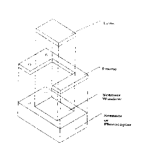
72. Figure 3: is a three dimensional view of the structure of the
present invention, when it is placed on top of a scanner or
photocopier. The illustration shows the separate components of the
present invention.
76. Figure 4: is a drawing of the present invention showing the
location points when a book is placed on the present invention.
Locating point A, is the top edge or side of the lens that comes into
contact with the meeting point, in the binding region of a book or other
bound material, between adjacent pages. Locating point A allows the
binding region of the bound material to come into the optical field of
view, or scan region of the scanner or photocopier. In this illustration,
Locating point B is the top end of one of the parts of the frame that
extends beyond the edge of the lens and does not enclose any part of
the lens. Locating point B makes possible the accurate positioning
and repositioning of the printed material within the scanner or
photocopier's optical field of view. Locating point B also prevents the
bound material from slipping to either the left or the right of the
scanner of photocopier. In this illustration, the invention itself is shown
resting on a flat bed scanner or photocopier.
DESCRIPTION OF THE PREFERRED EMBODIMENTS
92. Referring to the drawings, specifically Figures 1 to 4, which illustrate
the
present invention:
94. Figure 1 is a drawing of the frame that houses the lens of the present
invention. The purpose of the frame is to provide attachment points by means
of which the present invention may be fixed to the surface of the scanner or
photocopier.
99. In the illustration, the frame is shown with attachment points, shown as
circles on one of the sides of the frame. The attachment points enable the
frame to be attached to a flat bed scanner or photocopier, and also enable
the cover of a scanner or photocopier to be affixed to the frame. The frame is
optional.
104 Instead of a frame as shown in this illustration, the lens may be held in
position on the surface of the scanner or photocopier by a variety of
attachment devices. Where a frame is employed, the dimensions of the frame

CA 02253522 1998-11-09
Page 4
and its shape will vary and change to accommodate different models or
makes of scanners and photocopiers. The frame may be made of wood,
metal plastic, composite material or a composite of materials.
106 In this illustration, the frame is shown as being rectangular in shape,
with only three sides of the rectangle having a frame. One side is free of a
frame. The frame that houses the lens may also have four sides with a
narrow fourth side. The frame may also have three straight sides, and a
fourth angled side or edge.
111. The frame may also be of other varying geometrical shapes to
accommodate the shapes of the surtaces of various makes and models of
scanner and photocopiers. If a frame is employed, whatever its shape, one
side will be free of a frame, will have an angled frame, or will have a narrow
frame.
116 Figure 2 and Figure 3 are, respectively, a two and three dimensional
illustration of the present invention as it fits atop a flat bed scanner or
photocopier. Figures 2 and 3 show the frame, together with the lens, placed
atop a flat bed scanner or photocopier or fixed to the flat bed scanner or
photocopier by way of the attachment points.
121 The lens may be made of plastic, treated plastic, glass, or a composite
of materials. The lens may be solid, hollow or a lamination of materials. The
lens may be so constructed so as to fit the entire window of the scanner or
photocopier or any portion of the window of the scanner or photocopier. The
surfaces of the lens may be of a varied or differing grain or texture. The
lens
may be of varied density or thickness and may be of different shapes. The
lens may have positioning devices attached to it to accommodate various
media. The lens may also be optically clear or tinted. The lens may also be
tailored to pass only certain spectrums of light or may admit polychromatic
light frequencies. The lens may be polarized or non polarized.
Instead of being housed in a frame, the lens may have attachment devices
that enable it to be fixed firmly to the surface of the flat bed scanner or
photocopier.
134 Figure 4 is a drawing of the present invention showing the location
points of a bound material or text book, when it is placed on the present
invention. The invention itself is shown resting on a flat bed scanner or
photocopier. The frame of the present invention provides attachment points
to affix it to the flat bed scanner or photocopier and to reaffix the scanner
or
photocopier's cover to the frame. The top edges of the lens provides locating
points to allow the binding region of the bound printed material to be brought
into the optical field of view (the scan or copy region) of the scanner or
photocopier.
143 In this illustration, Locating point A, is the top edge or side of the
lens
that comes into contact with the meeting point, in the binding region of a
book
or other bound material, between adjacent pages. Locating point A allows the

CA 02253522 1998-11-09
Page 5
binding region of the bound material to come into the optical field of view,
or
scan region of the scanner or photocopier. In this illustration, Locating
point B
is the top edge of one of the ends of the frame that extends beyond the end
of the lens and does not enclose any part of the lens. Locating point B makes
possible the accurate positioning and repositioning of the printed material in
the scanner or photocopier's optical field of view. Locating point B also
prevents the bound material from slipping off to either the left or the right
of
the scanner of photocopier.
154 In use, in order to scan or photocopy bound material, the present
invention, with or without the frame, is fixed to the surface or window of the
scanner or photocopier. The bound material to be scanned or photocopied is
then placed on the surface of the present invention so that the page to be
copied is parallel to the scanner or photocopier window. The binding region
of the material is thus brought into contact with the top edge of the lens,
the
Locating point A. Where the optional frame component is used, the
remainder of the book or bound material is lodged between the two ends of
the frame that extend beyond the lens, Locating points B. Because the
binding region of the book comes into the optical field of view of the lens,
no
downward pressure is required to scan or photocopy the page concerned in
portrait mode. When one page is copied, the bound material may be quickly
and accurately repositioned so that the next page to be scanned or copied is
parallel to the scanner of photocopier's window. The cover of the scanner or
photocopier may be attached to the frame by the attachment points.

Dessin représentatif
Une figure unique qui représente un dessin illustrant l'invention.
États administratifs

2024-08-01 : Dans le cadre de la transition vers les Brevets de nouvelle génération (BNG), la base de données sur les brevets canadiens (BDBC) contient désormais un Historique d'événement plus détaillé, qui reproduit le Journal des événements de notre nouvelle solution interne.

Veuillez noter que les événements débutant par « Inactive : » se réfèrent à des événements qui ne sont plus utilisés dans notre nouvelle solution interne.

Pour une meilleure compréhension de l'état de la demande ou brevet qui figure sur cette page, la rubrique Mise en garde , et les descriptions de Brevet , Historique d'événement , Taxes périodiques et Historique des paiements devraient être consultées.

Historique d'événement

Description Date
Inactive : CIB de MCD 2006-03-12
Demande non rétablie avant l'échéance 2002-08-12
Inactive : Morte - Aucune rép. dem. par.30(2) Règles 2002-08-12
Réputée abandonnée - omission de répondre à un avis sur les taxes pour le maintien en état 2001-11-09
Inactive : Abandon. - Aucune rép dem par.30(2) Règles 2001-08-13
Inactive : Dem. de l'examinateur par.30(2) Règles 2001-04-12
Demande publiée (accessible au public) 2000-05-09
Inactive : Page couverture publiée 2000-05-08
Inactive : CIB attribuée 1999-01-15
Inactive : CIB en 1re position 1999-01-15
Symbole de classement modifié 1999-01-14
Inactive : CIB attribuée 1999-01-14
Inactive : Certificat de dépôt - RE (Anglais) 1998-12-21
Exigences de dépôt - jugé conforme 1998-12-21
Demande reçue - nationale ordinaire 1998-12-21
Exigences pour une requête d'examen - jugée conforme 1998-11-09
Toutes les exigences pour l'examen - jugée conforme 1998-11-09

Historique d'abandonnement

Date d'abandonnement Raison Date de rétablissement
2001-11-09

Taxes périodiques

Le dernier paiement a été reçu le 2000-11-07

Avis : Si le paiement en totalité n'a pas été reçu au plus tard à la date indiquée, une taxe supplémentaire peut être imposée, soit une des taxes suivantes :

  • taxe de rétablissement ;
  • taxe pour paiement en souffrance ; ou
  • taxe additionnelle pour le renversement d'une péremption réputée.

Veuillez vous référer à la page web des taxes sur les brevets de l'OPIC pour voir tous les montants actuels des taxes.

Historique des taxes

Type de taxes Anniversaire Échéance Date payée
Requête d'examen - petite 1998-11-09
Taxe pour le dépôt - petite 1998-11-09
TM (demande, 2e anniv.) - petite 02 2000-11-09 2000-11-07
Titulaires au dossier

Les titulaires actuels et antérieures au dossier sont affichés en ordre alphabétique.

Titulaires actuels au dossier
MILES ANTHONY HYMAN
Titulaires antérieures au dossier
S.O.
Les propriétaires antérieurs qui ne figurent pas dans la liste des « Propriétaires au dossier » apparaîtront dans d'autres documents au dossier.
Documents

Pour visionner les fichiers sélectionnés, entrer le code reCAPTCHA :


Pour visualiser une image, cliquer sur un lien dans la colonne description du document. Pour télécharger l'image (les images), cliquer l'une ou plusieurs cases à cocher dans la première colonne et ensuite cliquer sur le bouton "Télécharger sélection en format PDF (archive Zip)" ou le bouton "Télécharger sélection (en un fichier PDF fusionné)".

Liste des documents de brevet publiés et non publiés sur la BDBC .

Si vous avez des difficultés à accéder au contenu, veuillez communiquer avec le Centre de services à la clientèle au 1-866-997-1936, ou envoyer un courriel au Centre de service à la clientèle de l'OPIC.


Description du
Document 
Date
(aaaa-mm-jj) 
Nombre de pages   Taille de l'image (Ko) 
Page couverture 2000-05-03 1 31
Abrégé 1998-11-09 1 19
Description 1998-11-09 5 290
Dessins 1998-11-09 4 36
Revendications 1998-11-09 3 137
Dessin représentatif 2000-05-03 1 7
Certificat de dépôt (anglais) 1998-12-21 1 163
Rappel de taxe de maintien due 2000-07-11 1 109
Courtoisie - Lettre d'abandon (taxe de maintien en état) 2001-12-10 1 183
Courtoisie - Lettre d'abandon (R30(2)) 2001-10-22 1 171
Taxes 2000-11-07 1 46