Note : Les descriptions sont présentées dans la langue officielle dans laquelle elles ont été soumises.
CA 02255785 1998-11-23
Direct-Drive Coiler
The invention relates to a directly driven coiler for winding
rolled strip into coils in accordance with the preamble of claim 1.
Such directly driven coilers have become known, for example,
through DE-PS 17 52 185 or DE-OS 39 39 119. In these coilers, the
relative axial displacement between the coiler shaft and the
plunger connected to the segments is effected through mechanical
adjustment drives. These adjustment drives are bent lever drives
or spring assemblies and spacer elements which can only be actuated
when the coiler stands still. Any retightening during the coiling
process is not possible in these adjustment drives.
Piston-cylinder units have become known through DE-OS 35 02
452 by means of which it is possible to tighten and release the
spring assemblies which serve as adjustment drives and have the
above-described disadvantages.
EP-PS 0 004 854 also discloses a piston-cylinder unit which
serves directly as an adjustment drive for spreading and
despreading the coiler. However, these two coilers provided with
piston/cylinder units are not directly driven coilers of the
1
CA 02255785 1998-11-23
generic type mentioned above, but indirectly driven toilers in
which the drive motor is arranged next to the toiler shaft.
The toiler according to EP-OS 0 004 854 does have central
rotary feeds, so that, for example, retightening during the coiling
procedure is possible, however, if the drive motor for the toiler
were to be flanged directly to the toiler shaft, this would result
in difficulties in connection with the pressure medium supply
because, as a rule, only solid motor shafts are being used, so that
the pressure medium could not be conducted to the piston/cylinder
unit from the end of the shaft where the pressure medium is fed in.
However, if the pressure medium supply is to be placed through the
motor shaft, the magnetic effect in the motor could magnetize metal
particles in the pressure medium and could possibly lead to
clogging of the supply lines. In addition, complicated flexible
pressure medium connections would have to be provided in order to
bridge any lateral offsets or axial displacements between the drive
unit and the toiler shaft.
Rotary feeds have become known through DE-PS 38 06 931 through
which the pressure medium can be conveyed radially into a shaft;
these rotary feeds have very narrow manufacturing tolerances for an
optimum operation, wherein these very narrow manufacturing
tolerances exclude a use in difficult conditions as they prevail in
2
Ii I
CA 02255785 2003-12-03
rolling mills. In addition, these rotary feeds can only be
used up to structural sizes with a maximum 18 mm diameter at
the annular gap. Also for this reason, a use in rolling mill
plants, for example, rolling mill toilers, where
significantly greater diameters are used, could not take
place.
Therefore, the invention is based on the object of
further developing a directly driven toiler of the generic
type in such a way that it can be moved for spreading and
despreading even during the coiling operation.
Accordingly, in one aspect, the present invention
resides in direct-drive toiler for winding and/or unwinding
rolled strip with a drum composed of several segments which
can be moved so as to be spread and which rest with
sonically-shaped sliding surfaces against a coiling shaft
mounted rotatably cantilevered in a toiler housing, with a
plunger guided in the toiler shaft, wherein the plunger is
connected through a connecting flange to the drum segments,
wherein an axially extending cylinder (17) is mounted in the
toiler shaft (4), wherein the cylinder (17) has a piston
(16) which is connected to the plunger (12) and can effect a
relative axial displacement between the toiler shaft and the
plunger connected to the segments for producing a spreading
movement of the segments, wherein the toiler shaft (4)
extends beyond the cylinder (17) with a connected shaft
3
a ~ ,
CA 02255785 2003-12-03
extension (5) which closes the cylinder (17) in the
direction toward the axially arranged, directly driving
motor (7), and a rotary feed (8) is provided through which
pressure medium can be supplied to the piston/cylinder unit
(14) provided in the coiler shaft (4), characterized in that
the rotary feed (8) includes a housing (23) surrounding the
coiler shaft (4) and/or the shaft extension (5), wherein at
least one connection (27, 28) each is provided in the
housing (23) as a supply line and a discharge line and a
bushing (24, 25) is mounted in the housing (23) for each
supply line and discharge line, wherein the inner and outer
walls of each bushing are equipped with annular ducts (29,
31) which are connected to each other through at least one
essentially radially directed bore (30), wherein the outer
annular ducts (29) extend under the supply and discharge
connections (27, 28) of the housing (23) and discharge bores
(32) provided for the coiler shaft (4) and/or the shaft
extension (5) extend under the annular ducts (31).
The rotary feed provides a connection between the
piston/cylinder unit and a pressure medium force through
which the piston/cylinder unit can be supplied continuously
with pressure medium even when the coiler is driven so as to
rotate for the purposes of winding or unwinding strip.
In a more preferred aspect, the outer surface of the
sleeve (26) and/or the inner surfaces of the bushings (24,
25) are coated with ceramic material.
3a
CA 02255785 2003-12-03
The rotary feed is to be arranged in such a way that
none of the pressure medium lines extends through the shaft
of the motor flanged to the coiler shaft or the shaft
extension. Accordingly, it is provided to arrange the rotary
feed on the shaft extension. However, it is also possible to
provide the rotary feed on the coiler shaft itself.
3b
CA 02255785 1998-11-23
By using a double-acting step piston, the necessary spreading and
despreading forces can be predetermined in accordance with the
corresponding pressure of the pressure medium.
Since the rotary feed includes a stationary housing, the
external connections to the rotary feed can be arranged so as to be
stationary. Flexible hoses which are complicated and susceptible
to trouble are not necessary for these connections. The bushings
arranged within the housing can be manufactured significantly more
easily than if the housing would have the corresponding bushing
shape. In addition, by separately providing a housing, the
bushings and the sleeve can be realized with different material
pairings which ensure that the wear is as little as possible and
that they are adapted to each other with respect to their thermal
expansion in such a way that the gaps between the bushings and the
sleeves have optimum dimensions even in the difficult conditions of
rolling mills.
The sleeve equipped with the supply ducts can be very easily
manufactured. The use of this sleeve makes possible the use of
solid shaft extensions which do not have bores, so that a high
stability of the shaft extensions is ensured.
4
CA 02255785 1998-11-23
The pressure medium emerging between the sleeve and the
bushings, through which the bushing rests on an oil film on the
sleeve, is discharged through leakage oil lines to a tank. The
piston/cylinder unit is also provided with leakage oil lines which
end in the oil tank. The leakage oil lines of the piston/cylinder
unit only conducts oil if seals of the piston/cylinder unit are
detected. In that case, leakage oil indicators can be provided
which indicate the defect of the seals.
In order to ensure that the oil between the sleeve and the
bushings is not interrupted during the coiling operation, a
predetermined oil pressure level must always be maintained on the
pressure medium lines. The pressure medium line "spreading" is
then under sufficient pressure, so that a stable oil film is
ensured. The pressure medium line "despreading" could
theoretically be without pressure during the coiling operation,
which, however, would lead to damage of the rotary feed if the oil
pressure level were not also maintained on the pressure medium line
"despreading".
However, it is also possible to provide additional annular
ducts and radial bores in the bushings in order to maintain through
CA 02255785 2003-12-03
the ducts and bores statically an oil film between the
sleeve and the corresponding bushing. In that case, the
pressure medium lines "despreading" could also remain
without pressure during the operation. The oil film has the
purpose of absorbing the great weight of the bushings and
any acceleration forces which occur at the rolling mill
toilers as a consequence of vibrations. A significant
advantage of the static oil film results from the elastic
expansion of the sealing gap. As a result, defects with
respect to shape, for example, deviations from the circular
shape, which could occur as a result of the mechanical
processing and a change of the natural stress condition
under pressure and temperature, are compensated.
The ceramic coatings ensure a longer service life of the
sleeve and of the bushings. The resilient support of the
bushings in the housing, for example, through 0-rings, is
advantageous for compensating for symmetric deviations which
may occur when manufacturing the individual structural
components. The bushings are centered through the oil film
on the sleeve and are provided by the 0-rings with the
possibility of adjusting themselves to the position of the
sleeves.
The invention will be explained in more detail with the
aid of a drawing. In the drawing:
6
CA 02255785 1998-11-23
Fig. 1 shows a toiler according to the invention;
Fig. 2 is a partial sectional view corresponding to Fig. 1;
Fig. 3 shows a piston/cylinder unit according to the
invention;
Fig. 4 shows a rotary feed according to the invention.
Fig. 1 shows a toiler 1 composed of a drum 2 onto which is
wound a coil 3, a toiler shaft 4, a shaft extension 5, a shaft
coupling 6 and a motor 7. A rotary feed 8 is arranged on the shaft
extension 5. The toiler 1 is provided with a push member 10
arranged on a guide 9; the push member 10 has the purpose of
pushing the coils 3 from the drum 2.
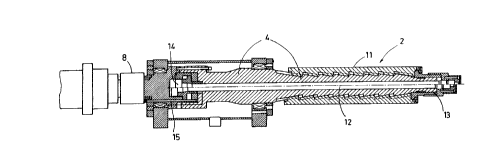
Fig. 2 shows the drum 2 in a partially spread and partially
despread position. The drum segments 11 are displaceable on the
toiler shaft 4 through a plunger 12 and a connecting flange 13.
The plunger 12 can be driven by a piston/cylinder unit 14 which is
connected through pressure medium lines 15, 15' to the rotary feed
8.
Fig. 3 shows the piston 16 and the cylinder 17 of the
7
CA 02255785 1998-11-23
piston/cylinder unit 14 integrated in the coiler shaft 4. The
cylinder 17 is held axially by the shaft extension 5. The piston
16 is connected through screws 18 to the plunger 12. The pressure
medium lines 15, 15', shown arranged one behind the other in Fig.
3, end in the cylinder spaces 19, 20. The piston 16 is sealed in
the cylinder 17 through sealing rings 21. Leakage oil lines 22
have the purpose of collecting any emerging leakage oil quantities
and to discharge them to an oil tank, not shown. If oil is
conducted in the leakage oil lines 22, this is a sign that the
sealing rings 21 are damaged.
Fig. 4 shows the shaft extension 5 on which the rotary feed 8 is
arranged. The rotary feed 8 is composed of a housing 23 in which
bushings 24, 25 are mounted. The bushings 24, 25 are mounted on a
sleeve 26 which surrounds the shaft extension 5.
Provided on the housing 23 is a connection 27 for the pressure
medium for the spreading procedure of the drum 2 as well as a
connection 28 for the pressure medium for despreading the drum 2.
In the area in which the connections 27, 28 overlap the bushings
24, 25, the bushings 24, 25 have annular ducts 29 which are
connected to annular ducts 31 through the discharge bores 30. The
annular ducts 31 are located opposite discharge bores 32 in the
sleeves 36. The discharge bores 32 end in the pressure medium
8
CA 02255785 1998-11-23
lines 15, 15'
The bushings 24 and 25 are mounted in the housing 23 through
0-rings 33. During operation, an oil film on which the bushing 24
floats is formed between the bushings 24 and sleeve 26. The oil
emerging between the bushing 24 and the sleeve 26 is collected by
a leakage oil line and is supplied to the oil tank, not shown.
The annular duct 31 of the bushing 25, which is located opposite
the connection 28 for despreading, may be without pressure during
the normal coiling operation. If a bushing corresponding to the
bushing 24 were to be used for the bushing 25, a certain pressure
would have to prevail during the coiling operation also in the
despreading line, so that the lubrication between the bushing and
the sleeve 26 is ensured.
However, the bushing 25 shown in Fig. 4 has additional annular
ducts 34, 35; 34' , 35' and radial bores 36; 36' through which a
pressure medium for maintaining the sliding film is conducted
continuously into the gap between the bushing 25 and the sleeve 26.
The connection 37 has the purpose of conducting the lubricant to
the bushing 25 in order to ensure in this manner the hydrostatic
support of the bushing 25 on the sleeve 26 without the requirement
that pressurized medium must be present at the connection 28. Of
9
CA 02255785 1998-11-23
course, a corresponding hydrostatic configuration could also be
provided for the bushing 24 or any additional bushings which are
not shown.
CA 02255785 1998-11-23
List of Reference Numerals
1 Coiler
2 Drum
3 Coil
4 Coiler Shaft
Shaft Extension
6 Shaft Coupling
7 Motor
8 Rotary Feed
9 Guide
1 Push Member
11 Drum Segments
12 Plunger
13 Connecting Flange
14 Piston/Cylinder Unit
Pressure Medium Line
16 Piston
17 Cylinder
18 Screw
19 Cylinder Space
Cylinder Space
21 Sealing Ring
22 Leakage Coil Line
23 Housing
24 Bushing
.Bushing
26 Sleeve
27 Connection
28 Connection
29 Annular Duct
Radial Bore
31 Annular Duct
~ CA 02255785 1998-11-23
32 Discharge Bore
33 0-Ring
34 Annular Duct
35 Annular Duct
36 Radial Bore
37 Connection