Note : Les descriptions sont présentées dans la langue officielle dans laquelle elles ont été soumises.
CA 02256615 1998-11-25
WO 97/48853 PCT/FI97/00384
1
Method and device in connection with impingement
drying and/or through-drying of a paper web or of
an equivalent web-like material
The invention concerns a method in connection with impingement drying and/or
through-drying of a paper web or of an equivalent web-like material, in which
method the paper web or the equivalent web-like material is dried by blowing
hot air
and/or superheated steam and/or equivalent by means of an impingement drying
device substantially perpendicularly to the paper web or the equivalent web-
like
material, in which method the paper web is passed on support of a wire or
equival-
ent past the impingement drying device.
Also, the invention concerns a device in connection with impingement drying
and/or
through-drying of a paper web or of an equivalent web-like material, which
device
comprises an impingement drying and/or through-drying device/devices, past
which
the web to be dried has been fitted to pass on support of a wire or
equivalent.
It is known from the prior art to use various impingement-drying/through-
drying
units for evaporation drying of a paper web, in which units the paper web is
dried
so that, by means of the impingement drying devices, hot air or superheated
steam
is blown substantially perpendicularly to the paper at a relatively high
speed. In these
solutions the paper web or an equivalent web-like material often reins on
support of
a wire, roll, cylinder or equivalent. With respect to the prior-art solutions
related to
evaporation drying of a paper web and based on impingement drying, reference
can
be made to the US Patent 4, 361, 466, in which a web drying method and an
equip-
ment that employ hot air are described, and to the US Patent S, 210, 958, in
which an
equipment and a method for drying of a paper web are described in which super-
heated steam is employed.
CA 02256615 1998-11-25
WO 97/48853 PCT/FI97/00384
2
As is known from the prior art, the use of superheated steam as the drying
medium
is more advantageous than the use of hot air, because in such a case it is
also
possible to utilize the hot moisture separated from the web. When paper is
dried by
means of superheated steam, it is known from the prior art to use devices in
which
the paper web runs on support of a wire and in which, at the side of the paper
web,
an impingement dryer is placed which includes steam blow openings and exhaust
openings for the return steam, and in which the area of the impingement dryer
has
been formed as a closed space by means of an enclosure. Inside the enclosure,
there
can also be several separate dryers. The closed space in the interior of the
enclosure
is, as a rule, filled with a steam whose temperature is somewhat higher than
100 °C.
Compared with conventional impingement drying processes provided with an
impingement drying hood, an advantage of an enclosed arrangement is that the
number of potential leakage points is minimized to two, i.e. the point at
which the
paper web is passed into the enclosure and the point at which the paper web is
passed out of the interior of the enclosure.
The prior-art solutions involve, among other things, the drawback that, with
such an
enclosure, there should not occur any web breaks or equivalent in the interior
of the
enclosure, because entering into the interior of the enclosure for repair
and/or
maintenance operations requires a time-consuming stage of emptying of steam
and
a period of cooling of the equipment and, after the maintenance or cleaning, a
long
start-up period, during which period the air must be removed and the equipment
is
heated to the operation temperature, which in itself lowers the capacity of
the
equipment and causes expenses.
In the prior-art solutions, the paper web often runs on support of a wire, and
the
web is kept in contact with the wire by means of a difference in pressure
across the
wire, but the drying-air jets of the impingement drying are in themselves
insufficient
for producing this difference in pressure, because the process between the
nozzle
face and the paper is somewhat dynamic, in which connection the paper web can
be
separated from the wire.
CA 02256615 1998-11-25
WO 97/48853 PCT/FI97100384
3
In the prior art, mechanical seals have been suggested as a solution, which
seals
permit the maintaining of a certain difference in pressure between the top and
bottom
portions of the enclosure. Mechanical seals are, however, not favourable,
because
they drag against the wire and, thus, wear the wire. Further, the use of
mechanical
seals has the consequence that said difference in pressure must be maintained
over
the length of the entire enclosure from the inlet opening of the paper to the
outlet
opening, because cross-direction additional seals for maintaining a difference
in
pressure make the equipment considerably more complex. This is why, at the
inlet
and outlet openings of the enclosure, there is a pressure above the wire
and/or a
vacuum below the wire, which can, however, result in leakage of steam out of
the
enclosure above the wire or in flow of air into the enclosure below the wire
at said
openings if the solution of sealing the openings for the web is not fully
sealed.
Further, alignment of a mechanical seal is difficult, because the seal must
coincide
with the edge of the paper web with adequate precision, which is very
difficult to
accomplish under production conditions. If leakage occurs through the wire
outside
the edges of the paper web, the result is a reduced difference in pressure or
a steam
flow from the top side to the bottom side.
Besides sealing, further important factors in applications of impingement
drying of
a paper web or of an equivalent web-like material, from the point of view of
runnability, include the keeping of the web substantially straight and the
distance of
the web from the blow devices. In order to control the running of the web, it
is
known to use a suction box placed underneath the wire, but the faces of the
suction
box that drag against the wire as well as the exhaust suction produced by the
suction
box cause problems for the runnability of the web and affect its stability on
the face
of the wire.
With respect to the prior art related to the present invention, reference can
also be
made to the applicant's FI Patent 67,107 (equivalent to US Patent No. 4, 551,
203),
in which an arrangement is described for passing a paper web from the press
section
into the dryer section, in which, to the side of the drying wire that supports
the web,
CA 02256615 2004-09-09
4
a number of air jets are blown at a speed substantially higher than the speed
of
the drying wire, the outlet direction of said jets being substantially the
same as
the running direction of the drying wire at said location, and air is ejected
by
means of said blowing of air out of the space placed between the drying wire
and
the wall placed in connection with the members that produce said air jets. In
this
arrangement, blow boxes have been employed, which are fitted on the run of
said drying wire at the side of said wire, which extend substantially across
the
entire width of the web, which include one or several nozzle slots, and in
which
blow boxes the walls placed facing the run of the drying wire are plane and
substantially parallel to the run of the drying wire.
The present invention is directed towards the provision of a solution by whose
means, in impingement drying, in particular in a system accomplished by means
of superheated steam, the runnability can be secured.
The invention is further directed towards the provision of a solution in which
the
problems and drawbacks described above do not occur.
In. accordance with one aspect of the present invention, there is provided a
method of impingement drying and/or through-drying of a web-like material in
which method the web is dried by blowing hot air and/or superheated steam by
means of an impingement drying device substantially perpendicularly to the
web, and in which method the paper web is passed on support of a wire past the
impingement drying device wherein, in an area of the impingement drying
device, the web and the wire are supported from the side of the wire which is
not
in contact with the web by the intermediate of jets produced by means of a
vacuum blow box/boxes substantially across the entire width of the web; first
jets produced by means of the vacuum blow box/boxes are blown at a speed
substantially higher than the speed of the drying wire, an outlet direction of
the
jets is substantially the same as the running direction of the drying wire in
the
area; and by means of the first jets stream and/or air is/are ejected out of
the
space between the wire and a wall of the blow box/boxes that produce the jets;
CA 02256615 2004-09-09
second jets produced by means of the blow box/boxes are blown in the direction
opposite to the running direction of the wire so as to seal an area of vacuum
between the wire and the blow box/boxes; and substantially the same medium is
used as the blow medium in the blow box/boxes as is used in the impingement
5 drying device.
In accordance with another aspect of the present invention, there is provided
a
device for impingement drying and/or through-drying of a web-like material,
which device comprises an impingement drying and/or through-drying
device/devices, past which the web to be dried is fitted to pass on support of
a
wire, wherein the device further comprises a vacuum blow box/boxes in view of
supporting the web and the wire by means of jets produced by means of the
vacuum blow box/boxes substantially across the entire width of the web; the
vacuum box/boxes are arranged in an area of the impingement drying and/or
through-drying device/devices on the side of the wire which is not in contact
with the web; that the vacuum blow box/boxes have nozzle slots by whose
means fist jets are blown in the running direction of the drying wire and by
whose means second jets are blown in the opposite direction to the running
direction of the drying wire; and the blow medium in the vacuum blow
boxlboxes is substantially the same medium as the blow medium in the
impingement-drying/through-drying device/devices.
In accordance with the invention, at the opposite side of the paper web or an
equivalent web-like material and the wire, opposite in relation to the
impingement dryer, vacuum blow boxes are placed, i.e. blow devices by whose
means a vacuum is produced below the wire, said vacuum blow devices
generating the necessary difference in pressure across the wire, in which
connection the paper web remains in contact with the wire and the runnability
is
secured.
In the present invention it has been realized, in a novel way, in view of
securing
the runnability, to combine an impingement drying application with vacuum
CA 02256615 2004-09-09
5a
blow boxes, by whose means the keeping of the web on the wire is secured and
by whose means, at the same time, the desired distance of the web from the
impingement drying devices and the control of said distance can be achieved,
in
which connection the efficiency of evaporation can also be controlled. In this
S way, by means of the arrangement in accordance with the invention, the
desired
draw of the paper web through the enclosure in the impingement drying unit is
achieved.
By means of the arrangement in accordance with the invention, a sealing
arrangement free of contact is achieved, in which there are no faces that drag
against the wire or against the paper web. The blower in the system of
runnab~lity in accordance with the invention can also be used for emptying the
enclosure from steam in a running-down situation, for example, for
maintenance,
and for evacuating air during a start-up procedure without having to use
separate
devices.
CA 02256615 1998-11-25
WO 97/48853 PCT/FI97/00384
6
When the web is dried by means of superheated steam, in the vacuum blow
devices
steam is used as the blow medium, which steam is preferably taken from the
interior
of the enclosure, primarily from below the wire in order that disturbing flows
should
not arise in the vertical direction in the enclosure. If necessary, in the
steam supply
line for the blow boxes there is a heating device, for example a steam heat
exchanger or a direct supply of fresh steam, so as to maintain a suitable
temperature
level and, thus, to eliminate any risk of condensing. In connection with the
arrange-
ment in accordance with the invention, it is also preferable to apply a system
of
control of runnability and steam status, wherein, by means of a blower, steam
is also
sucked from above the paper web and the wire and the same amount of steam is
fed
back after it has been heated. In order to maintain the temperature level in
the
enclosure, the heating device provided in the system of runnability is
probably
adequate, and no other heating or supply of steam into the enclosure is
needed.
In the following, the invention will be described in more detail with
reference to the
figures in the accompanying drawing, the invention being, however, not
supposed to
be strictly confined to the details of said illustrations.
Figure 1 is a schematic illustration of an arrangement of runnability in
accordance
with the invention in connection with impingement drying.
Figure 2 is a schematic illustration of a group of two blow boxes for use in
connec-
tion with the arrangement in accordance with the invention.
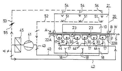
In the exemplifying embodiment shown in Fig. 1, the paper web W is dried by
means of an impingement dryer 10, whose surrounding area is enclosed both
above
the paper web W and below the wire F by means of a box 20. From the impinge-
ment dryer 10, superheated steam is blown towards the paper web W, which runs
on
support of the wire F. The enclosure 20 forms a closed space 21, which is open
at
the point A, at which the web W enters into said enclosed space 21, and at the
point
B, at which the web W departs from the closed space 21. Said points A,B of
passage
of the web W are provided with support and sealing members 22A,22B.
CA 02256615 1998-11-25
WO 97/48853 PCT/FI97/00384
7
In the space 21 in the interior of the enclosure 20, underneath the wire F, a
number
of vacuum blow devices 30 are fitted. By means of the vacuum blow boxes 30 the
run of the wire F and of the web W is stabilized, and thereby the runnability
of the
web W past the impingement dryer 10 and through the enclosure 20 is improved.
As is shown in Fig. 2, out of the blow boxes 30 placed at the wire F side,
steam
and/or air jets S 1 are blown substantially in the running direction of the
wire F, and
the speed of said jets Sl is substantially higher than the speed of the wire
F. As is
well known, the moving wire F carries steam/air along with it. If the area
from
which the wire F takes steam/air along with it can be sealed, a vacuum is
produced
in said area. In the method of the present invention, the sealing is carried
out by
means of blowings. Since the speed of the jets S1 is higher than the speed of
the
wire F, an ejection effect is produced, which enhances the vacuum produced by
the
pumping in the wire F. The sealing of the vacuum area in the other direction
takes
place by means of steam and/or air jets S2.
By the effect of the area subject to a vacuum formed between 27 the blow boxes
30
and the wire F, the steam/air attempts to flow through the wire F. Since the
web W
is practically impenetrable by air, the web W adheres tightly onto the wire F,
and no
detrimental fluttering occurs. Thus, the blow boxes stabilize the run of the
wire F
and of the web W in the area of the impingement dryer 10.
In Fig. 1, the number of the blow boxes 30 is three groups of two blow boxes
30
placed one after the other, and in the gaps between said groups guide rolls 23
are
placed. Depending on the geometry of the impingement dryer 10, there can be
one
or several blow boxes. Said blow boxes have a plane top face 28, which is
placed at
a distance O from the drying wire F that runs facing said face 28. Said
distance O
is preferably in the range of 5...30 mm. At both ends of the plane wall 28 in
the
blow boxes 30 there are nozzle slots 29, by whose means the blowings S 1 and
S2
described above are produced. There may also be nozzles at the edges of the
blow
boxes 30, the access of steam/air between the box and the wire being sealed by
means of blowings produced by means of said edge nozzles.
CA 02256615 1998-11-25
WO 97/48853 PCT/FI97/00384
8
As is shown in Figs. 1 and 2, the steam needed by the blow boxes 30 is taken
into
the ducts 18 from the space 21 in the interior of the enclosure 20, preferably
from
the portion below the wire F, in order that disturbing vertical flows should
not arise
inside the enclosure 20. From the ducts 18 the steam is passed along a duct 40
provided with a regulator 43 to the blower 41. By means of the blower 41,
along the
blow line 42, the steam is passed into each blow device 30 through the ducts
17, in
which ducts regulators 44 have been fitted so as to regulate the blowing in
each
device 30. The blow line 42 can also include a heating device 45, for example
a
steam heat exchanger or a device for direct supply of steam, in which case a
suitable
temperature level can be maintained in the interior 21 of the enclosure 20 in
order
to eliminate any risk of condensation.
By means of the blower 41, it is also possible to suck steam from the interior
21 of
the enclosure 20 from above the wire F and the web along the ducts 51,52 and
to
feed steam back, after it has been heated, along the ducts 53,54. The duct 53
is
provided with a regulation member 55 for regulation of the quantity of the
steam to
be supplied. When the interior 21 of the enclosure has to be emptied of steam,
for
example, for servicing of the dryer unit, the enclosure 20 is emptied of steam
by
means of the blower 41, and similarly, during the start-up stage of the
equipment,
air can be removed through the blower 41 and the ducts 18,40 from the interior
21
of the enclosure 20.
Above, the invention has been described with reference to an exemplifying
embodi-
ment in which steam is used as the drying medium in the impingement dryer 10.
The
arrangement in accordance with the invention can also be applied, with the
principles
described above, in arrangements in which hot air or equivalent is used as the
drying
medium in the impingement dryer unit 10.
Above, the invention has been described with reference to one preferred
embodiment
of same only, the invention being, yet, not supposed to be strictly confined
to the
details of said embodiment. Many variations and modifications are possible
within
the scope of the inventive idea defined in the following patent claims.