Sélection de la langue

Search

Sommaire du brevet 2257047 

Énoncé de désistement de responsabilité concernant l'information provenant de tiers

Une partie des informations de ce site Web a été fournie par des sources externes. Le gouvernement du Canada n'assume aucune responsabilité concernant la précision, l'actualité ou la fiabilité des informations fournies par les sources externes. Les utilisateurs qui désirent employer cette information devraient consulter directement la source des informations. Le contenu fourni par les sources externes n'est pas assujetti aux exigences sur les langues officielles, la protection des renseignements personnels et l'accessibilité.

Disponibilité de l'Abrégé et des Revendications

L'apparition de différences dans le texte et l'image des Revendications et de l'Abrégé dépend du moment auquel le document est publié. Les textes des Revendications et de l'Abrégé sont affichés :

  • lorsque la demande peut être examinée par le public;
  • lorsque le brevet est émis (délivrance).
(12) Brevet: (11) CA 2257047
(54) Titre français: CIRCUIT DE SORTIE AUDIO/VIDEO AUTOMATIQUE AVEC ENTREES AUDIO/VIDEO MULTIPLES
(54) Titre anglais: AUTO AUDIO/VIDEO OUTPUT CIRCUIT WITH MULTIPLE AUDIO/VIDEO INPUTS
Statut: Périmé et au-delà du délai pour l’annulation
Données bibliographiques
(51) Classification internationale des brevets (CIB):
  • G11B 31/00 (2006.01)
  • H04N 05/44 (2011.01)
  • H04N 05/46 (2006.01)
  • H04N 05/775 (2006.01)
(72) Inventeurs :
  • HO, CHIN-CHI (Taïwan, Province de Chine)
(73) Titulaires :
  • JOIN COMPUTER CO., LTD.
(71) Demandeurs :
  • JOIN COMPUTER CO., LTD. (Taïwan, Province de Chine)
(74) Agent: SMART & BIGGAR LP
(74) Co-agent:
(45) Délivré: 2002-08-27
(22) Date de dépôt: 1998-12-24
(41) Mise à la disponibilité du public: 2000-06-24
Requête d'examen: 2001-02-08
Licence disponible: S.O.
Cédé au domaine public: S.O.
(25) Langue des documents déposés: Anglais

Traité de coopération en matière de brevets (PCT): Non

(30) Données de priorité de la demande: S.O.

Abrégés

Abrégé anglais


An auto audio/video output circuit with multiple audio/video
inputs, the circuit having an analog/digital converter unit for convert
inputted video signal into digital signal, a CPU for memorizing the
sequence of inputted audio/video signals, permitting the last
inputted audio/video signal to be outputted to audio/video output
amplifiers for amplification and further output to a TV.

Revendications

Note : Les revendications sont présentées dans la langue officielle dans laquelle elles ont été soumises.


What the invention claimed is:
1. An auto audio/video output circuit comprising:
a video input interface having a plurality of signal input
terminals for receiving video signal from at least one audio/video
equipment, and a plurality of signal output terminals;
at least one audio input interface each having a plurality of
signal input terminals for receiving audio signal from at least one
audio/video equipment and a plurality of signal output terminals;
at least one analog/digital converter respectively connected
to the signal output terminals of said video input interface for
converting video signal into corresponding digital signal;
a CPU (central processing unit) having a plurality of signal
input pins respectively connected to respective signal output
terminals of said at least one analog/digital converter for receiving
converted digital signals from said analog/digital converter,
permitting received digital signals to be memorized in proper order
in memory means in said CPU, and a control signal output pin;
an analog electronic switch unit having a plurality of signal
input terminals respectively connected to the signal output terminals
of said video input interface and the signal output terminals of said
at least one audio input interface, a plurality of signal output
terminals, and a control terminal connected to the control signal
8

output pin of said CPU to receive a control signal from said CPU for
controlling the closing/opening of the signal output terminals of said
electronic switch unit;
a video output amplifier having a plurality of video signal
input terminals respectively connected to the signal output terminals
of said analog electronic switch unit to receive video signals from
said analog electronic switch unit, and a video signal output terminal;
and
an audio output amplifier having a plurality of signal input
terminals respectively connected to the signal output terminals of
said analog electronic switch unit to receive audio signals from said
analog electronic switch unit and a plurality of audio signal output
terminals;
wherein the video signal output terminal of said video output
amplifier and the audio signal output terminals of said audio output
amplifier are respectively connected to the video input terminal and
audio input terminals of a TV for output.
2. An auto audio/video output circuit comprising:
a video input interface having a plurality of signal input
terminals for receiving video signal from at least one audio/video
equipment, and a plurality of signal output terminals;
at least one audio input interface each having a plurality of
9

signal input terminals for receiving audio signal from at least one
audio/video equipment and a plurality of signal output terminals;
at least one analog/digital converter respectively connected
to the signal output terminals of said video input interface for
converting video signal into corresponding digital signal;
a CPU (central processing unit) having a plurality of signal
input pins respectively connected to respective signal output
terminals of said at least on8 analog/digital converter for receiving
converted digital signals from said analog/digital converter,
permitting received digital signals to be memorized in proper order
in memory means in said CPU, and a control signal output pin;
an analog electronic switch unit having a plurality of signal
input terminals respectively connected to the signal output terminals
of said video input interface and the signal output terminals of said
at least one audio input interface, a plurality of signal output
terminals, and a control terminal connected to the control signal
output pin of said CPU to receive a control signal from said CPU for
controlling the closing/opening of the signal output terminals of said
electronic switch unit;
a video output amplifier having a plurality of video signal
input terminals respectively connected to the signal output terminals
of said analog electronic switch unit to receive video signals from
10

said analog electronic switch unit, and a video signal output terminal;
and
an audio output amplifier having a plurality of signal input
terminals respectively connected to the signal output terminals of
said analog electronic switch unit to receive audio signals from said
analog electronic switch unit and a plurality of audio signal output
terminals; and
a radio transmitter connected to the signal output terminals
of said analog electronic switch unit;
wherein the video signal output terminal of said video output
amplifier and the audio signal output terminals of said audio output
amplifier are respectively connected to the video input terminal and
audio input terminals of a TV, so that an audio/video signal set can
be provided to the connected TV or a radio receiver TV for output
after audio/video signals from audio/video equipment have been
inputted into said video input interface and said at least one audio
input interface.
3. An auto audio/video output circuit comprising:
a video input interface having a plurality of signal input
terminals for receiving video signal from at least one audio/video
equipment, and a plurality of signal output terminals;
at least one audio input interface each having a plurality of
11

signal input terminals for receiving audio signal from at least one
audio/video equipment and a plurality of signal output terminals;
at least one analog/digital converter respectively connected
to the signal output terminals of said video input interface for
converting video signal into corresponding digital signal;
a CPU (central processing unit) having a plurality of signal
input pins respectively connected to respective signal output
terminals of said at least one analog/digital converter for receiving
converted digital signals from said analog/digital converter,
permitting received digital signals to be memorized in proper order
in memory means in said CPU, and a control signal output pin;
an analog electronic switch unit having a plurality of signal
input terminals respectively connected to the signal output terminals
of said video input interface and the signal output terminals of said
at least one audio input interface, a plurality of signal output
terminals, and a control terminal connected to the control signal
output pin of said CPU to receive a control signal from said CPU for
controlling the closing/opening of the signal output terminals of said
electronic switch unit;
a video output amplifier having a plurality of video signal
input terminals respectively connected to the signal output terminals
of said analog electronic switch unit to receive video signals from
12

said analog electronic switch unit, and a video signal output terminal;
and
an audio output amplifier having a plurality of signal input
terminals respectively connected to the signal output terminals of
S said analog electronic switch unit to receive audio signals from said
analog electronic switch unit and a plurality of audio signal output
terminals;
a radio transmitter connected to the signal output terminals
of said analog electronic switch unit; and
a Y/C signal separator connected to the signal output
terminals of said analog electronic switch unit;
wherein the video signal output terminal of said video output
amplifier and the audio signal output terminals of said audio output
amplifier are respectively connected to the video input terminal and
audio input terminals of a TV, so that an audio/video signal set can
be provided to the connected TV, a radio receiver TV, or a S terminal
TV for output after audio/video signals from audio/video equipment
have been inputted into said video input interface and said at least
one audio input interface.
4. The auto audio/video output circuit of claim 1 further
comprising a time delay circuit connected between said at least one
analog/digital converter and said CPU to extend the digital signals
13

transmitted from said least one analog/digital converter to said CPU.
5. The auto audio/video output circuit of claim 2 further
comprising a time delay circuit connected between said at least one
analog/digital converter and said CPU to extend the digital signals
transmitted from said least one analog/digital converter to said CPII.
6. The auto audio/video output circuit of claim 3 further
comprising a time delay circuit connected between said at least one
analog/digital converter and said CPU to extend the digital signals
transmitted from said least one analog/digital converter to said CPU.
14

Description

Note : Les descriptions sont présentées dans la langue officielle dans laquelle elles ont été soumises.

CA 02257047 1998-12-24
AUTO AUDIU/VIDEO OUTPUT CIRCUIT WITIi MULTIPLE
AUDIO/VIDEO INPUTS
BACKGROUND OF THE INVENTION
The present invention relates to an auto audio/video output
circuit with multiple audio/vidco inputs, and more particularly
such an auto audio/video output circuit which receives inputted
audio/video signals from different audio/video equipment, and
selects the last inputted audio/video signal for output.
A regular audio/video output device, for example a TV, has
only one set of audio/video input terminals. When connecting
different audio/video equipment to a TV, a selector shall be used and
connected between the TV and the audio/video equipment, so that
the user can select one audio/video equipment for output to the TV.
Further, a variety of audio/video equipment including DVD, VDC,
video tape recorder/player, V8, video cassette recorder, etc. have
been developed, and have ' appeared on the market. Various
adapters are known, and used for connection between different
audio/video equipment. These adapters are commonly made from
wave band switches or wave link switches. Because these switches
are passive devices, they cannot automatically set the output signal
channel. When in use, the user have to find the accurate output
channel for signal output. Because these switches are mechanical

CA 02257047 1998-12-24
devices, they wear quickly with use. There are also known
remote-controlled audio/video adapters for controlling the
connection between audio/video equipment. 'These remote-
controlled audio/video adapters are convenient in use, however their
manufacturing cost is high.
SUMMARY OF THE INVENTION
The present invention has been accomplished under the
circumstances in view. It is the main object of the present
invention to provide an auto audio/video output circuit with multiple
audio/video inputs which receives audio/video input signals from
different audio/video equipment, and automatically replaces the
previously inputted audio/video signal with the last inputted
audio/video signal for output, and automatically catches the
previously inputted audio/video signal (if not turned off) when the
last inputted audio/video signal is turned off. It is another object of
the present invention to provide an auto audio/video output circuit
with multiple audio/video inputs which is an electronic circuit
without mechanical switch means.
BRIEF DESCRIPTION OF THE DRAWINGS
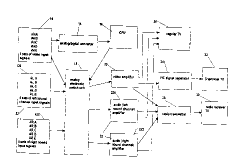
Figure 1 is a circuit block diagram of the present invention.
Figure 2 is a detailed circuit diagram of the present
invention.
2

CA 02257047 1998-12-24
Figure 3 shows an output state of the present invention
where only one audio/video equipment is turned on.
Figure 4 shows an output state of the present invention
where multiple audio/video equipment are turned on.
S Figure 5 is a circuit block diagram of an alternate form of the
present invention.
DETAILED DESCRIPTION OF THE PREFERRED EMBODIMENT
Referring to Figures I and 2, an auto auto-video output
circuit in accordance with the present invention is generally
comprised of a video input interface 10, an audio input interface 12
including a left sound channel input interface 120 and a right sound
channel input interface 122, an analog/digital converter 14, a CPU
(central processing unit) 16, an analog electronic switch unit 18, a
video output amplifier 20, and an audio output amplifier unit 22
IS including a left sound channel amplifier 220 and a right sound
channel amplifier 222.
'The video input interface 10 has a plurality of input
terminals VinA;VinB;VinC;VinD;VinE for receiving video signals
from a plurality of audio/video equipment, and a plurality of output
terminals respectively connected to input terminals of the
analog/digital converter 14 and input terminals of the analog
electronic switch unit 18. Video signals from the audio/video
3

CA 02257047 1998-12-24
equipment are respectively transmitted to the analog/digital
converter 14, and converted into corresponding digital signals.
The analog/digital converter 14 is comprised of a plurality of analog
to digital converting ICs (see US in Figure 2). The analog to digital
converting ICs of the analog/digital converter 14 receive video
output signals from the output terminals of the video input interface
10. When one analog to digital converting IC of the analog/digital
converter 14 receives a video output signal from the corresponding
output terminal of the video input interface 10, it provides a high
potential output signal to a~respective video input pin at the CPU 16
(see U6 in Figure 2). When several audio/video equipment are
turned on, the video signals are transmitted in proper order to the
respective video input pins of the CPU 6 through the video input
interface 10 via the analog/digital converter 14, and then stored in
internal memory means in the CPU 6, and the video signal from the
audio/video equipment which was last turned on is selected and
processed for output (this will be described further).
The input terminals of the left sound channel input interface
120 and the right sound channel input interface 122 of the audio
input interface 12 are respectively connected to the left sound
channel output terminals and right sound channel output terminals of
the audio/video equipment. The output terminals of the left sound
4

CA 02257047 1998-12-24
channel input interface 120 and the right sound channel input
interface 122 of the audio input interface 12 are respectively
connected to the respective input terminals of the analog electronic
switch unit 18. Input signals VinA ~ ALA ~ ARA;VinB
ALB ~ ARB;VinC ~ ALC - ARC;VinU - ALU ~ ARU;VinE ~
ALE ~ ARE from the video input interface 10 and the audio input
interface 12 are respectively connected to respective input terminals
of the analog electronic switch unit 18.
The output terminals of the analog electronic switch unit 18
are respectively connected to the input terminals of the video output
amplifier 20, the left sound channel amplifier 220 and the right
sound channel amplifier 222. T'he analog electronic switch unit 18
has a control terminal connected to one output pin of the CPU 16.
When the CPU 16 judges one input signal to be the last input signal,
it immediately outputs a control signal to the control terminal of the
analog electronic switch unit 18, causing the analog electronic
switch unit 18 to select the desired video signal ~ left/right sound
channel signal for output to the video output arnpllfier 20 or the
left/right sound channel amplifier 220(222).
When the user turns on one audio/video equipment, the
signal outputted from the audio/video equipment is detected by the
CPU 16, causing the analog electronic switch unit 18 to open the
5

CA 02257047 1998-12-24
corresponding output terminal, permitting the video signal to be
transmitted to the corresponding amplifier.
Referring to Figure 3 and Figure 2 again, when only one Av
signal (VinA ~ ALA ~ ARA) is inputted to the analog/digital
converter 14, the analog/digita) converter 14 catches one segment of
the video signal VinA from the inputted Av signal and converts it
into a high potential voltage signal, then outputs the high potential
voltage signal to the CPU 16, enabling the CI'U 16 to memorize the
video signal VinA as a first input signal. Alter the first input
signal has been memorized in memory means in the CPU 16, the CPU
16 immediately outputs a high potential to the analog electronic
switch unit 18 (the analog electronic switch unit 18 is comprised of
switching ICs U1;U2;U3;U4), causing it to output the selected
signal VinA ~ ALA ~ ARA to a regular TV 34 through the
amplifiers 20;220;222.
Referring to Figure 4 and Figure 2 again, when different
audio/video equipment are irregularly turned on at different times,
the CPU 16 memorizes the sequences of the inputted video signals
(see Figure 4) and let the last inputted audio/video signals (i.e.,
number 5) be transmitted the regular TV 34 through the amplifiers
20;220;222 (according to the present embodiment, these amplifiers
are transistor amplifier circuits).
6

CA 02257047 1998-12-24
Referring to Figure 1 again a transmitter circuit 26 may be
provided and connected to the output terminals of the video output
amplifier 20, the left sound channel amplifier 220 and the right
sound channel amplifier 222 for signal output by radio to a radio
receiver TV 30. Further, a Y/C signal separator 24 may be installed
to output amplified signals to a S terminal TV 32.
Figure 5 is a circuit block diagram of an alternate form of the
present invention, in which a time delay circuit 28 (RC circuit) is
connected between the analog/digital converter 14 and the CFU 16 to
extend the existing time of the high potential signals by means of a
charging discharging operation.
It is to be understood that the drawings are designed for
purposes of illustration only, and are not intended as a definition of
the limits and scope of the invention disclosed.

Dessin représentatif
Une figure unique qui représente un dessin illustrant l'invention.
États administratifs

2024-08-01 : Dans le cadre de la transition vers les Brevets de nouvelle génération (BNG), la base de données sur les brevets canadiens (BDBC) contient désormais un Historique d'événement plus détaillé, qui reproduit le Journal des événements de notre nouvelle solution interne.

Veuillez noter que les événements débutant par « Inactive : » se réfèrent à des événements qui ne sont plus utilisés dans notre nouvelle solution interne.

Pour une meilleure compréhension de l'état de la demande ou brevet qui figure sur cette page, la rubrique Mise en garde , et les descriptions de Brevet , Historique d'événement , Taxes périodiques et Historique des paiements devraient être consultées.

Historique d'événement

Description Date
Inactive : CIB du SCB 2022-09-10
Inactive : CIB expirée 2011-01-01
Inactive : CIB de MCD 2006-03-12
Le délai pour l'annulation est expiré 2004-12-24
Lettre envoyée 2003-12-24
Accordé par délivrance 2002-08-27
Inactive : Page couverture publiée 2002-08-26
Inactive : Page couverture publiée 2002-07-29
Inactive : Acc. récept. de corrections art.8 Loi 2002-07-24
Inactive : Taxe finale reçue 2002-06-14
Préoctroi 2002-06-14
Inactive : Transfert individuel 2002-05-30
Un avis d'acceptation est envoyé 2001-12-14
Lettre envoyée 2001-12-14
Un avis d'acceptation est envoyé 2001-12-14
Inactive : Approuvée aux fins d'acceptation (AFA) 2001-11-28
Lettre envoyée 2001-07-06
Inactive : Transfert individuel 2001-06-04
Lettre envoyée 2001-02-21
Inactive : Grandeur de l'entité changée 2001-02-20
Requête d'examen reçue 2001-02-08
Exigences pour une requête d'examen - jugée conforme 2001-02-08
Toutes les exigences pour l'examen - jugée conforme 2001-02-08
Inactive : Page couverture publiée 2000-07-12
Demande publiée (accessible au public) 2000-06-24
Inactive : Page couverture publiée 2000-06-23
Inactive : CIB en 1re position 1999-02-12
Symbole de classement modifié 1999-02-12
Inactive : CIB attribuée 1999-02-12
Inactive : Certificat de dépôt - Sans RE (Anglais) 1999-01-29
Demande reçue - nationale ordinaire 1999-01-28

Historique d'abandonnement

Il n'y a pas d'historique d'abandonnement

Taxes périodiques

Le dernier paiement a été reçu le 2001-12-21

Avis : Si le paiement en totalité n'a pas été reçu au plus tard à la date indiquée, une taxe supplémentaire peut être imposée, soit une des taxes suivantes :

  • taxe de rétablissement ;
  • taxe pour paiement en souffrance ; ou
  • taxe additionnelle pour le renversement d'une péremption réputée.

Les taxes sur les brevets sont ajustées au 1er janvier de chaque année. Les montants ci-dessus sont les montants actuels s'ils sont reçus au plus tard le 31 décembre de l'année en cours.
Veuillez vous référer à la page web des taxes sur les brevets de l'OPIC pour voir tous les montants actuels des taxes.

Historique des taxes

Type de taxes Anniversaire Échéance Date payée
Taxe pour le dépôt - petite 1998-12-24
TM (demande, 2e anniv.) - petite 02 2000-12-27 2000-12-22
Requête d'examen - générale 2001-02-08
Enregistrement d'un document 2001-06-04
TM (demande, 3e anniv.) - générale 03 2001-12-24 2001-12-21
2002-05-30
Taxe finale - générale 2002-06-14
TM (brevet, 4e anniv.) - générale 2002-12-24 2002-12-18
Titulaires au dossier

Les titulaires actuels et antérieures au dossier sont affichés en ordre alphabétique.

Titulaires actuels au dossier
JOIN COMPUTER CO., LTD.
Titulaires antérieures au dossier
CHIN-CHI HO
Les propriétaires antérieurs qui ne figurent pas dans la liste des « Propriétaires au dossier » apparaîtront dans d'autres documents au dossier.
Documents

Pour visionner les fichiers sélectionnés, entrer le code reCAPTCHA :


Pour visualiser une image, cliquer sur un lien dans la colonne description du document. Pour télécharger l'image (les images), cliquer l'une ou plusieurs cases à cocher dans la première colonne et ensuite cliquer sur le bouton "Télécharger sélection en format PDF (archive Zip)" ou le bouton "Télécharger sélection (en un fichier PDF fusionné)".

Liste des documents de brevet publiés et non publiés sur la BDBC .

Si vous avez des difficultés à accéder au contenu, veuillez communiquer avec le Centre de services à la clientèle au 1-866-997-1936, ou envoyer un courriel au Centre de service à la clientèle de l'OPIC.


Description du
Document 
Date
(aaaa-mm-jj) 
Nombre de pages   Taille de l'image (Ko) 
Dessins 1998-12-23 4 111
Description 1998-12-23 7 221
Revendications 1998-12-23 7 215
Abrégé 1998-12-23 1 13
Dessin représentatif 2000-07-10 1 12
Certificat de dépôt (anglais) 1999-01-28 1 163
Rappel de taxe de maintien due 2000-08-27 1 110
Accusé de réception de la requête d'examen 2001-02-20 1 179
Courtoisie - Certificat d'enregistrement (document(s) connexe(s)) 2001-07-05 1 112
Avis du commissaire - Demande jugée acceptable 2001-12-13 1 166
Avis concernant la taxe de maintien 2004-02-17 1 175
Correspondance 2002-06-13 1 45
Taxes 2000-12-21 1 41
Taxes 2001-12-20 1 49