Sélection de la langue

Search

Sommaire du brevet 2257682 

Énoncé de désistement de responsabilité concernant l'information provenant de tiers

Une partie des informations de ce site Web a été fournie par des sources externes. Le gouvernement du Canada n'assume aucune responsabilité concernant la précision, l'actualité ou la fiabilité des informations fournies par les sources externes. Les utilisateurs qui désirent employer cette information devraient consulter directement la source des informations. Le contenu fourni par les sources externes n'est pas assujetti aux exigences sur les langues officielles, la protection des renseignements personnels et l'accessibilité.

Disponibilité de l'Abrégé et des Revendications

L'apparition de différences dans le texte et l'image des Revendications et de l'Abrégé dépend du moment auquel le document est publié. Les textes des Revendications et de l'Abrégé sont affichés :

  • lorsque la demande peut être examinée par le public;
  • lorsque le brevet est émis (délivrance).
(12) Demande de brevet: (11) CA 2257682
(54) Titre français: MODULE A FIBRES OPTIQUES
(54) Titre anglais: FIBRE OPTIC MODULE
Statut: Réputée abandonnée et au-delà du délai pour le rétablissement - en attente de la réponse à l’avis de communication rejetée
Données bibliographiques
(51) Classification internationale des brevets (CIB):
  • G02B 6/42 (2006.01)
  • G02B 6/12 (2006.01)
(72) Inventeurs :
  • ISAKSSON, JAN (Suède)
(73) Titulaires :
  • MITEL SEMICONDUCTOR AB
(71) Demandeurs :
  • MITEL SEMICONDUCTOR AB (Suède)
(74) Agent: MARKS & CLERK
(74) Co-agent:
(45) Délivré:
(22) Date de dépôt: 1998-12-31
(41) Mise à la disponibilité du public: 1999-07-31
Requête d'examen: 1999-04-12
Licence disponible: S.O.
Cédé au domaine public: S.O.
(25) Langue des documents déposés: Anglais

Traité de coopération en matière de brevets (PCT): Non

(30) Données de priorité de la demande:
Numéro de la demande Pays / territoire Date
9802046.4 (Royaume-Uni) 1998-01-31

Abrégés

Abrégé anglais


An optical module comprising an optoelectronic board having electrical
connection
sites for connection with an electrical circuit. The module includes a
plurality of
optoelectronic devices on the optoelectronic board and an optical fiber
connector including
a plurality of optical elements each for connection with a respective
optoelectronic device.
Cooperative alignment members on the optoelectronic board and the optical
fiber
connector are provided for aligning the optoelectronic devices on the board.

Revendications

Note : Les revendications sont présentées dans la langue officielle dans laquelle elles ont été soumises.


THE EMBODIMENTS OF THE INVENTION IN WHICH AN EXCLUSIVE
PROPERTY OR PRIVILEGE IS CLAIMED ARE DEFINED AS FOLLOWS:
1. An optical module, comprising in combination:
a circuit board having electrical connection means for connection to a further
circuit;
an optoelectronic device mounted on said board, said optoelectronic device
including first alignment means; and
an optical fiber connector including an optical element for connection with
said
optoelectronic device, said connector including second alignment means for
cooperative
engagement with said first alignment means, whereby said optoelectronic device
and said
optical fiber connector are aligned together when said alignment means are
engaged.
2. The optical module as set forth in claim 1, wherein said at least one
optoelectronic device comprises an optical die.
3. The optical module as set forth in claim 1, wherein said optoelectronic
device comprises super luminescence diodes, surface emitting diodes, vertical
cavity
surface emitting diodes and transceiving detectors.
4. The optical module as set forth in claim 1, wherein said second alignment
means comprises guide pins on said fiber connector.
5. The optical module as set forth in claim 1, wherein said module includes
a plurality of optoelectronic devices, said devices arranged in parallel
relation.
6. The optical module as set forth in claim 5, wherein each optoelectronic
device of said plurality of optoelectronic devices includes a semiconductor.
7. The optical module as set forth in claim 1, wherein said optical fiber
connector comprises a fiber ferrule.

8. An optical module, comprising:
a circuit board for receiving components;
an optical die component having a frame therearound and alignment means in
said
frame; and
an optical fiber ferrule component containing optic fibers and including
second
alignment means for cooperative engagement with said first alignment means and
for
ensuring alignment of said die and said ferrule on said board.
9. The module as set forth in claim 8, wherein said optical die includes a
vertical cavity surface emitting laser.
10. The module as set forth in claim 8, wherein said circuit board includes a
plurality of electronic components.

Description

Note : Les descriptions sont présentées dans la langue officielle dans laquelle elles ont été soumises.

CA 02257682 1998-12-31
FIBER OPTIC MODULE
The present invention relates to a fiber optic module and more particularly,
the
present invention relates to a module where a plurality of optical elements
may be
mounted to an optoelectronic board.
Interconnection of optical fibers to optoelectronic assemblies has always been
problematic in the art. Connection between the fibers and optoelectronic
devices is
important for efficiency in the transmission of wavelength and power.
Imprecise alignment
causes aberrations in these parameters.
In view of the alignment difficulties known in the art, existing modules
present
limitations in terms of high costs and providing alignment and mounting
optoelectronic
devices on a circuit board. The present invention addresses these difficulties
and in
accordance with one aspect provides an optical module, comprising in
combination:
a circuit board having electrical connection means for connection to a further
circuit;
an optoelectronic device mounted on the board, the optoelectronic device
including
first alignment means; and
an optical fiber connector including an optical element for connection with
the
optoelectronic device, the connector including second alignment means for
cooperative
engagement with the first alignment means, whereby the optoelectronic device
and the
optical fiber connector are aligned together when the alignment means are
engaged.
In a further aspect of one embodiment of the present invention, there is
provided
an optical module, comprising:
a circuit board for mounting components;
an optical die component having a frame therearound and alignment means in the
frame; and
an optical fiber ferrule component containing optic fibers and including
second
alignment means for cooperative engagement with the first alignment means and
for
ensuring alignment of the die and the ferrule on the board.

CA 02257682 1998-12-31
2
The present invention facilitates connection of a series of electrical,
optical or other
optoelectronic elements to a circuit board, which board may then be integrated
into a
larger circuit, etc. Alignment between optical fiber connectors and
optoelectronic devices
is ensured by employing optoelectronic devices having a frame or die with
alignment
apertures. These apertures cooperatively engage other alignment members which
may
comprise pins or projections associated with the fiber connector.
It will be understood that the pins/projections may be associated with the
optoelectronic device as an alternative. Further, loose pins may also be
employed for
connection within apertures provided in the optoelectronic device and
connector.
Having thus generally described the invention, reference will now be made to
the
accompanying drawings illustrating preferred embodiments and in which:
Figure 1 is a plan view of one embodiment of an optoelectronic board for use
with
the present invention;
Figure 2 is a plan view of a lead frame for a flip chip mounted optical die;
Figure 3 is a plan view of a lead frame for a flip chip mounted optical array;
and
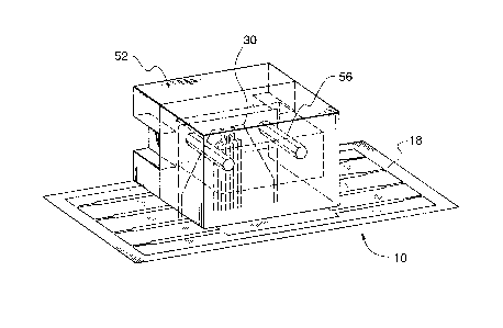
Figure 4 is a perspective view of one embodiment of a module in accordance
with
the present invention.
Similar numerals used in the text denote similar elements.
Referring now to the drawings, the electronic board 10 includes optoelectronic
devices 14 and other circuits (not shown) forming a module. The devices 14
each have
connection sites 18 for connection with an electrical circuit ( not shown ).
The electronic
board 10 includes alignment apertures 22 for alignment with optical elements
26 or 30

CA 02257682 1998-12-31
3
shown in Figures 2 and 3, respectively or for surface mounting of other
optoelectronic
devices.
Optical element 26 includes an optical die, e.g. a laser diode 34, having
contact
pads 38 and 42. A frame 36 surrounds die 34 and includes a lead frame 37. This
configuration facilitates flip chip bonding of the diode 34. Figure 3
illustrates an optical die
array. Each of the elements 26 and 30 include alignment apertures 46 and 48
for ensuring
alignment of the elements 26 and 30 with a fiber ferrule connector 52, shown
in Figure 4.
To this end, connector 52 includes guide pins 56 for cooperative engagement
within
apertures 46 and 48.
In terms of the optical elements, the same may comprise super luminescence
diodes, surface emitting diodes, vertical cavity surface emitting diodes as
well as others
known to those skilled in the art.
In addition to optoelectronic components, non-optical components may be
mounted commonly to the board 10 while facilitating alignment between ferrule
52 and
optical die 26.
In the case where the optical die array 30 is used, the ferrule 52 will carry
sufficient
optical elements for connection to a respective device.
Although embodiments of the invention have been described above, it is not
limited thereto and it will be apparent to those skilled in the art that
numerous
modifications form part of the present invention insofar as they do not depart
from the
spirit, nature and scope of the claimed and described invention.

Dessin représentatif
Une figure unique qui représente un dessin illustrant l'invention.
États administratifs

2024-08-01 : Dans le cadre de la transition vers les Brevets de nouvelle génération (BNG), la base de données sur les brevets canadiens (BDBC) contient désormais un Historique d'événement plus détaillé, qui reproduit le Journal des événements de notre nouvelle solution interne.

Veuillez noter que les événements débutant par « Inactive : » se réfèrent à des événements qui ne sont plus utilisés dans notre nouvelle solution interne.

Pour une meilleure compréhension de l'état de la demande ou brevet qui figure sur cette page, la rubrique Mise en garde , et les descriptions de Brevet , Historique d'événement , Taxes périodiques et Historique des paiements devraient être consultées.

Historique d'événement

Description Date
Le délai pour l'annulation est expiré 2003-12-31
Demande non rétablie avant l'échéance 2003-12-31
Réputée abandonnée - les conditions pour l'octroi - jugée non conforme 2003-02-10
Réputée abandonnée - omission de répondre à un avis sur les taxes pour le maintien en état 2002-12-31
Un avis d'acceptation est envoyé 2002-08-08
Lettre envoyée 2002-08-08
Un avis d'acceptation est envoyé 2002-08-08
Inactive : Approuvée aux fins d'acceptation (AFA) 2002-07-31
Modification reçue - modification volontaire 2002-06-18
Inactive : Dem. de l'examinateur par.30(2) Règles 2002-06-05
Inactive : Page couverture publiée 1999-08-06
Lettre envoyée 1999-08-03
Demande publiée (accessible au public) 1999-07-31
Inactive : Transfert individuel 1999-07-07
Modification reçue - modification volontaire 1999-05-18
Lettre envoyée 1999-05-07
Requête d'examen reçue 1999-04-12
Exigences pour une requête d'examen - jugée conforme 1999-04-12
Toutes les exigences pour l'examen - jugée conforme 1999-04-12
Inactive : CIB attribuée 1999-02-19
Symbole de classement modifié 1999-02-19
Inactive : CIB en 1re position 1999-02-19
Inactive : CIB attribuée 1999-02-19
Inactive : Correspondance - Formalités 1999-02-16
Inactive : Certificat de dépôt - Sans RE (Anglais) 1999-02-05
Exigences de dépôt - jugé conforme 1999-02-05
Demande reçue - nationale ordinaire 1999-02-03

Historique d'abandonnement

Date d'abandonnement Raison Date de rétablissement
2003-02-10
2002-12-31

Taxes périodiques

Le dernier paiement a été reçu le 2001-12-18

Avis : Si le paiement en totalité n'a pas été reçu au plus tard à la date indiquée, une taxe supplémentaire peut être imposée, soit une des taxes suivantes :

  • taxe de rétablissement ;
  • taxe pour paiement en souffrance ; ou
  • taxe additionnelle pour le renversement d'une péremption réputée.

Veuillez vous référer à la page web des taxes sur les brevets de l'OPIC pour voir tous les montants actuels des taxes.

Historique des taxes

Type de taxes Anniversaire Échéance Date payée
Taxe pour le dépôt - générale 1998-12-31
Requête d'examen - générale 1999-04-12
Enregistrement d'un document 1999-07-07
TM (demande, 2e anniv.) - générale 02 2001-01-01 2000-10-11
TM (demande, 3e anniv.) - générale 03 2001-12-31 2001-12-18
Titulaires au dossier

Les titulaires actuels et antérieures au dossier sont affichés en ordre alphabétique.

Titulaires actuels au dossier
MITEL SEMICONDUCTOR AB
Titulaires antérieures au dossier
JAN ISAKSSON
Les propriétaires antérieurs qui ne figurent pas dans la liste des « Propriétaires au dossier » apparaîtront dans d'autres documents au dossier.
Documents

Pour visionner les fichiers sélectionnés, entrer le code reCAPTCHA :


Pour visualiser une image, cliquer sur un lien dans la colonne description du document. Pour télécharger l'image (les images), cliquer l'une ou plusieurs cases à cocher dans la première colonne et ensuite cliquer sur le bouton "Télécharger sélection en format PDF (archive Zip)" ou le bouton "Télécharger sélection (en un fichier PDF fusionné)".

Liste des documents de brevet publiés et non publiés sur la BDBC .

Si vous avez des difficultés à accéder au contenu, veuillez communiquer avec le Centre de services à la clientèle au 1-866-997-1936, ou envoyer un courriel au Centre de service à la clientèle de l'OPIC.


Description du
Document 
Date
(aaaa-mm-jj) 
Nombre de pages   Taille de l'image (Ko) 
Dessin représentatif 1999-08-06 1 13
Abrégé 1998-12-31 1 14
Description 1998-12-31 3 113
Revendications 1998-12-31 2 52
Dessins 1998-12-31 2 48
Page couverture 1999-08-06 1 35
Dessins 1999-02-16 2 40
Revendications 2002-06-18 1 40
Certificat de dépôt (anglais) 1999-02-05 1 163
Accusé de réception de la requête d'examen 1999-05-07 1 179
Courtoisie - Certificat d'enregistrement (document(s) connexe(s)) 1999-08-03 1 139
Rappel de taxe de maintien due 2000-09-05 1 110
Avis du commissaire - Demande jugée acceptable 2002-08-08 1 164
Courtoisie - Lettre d'abandon (taxe de maintien en état) 2003-01-28 1 176
Courtoisie - Lettre d'abandon (AA) 2003-04-22 1 166
Correspondance 1999-02-09 1 33
Correspondance 1999-02-16 3 62