Sélection de la langue

Search

Sommaire du brevet 2257838 

Énoncé de désistement de responsabilité concernant l'information provenant de tiers

Une partie des informations de ce site Web a été fournie par des sources externes. Le gouvernement du Canada n'assume aucune responsabilité concernant la précision, l'actualité ou la fiabilité des informations fournies par les sources externes. Les utilisateurs qui désirent employer cette information devraient consulter directement la source des informations. Le contenu fourni par les sources externes n'est pas assujetti aux exigences sur les langues officielles, la protection des renseignements personnels et l'accessibilité.

Disponibilité de l'Abrégé et des Revendications

L'apparition de différences dans le texte et l'image des Revendications et de l'Abrégé dépend du moment auquel le document est publié. Les textes des Revendications et de l'Abrégé sont affichés :

  • lorsque la demande peut être examinée par le public;
  • lorsque le brevet est émis (délivrance).
(12) Brevet: (11) CA 2257838
(54) Titre français: TUBE DE VENTILATION, DESTINE PARTICULIEREMENT A DES DISPOSITIFS MEDICAUX
(54) Titre anglais: VENTILATION TUBE, PARTICULARLY FOR MEDICAL DEVICES
Statut: Périmé
Données bibliographiques
(51) Classification internationale des brevets (CIB):
  • A61M 16/00 (2006.01)
  • A61M 11/00 (2006.01)
  • A61M 16/08 (2006.01)
  • A61M 16/10 (2006.01)
  • F24H 1/14 (2006.01)
  • F24H 3/04 (2006.01)
(72) Inventeurs :
  • GIBERTONI, LUCIO (Italie)
  • BERGAMASCHI, PAOLO (Italie)
(73) Titulaires :
  • TYCO HEALTHCARE GROUP LP (Etats-Unis d'Amérique)
(71) Demandeurs :
  • MALLINCKRODT INC. (Etats-Unis d'Amérique)
(74) Agent: OSLER, HOSKIN & HARCOURT LLP
(74) Co-agent:
(45) Délivré: 2003-05-06
(86) Date de dépôt PCT: 1997-06-10
(87) Mise à la disponibilité du public: 1997-12-18
Requête d'examen: 1998-12-09
Licence disponible: S.O.
(25) Langue des documents déposés: Anglais

Traité de coopération en matière de brevets (PCT): Oui
(86) Numéro de la demande PCT: PCT/US1997/009770
(87) Numéro de publication internationale PCT: WO1997/047348
(85) Entrée nationale: 1998-12-09

(30) Données de priorité de la demande:
Numéro de la demande Pays / territoire Date
MI96U000435 Italie 1996-06-13

Abrégés

Abrégé français

Cette invention se rapporte à un tube de ventilation (1) chauffé comportant au moins un filament chauffant (4)(5) noyé à l'intérieur d'une arête hélicoïdale (3) courant le long de la paroi externe (2) dudit tube.


Abrégé anglais


A heated ventilation tube (1) having at least one heating wire (4, 5) embedded
in a helical ridge (3) along the outer wall (2).

Revendications

Note : Les revendications sont présentées dans la langue officielle dans laquelle elles ont été soumises.


5

CLAIMS

1. A ventilation tube for use with medical devices
comprising:
an elongate flexible, seamless, extruded plastic
conduit having a uniform inside diameter;
a helical plastic ridge formed on an outside diameter
of said conduit;
at least one wire conductor inserted directly in said
ridge while said ridge is being extruded to form an
electric resistor for heating a gas that flows inside the
tube.

2. The ventilation tube of claim 1 wherein said
ridge is formed from a plastic compound that is more rigid
than a plastic compound of said conduit.

3. The apparatus of claim 1 wherein said elongate
conduit has a proximal and distal end and said conductor is
formed as a loop with two free ends, the free ends located
at the proximal end of said conduit to connect to an
electric power source.

4. The apparatus of claim l, wherein said elongate
conduit is formed from a transparent plastic compound.

5. The ventilation tube of claim 1 wherein the wires
are uniformly embedded within the ridge to provide uniform
heating in all points of the electrical surface.

6. The ventilation tube of claim 5 wherein the wires
are made of copper.


6

7. The ventilation tube of claim 5 wherein the tube
is made of a PVC material that is transparent.

8. The ventilation tube of claim 6 wherein the tube
is made of a PVC material that is transparent.

9. A ventilation tube for use with medical devices
comprising:
an elongate flexible, seamless, extruded plastic
conduit having a uniform inside diameter;
a helical plastic ridge formed on an outside diameter
of said conduit, said conduit and ridge being formed in a
single extrusion process, said ridge being composed of
transparent PVC;
two copper wire conductors uniformly inserted directly
in said ridge while said ridge is being extruded to form an
electric resistor for heating a gas that flows inside the
tube.

10. A process for making a ventilation tube for use
with medical devices comprising:
simultaneously extruding an elongate flexible,
seamless, extruded plastic conduit having a uniform inside
diameter and a helical plastic ridge formed on an outside
diameter of said conduit;
inserting wire conductors uniformly in said ridge
while said ridge is being extruded to form an electric
resistor for heating a gas that flows inside the tube.

11. The process of claim 10 wherein the wires are
uniformly embedded within the ridge to provide uniform
heating in all points of the electrical surface.


7


12. The process of claim 11 wherein the wires are
made of copper.

13. The process of claim 10 wherein the tube is made
of a PVC material that is transparent.

Description

Note : Les descriptions sont présentées dans la langue officielle dans laquelle elles ont été soumises.


CA 022~7838 1998-12-09

W097l47348 PCT~S97/09770

VENTILATION TUBE, PARTICULA~LY FOR MEDICAL DEVICES
Technical Field
The present invention relates to a ventilation tube
particularly for medical devices.
Background art
In many medical devices and particularly in ventilation
tubes for intensive care, in ventilation tubes at the outlet
5 of humidifiers and the like, it is conventionally necessary
to heat the gaseous substance, generally air, that
circulates inside the tube.
An electric resistor is currently used to solve the
problem, said resistor being located inside the plastic
lO tube, so as to heat the air to prevent condensation of the
moisture contained therein.
This solution entails considerable drawbacks, since any
burns caused by the electric resistor on the tube wall might
generate fumes which would be fed to the patient, with the
15 obvious associated problems.
Another drawback is also constituted by the fact that a
resistor located inside the tube is unable to provide for
uniform heating of the inside walls of the tube and
therefore cold spots may form which constitute condensation
regions for the moisture that is present in ventilation
cases, accordingly creating regions in which water
accumulates and which, in addition to obstructing the useful
cross-section of the tube, also constitute regions for
bacterial growth.
In order to solve the above problem, ventilation tubes
are already commercially available in which an external wire
is provided which is wound in a spiral around the outer wall

CA 022~7838 1998-12-09


W O 97/47348 PCTAUS97tO9770
-- 2 --
of the tube; this solution is considerably expensive and
also causes problems, since it is necessary to provide for
an additional tube in order to sheath the resistor, both
owing to electrical insulation problems and in order to
prevent excessively hot spots from remaining on the outside,
possibly leading to problems for users.
This structure has the drawback that it is very heavy
and that it considerably reduces the transparency, lightness
and flexibility characteristics which are typical of a PVC
lo tube.
Another drawback resides in the costs, since the
sheathing of the tube, in addition to increasing the amount
of plastics being used, requires much more complex and
expensive production technologies than the ordinary spiral
tube.
Disclosure of the Invention
The aim of the present invention is to solve the above
problems, by providing a ventilation tube particularly for
medical devices which allows to provide uniform heating on
the entire surface of the tube affected by the flow of the
gaseous substance, thus helping to eliminate the regions
where liquid might condense.
Within the scope of this aim, a particular object of
the invention is to provide a ventilation tube in which the
heating element is not located inside the tube, so that any
burns do not produce fumes which are fed directly to the
patient, and is furthermore capable of maintaining the

flexibility, lightness and transparency characteristics of
the spiral tube substantially unchanged.
Another object of the present invention is to provide a

CA 022~7838 1998-12-09


W O 97/47348 PCTrUS97/09770
-- 3 --
ventilation tube which allows to obtain tubes which are
already equipped with the heating element, with the
possibility of performing extremely simple connections.
Another object of the present invention is to provide a
ventilation tube particularly for medical devices, which can
be easily obtained starting from commonly commercially
available elements and materials and which is also
competitive from a merely economical point of view.
Brief Description of the Drawings
This aim, these objects, and others which will become
apparent hereinafter are achieved by a ventilation tube
particularly for medical devices, illustrated only by way of
non-limitative example in the accompanying drawings,
wherein:
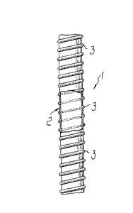
figure 1 is a partially cutout schematic view of a
15 portion of ventilation tube according to the present
invention;
figure 2 is an enlarged-scale sectional view of the
tube;
figure 3 is a view of the detail of the embedding of

the electric wires.
Ways of carrying out the Invention
With reference to the above figures, the ventilation
tube particularly for medical devices, according to the
invention, is generally designated by the reference numeral
1 and comprises a tubular body 2 made of flexible plastics,

such as PVC, which is externally provided with ridges formed
by a spiral ridge 3 which is rigidly coupled to the outer
surface of the tubular body 2 since it is formed in a single
extrusion process and is made of a more rigid plastics which


CA 022~7838 1998-12-09


W O 97/47348 PCTrUS97/09770
-- 4 --
allows to constitute the conventional spiral of a tube.
The particularity of the invention is constituted by
the fact that two mutually spaced electric wires 4 and 5 are
embedded directly inside the spiral ridge 3 and constitute
an electric resistor.
The two electric wires are not in mutual contact and in
practice the material that forms the ridge constitutes the
electrical insulation for the copper wires.
Advantageously, two electric wires are used so that by
lo simply joining them at one end an electric resistor is
obtained with the possibility of connecting the remaining
two ends to the electric power source.
The tubular body is advantageously made of transparent
plastics, so that the tube remains transparent, and the
15 direct insertion of the copper wires in the spiral ridge
allows to considerably contain the weight of the tube as
well as its manufacturing cost.
Another advantage obtained is constituted by the fact
that the uniform distribution of the wires that form the
electric resistor along the surface allows uniform heating
in all points of the electrical surface while having
excellent electrical safety characteristics, since the
electric wires are directly embedded in the ridge, which is
monolithic with the tube.
In practice, the materials employed, so long as they
are compatible with the specific use, as well as the
contingent shapes and dimensions, may be any according to

requirements.
Dessin représentatif
Une figure unique qui représente un dessin illustrant l'invention.
États administratifs

Pour une meilleure compréhension de l'état de la demande ou brevet qui figure sur cette page, la rubrique Mise en garde , et les descriptions de Brevet , États administratifs , Taxes périodiques et Historique des paiements devraient être consultées.

États administratifs

Titre Date
Date de délivrance prévu 2003-05-06
(86) Date de dépôt PCT 1997-06-10
(87) Date de publication PCT 1997-12-18
(85) Entrée nationale 1998-12-09
Requête d'examen 1998-12-09
(45) Délivré 2003-05-06
Expiré 2017-06-12

Historique d'abandonnement

Il n'y a pas d'historique d'abandonnement

Historique des paiements

Type de taxes Anniversaire Échéance Montant payé Date payée
Requête d'examen 400,00 $ 1998-12-09
Enregistrement de documents 100,00 $ 1998-12-09
Le dépôt d'une demande de brevet 300,00 $ 1998-12-09
Enregistrement de documents 100,00 $ 1999-02-17
Taxe de maintien en état - Demande - nouvelle loi 2 1999-06-10 100,00 $ 1999-02-17
Taxe de maintien en état - Demande - nouvelle loi 3 2000-06-12 100,00 $ 2000-04-26
Taxe de maintien en état - Demande - nouvelle loi 4 2001-06-11 100,00 $ 2001-06-01
Taxe de maintien en état - Demande - nouvelle loi 5 2002-06-10 150,00 $ 2002-05-24
Taxe finale 300,00 $ 2003-02-07
Taxe de maintien en état - brevet - nouvelle loi 6 2003-06-10 150,00 $ 2003-05-21
Taxe de maintien en état - brevet - nouvelle loi 7 2004-06-10 200,00 $ 2004-05-25
Taxe de maintien en état - brevet - nouvelle loi 8 2005-06-10 200,00 $ 2005-05-20
Taxe de maintien en état - brevet - nouvelle loi 9 2006-06-12 200,00 $ 2006-05-17
Taxe de maintien en état - brevet - nouvelle loi 10 2007-06-11 250,00 $ 2007-05-17
Taxe de maintien en état - brevet - nouvelle loi 11 2008-06-10 250,00 $ 2008-05-20
Taxe de maintien en état - brevet - nouvelle loi 12 2009-06-10 250,00 $ 2009-05-19
Taxe de maintien en état - brevet - nouvelle loi 13 2010-06-10 250,00 $ 2010-05-17
Taxe de maintien en état - brevet - nouvelle loi 14 2011-06-10 250,00 $ 2011-05-17
Enregistrement de documents 100,00 $ 2011-08-31
Taxe de maintien en état - brevet - nouvelle loi 15 2012-06-11 450,00 $ 2012-05-17
Taxe de maintien en état - brevet - nouvelle loi 16 2013-06-10 450,00 $ 2013-05-17
Taxe de maintien en état - brevet - nouvelle loi 17 2014-06-10 450,00 $ 2014-06-09
Taxe de maintien en état - brevet - nouvelle loi 18 2015-06-10 450,00 $ 2015-05-25
Taxe de maintien en état - brevet - nouvelle loi 19 2016-06-10 450,00 $ 2016-05-27
Titulaires au dossier

Les titulaires actuels et antérieures au dossier sont affichés en ordre alphabétique.

Titulaires actuels au dossier
TYCO HEALTHCARE GROUP LP
Titulaires antérieures au dossier
BERGAMASCHI, PAOLO
GIBERTONI, LUCIO
MALLINCKRODT INC.
MALLINCKRODT MEDICAL, INC.
Les propriétaires antérieurs qui ne figurent pas dans la liste des « Propriétaires au dossier » apparaîtront dans d'autres documents au dossier.
Documents

Pour visionner les fichiers sélectionnés, entrer le code reCAPTCHA :


Pour visualiser une image, cliquer sur un lien dans la colonne description du document. Pour télécharger l'image (les images), cliquer l'une ou plusieurs cases à cocher dans la première colonne et ensuite cliquer sur le bouton "Télécharger sélection en format PDF (archive Zip)" ou le bouton "Télécharger sélection (en un fichier PDF fusionné)".

Liste des documents de brevet publiés et non publiés sur la BDBC .

Si vous avez des difficultés à accéder au contenu, veuillez communiquer avec le Centre de services à la clientèle au 1-866-997-1936, ou envoyer un courriel au Centre de service à la clientèle de l'OPIC.


Description du
Document 
Date
(yyyy-mm-dd) 
Nombre de pages   Taille de l'image (Ko) 
Abrégé 1998-12-09 1 48
Page couverture 2003-04-01 1 30
Page couverture 1999-03-19 1 27
Dessins 1998-12-09 1 43
Description 1998-12-09 4 162
Revendications 1998-12-09 1 39
Revendications 2002-06-17 3 77
Dessins représentatifs 1999-03-19 1 6
Taxes 2000-04-26 1 43
Correspondance 2003-02-07 1 35
Poursuite-Amendment 2001-12-17 2 66
Poursuite-Amendment 2002-06-17 5 162
Cession 1998-12-09 7 225
PCT 1998-12-09 10 320
Correspondance 1999-02-16 1 32
Cession 1999-02-17 3 142
Taxes 1999-02-17 1 36
Cession 2011-08-31 61 2 239