Sélection de la langue

Search

Sommaire du brevet 2259627 

Énoncé de désistement de responsabilité concernant l'information provenant de tiers

Une partie des informations de ce site Web a été fournie par des sources externes. Le gouvernement du Canada n'assume aucune responsabilité concernant la précision, l'actualité ou la fiabilité des informations fournies par les sources externes. Les utilisateurs qui désirent employer cette information devraient consulter directement la source des informations. Le contenu fourni par les sources externes n'est pas assujetti aux exigences sur les langues officielles, la protection des renseignements personnels et l'accessibilité.

Disponibilité de l'Abrégé et des Revendications

L'apparition de différences dans le texte et l'image des Revendications et de l'Abrégé dépend du moment auquel le document est publié. Les textes des Revendications et de l'Abrégé sont affichés :

  • lorsque la demande peut être examinée par le public;
  • lorsque le brevet est émis (délivrance).
(12) Brevet: (11) CA 2259627
(54) Titre français: PROCEDE ET DISPOSITIF DE DESTRUCTION D'OBJETS
(54) Titre anglais: METHOD AND DEVICE FOR DESTRUCTION OF OBJECTS
Statut: Réputé périmé
Données bibliographiques
(51) Classification internationale des brevets (CIB):
  • E05G 1/14 (2006.01)
(72) Inventeurs :
  • LINDSKOG, KJELL (Suède)
  • FRISTROM, OLA (Suède)
(73) Titulaires :
  • SQS SECURITY QUBE SYSTEM AB (Suède)
(71) Demandeurs :
  • SQS SECURITY QUBE SYSTEM AB (Suède)
(74) Agent: RIDOUT & MAYBEE LLP
(74) Co-agent:
(45) Délivré: 2005-09-27
(86) Date de dépôt PCT: 1997-07-06
(87) Mise à la disponibilité du public: 1998-01-15
Requête d'examen: 2002-07-03
Licence disponible: S.O.
(25) Langue des documents déposés: Anglais

Traité de coopération en matière de brevets (PCT): Oui
(86) Numéro de la demande PCT: PCT/SE1997/001237
(87) Numéro de publication internationale PCT: WO1998/001646
(85) Entrée nationale: 1999-01-06

(30) Données de priorité de la demande:
Numéro de la demande Pays / territoire Date
9602732-1 Suède 1996-07-10

Abrégés

Abrégé français

L'invention concerne un procédé et un dispositif (1) de destruction d'objets (100) placés dans un conteneur de sécurité protégé par système d'alarme. On utilise un agent destructeur (50) qui se répand sur l'objet ou les objets (100) lorsque l'alarme est déclenchée, de façon à marquer et/ou détruire l'objet ou les objets. On utilise également un dispositif destructeur (1) contenant une substance explosive (60) qui agit au moins partiellement sur l'objet ou les objets (100) lorsque l'alarme est déclenchée. Le dispositif (1) comprend un canal (2) dont l'ouverture fait face à l'objet ou aux objets (100). L'agent destructeur (50) est encapsulé dans le canal (2) et la substance explosive (60) est disposée à proximité du canal. Le canal (2) a une section transversale en U et comprend des parois d'extrémité (6, 7).


Abrégé anglais


The invention relates to a method and to a device (1)
for destruction of objects (100) stored in an alarm-protected
security container. There is used a destructive agent (50) which
is distributed over the object or objects (100) when the alarm is
triggered, so as to mark and/or destroy the object/objects. There
is also used a destructive device (1) which includes an explosive
agent (60) that acts at least partially on the object/objects (100)
when the alarm is triggered. The device (1) includes a channel
(2) whose opening faces towards the object/objects (100). The
destructive agent (50) is encapsulated in the channel (2) and
the explosive agent (60) is disposed adjacent the channel. The
channel (2) has a generally U-shaped cross section and includes
end-walls (6, 7).

Revendications

Note : Les revendications sont présentées dans la langue officielle dans laquelle elles ont été soumises.


7

CLAIMS

1. A method of destroying objects stored in a security
container that includes an alarm device, wherewith the method
comprises the use of a destructive agent (50) which is
distributed over the object or objects (100) when said alarm
device is triggered, such as to mark and/or destroy the
object/objects, and wherewith there is used a destructive
device (1;1') that includes an explosive agent (60) which
acts at least partially on the object/objects (100) when said
alarm device is triggered, encapsulating the destructive
agent (50) in a channel (2;2') whose opening faces towards
the object/objects (100), placing said explosive agent (60)
adjacent said channel, characterized by using a channel
(2;2') which is generally U-shaped or reflectorlike in cross-
section and which includes end-walls (6,7; 6',7').

2. A device for destruction of objects stored in an alarm-
fitted security container, said device (1;1') including a
destructive agent (50) which is distributed over the object
or objects (100) when an alarm is triggered, such as to mark
and/or destroy the object/objects, and wherewith the
destructive device (1;1') includes an explosive agent (60)
which acts at least partially on the object/objects (100),
the device (1;1') includes a channel (2;2') whose opening
faces towards the object/objects (100), the destructive agent
(50) is encapsulated in the channel (2;2'), the explosive
agent (60) is disposed adjacent said channel, characterized
in that the channel (2;2') has a generally U-shaped or
reflectorlike cross-section; and in that said channel (2;2')
has end-walls (6,7; 6',7').


8

3. A device according to Claim 2, characterized in that the
channel (2;2') opening is covered with a grid or grating
structure (11;11').

4. A device according to Claim 2 or 3, characterized in
that the explosive agent (60) is a string of explosives.

5. A device according to any one of Claims 2-4,
characterized in that the explosive agent (60) is a pentyl
fuse.

6. A device according to any one of Claims 2-5,
characterized in that the destructive agent (50) is a single-
component liquid encapsulated in a casing (10;10').

7. A device according to any one of Claims 2-6,
characterized in that the destructive agent (50) is a two-
component liquid; and in that each liquid component is
encapsulated in a separate casing.

8. A device according to Claim 6 or 7, characterized in
that the casing element (10;10') encasing the destructive
agent is comprised of foil, for instance plastic foil.


Description

Note : Les descriptions sont présentées dans la langue officielle dans laquelle elles ont été soumises.


CA 02259627 2004-09-03 '
i
~~'HOD albTD DSVICE FOR 1788TRUCTION OP O$JSCTS
The present invention relateB t0 d method of destroying
' objects, The
invention also relates 'o a device fOr Carrying out the
method.
Security containers fox the transportation of valuables, such
as banycnotec for ~.nstarrce, will. normally contain a
1.0 destructive device in the form of dye releaBing cassettes Or
ampoules that are activated to release a dy2 when the
security caritainer ig manipulated unlawxully, therewith
colouring or otherwise destroying the Contents of the
container.
20
When tlae security container is filled with sealed, plastic
envelopes for ~.nstance, it is very diEf~.cuZt to achieve
satisfactory colouring of the contents of the envelopes, fo7c
instt~nce banknot~S .
An object: of the present invention is to provide a method and
a device wY~xch will cause destruction of the objects or
drGicles in the security container in a particularly
effective manner. This object is achieved by the present
invention. A method forms one aspect of the invention;
a device forms another aspect of the invention.
Some of the advantages afforded by the present invention are
listed below.
The inventive method and device cause the generation of an
impact wave which sp~.its open the envelapesjwrappinga and/or


CA 02259627 1999-O1-06
WO 98/01646 PCT/SE97/01237
2
the bundles of banknotes or other articles, such as to expose
a very large surface area to the destructive agent.
The destructive agent is also distributed highly effectively.
The inventive device may, for instance, accommodate both
single-component and multi-component destructive agents of
mutually different types. Agents that will destroy or render
useless magnetic tapes, diskettes and other information media
may, of course, be used in the inventive device.
The inventive device is not limited to any particular size or
dimensions and is adapted to the specifications required.
The inventive device also has technical and economical
advantages.
The invention will now be described in more detail with
reference to exemplifying embodiments thereof and also with
reference to the accompanying drawings, in which Fig'. 1 is a
schematic, perspective view of a first embodiment of an
inventive destructive device; Fig. 2 is a schematic cross-
sectional view of the device shown in Fig. 1; Fig. 3 is a
schematic, perspective view of a second embodiment of an
inventive destructive device; and Fig. 4 is a schematic
cross-sectional view of the device shown in Fig. 3.
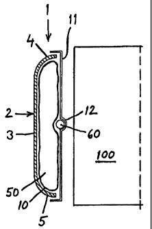
It will be apparent from Figs. 1 and 2 that the inventive,
destructive device 1 includes a channel 2 which, when in use,
faces towards the object 100 which the device is intended to
destroy in the event of unlawful manipulation. The channel 2
will preferably have a generally U-shaped cross-section,


CA 02259627 1999-O1-06
WO 98/01646 PCT/SE97/01237
3
including a bottom 3, two side-parts 4,5 and two end-walls
6,7. The channel 2 may be made of fibreglass reinforced
plastic or of aluminium, for instance.
Disposed within the channel 2 is a casing which contains a
s destructive agent 50 and which has the form of an end-sealed
hose 10. The hose 10 may be comprised of plastic foil and the
destructive agent may be a single-component liquid or a dye
of pronounced colour. The hose 10 filled with said
destructive agent is held in position by a grid or grating
11, which is either glued or screwed firmly to the channel 2,
for instance. Disposed between the hose 10 and the grating 11
is a string of explosive agent 60. The string of explosive
agent 60 is accommodated in an outwardly bulged part 12 of
the grating 11. The length and breadth dimensions of the
casing 10 coincide generally with the inner dimensions of the
channel 2, so as to enable the channel 2 to be filled
effectively. The grating 11 will conveniently cover the whole
of the channel 2, and the string of explosive agent 60 will
conveniently extend along the full length of said channel 2.
The explosive agent 60 may have the form of an elongated,
optionally plastic-encapsulated, pentyl fuse, although other
explosive agents are, of course, conceivable.
When wishing to use a two-component destructive agent, the
end-sealed tube 10 is divided into two parts, and so on. The
hose 10 may, at times, be omitted, when electing to provide
the channel 2 with a thin cover or lid, fox instance a foil
' 30 lid, so as to enclose the destructive agent in the channel 2.


CA 02259627 1999-O1-06
WO 98/01646 PCT/SE97101237
4
Figs. 3 and 4 illustrate an alternative embodiment of a
destructive device 1', in which two channels 2' are
juxtaposed and covered with a common grating 11'. Each of the
channels 2' contains a respective hose 10' filled with
destructive agent. A string 60 of explosive agent is disposed
between the hoses 10' and the common grating 11', as evident
from Figs. 3 and 4. The channels 2' have a generally U-shaped
cross-section and are relatively deep. Each of the channels
2' has a bottom 3', two side-parts 4',5' and two end-walls
6',7'.
The function and use of the inventive destructive device will
now be described in more detail, with a starting point from
the stage in which the destructive device 1 is placed in an
alarm-protected security container and the explosive agent 60
is connected to the alarm device mounted in the container.
The length of the destructive device 1 will preferably be the
maximum length permitted by the security container, and the
destructive device will be placed as close to the objects 100
as is possible to ensure necessary destruction of the
objects, wherewith the channel opening faces towards the
objects 100, which may comprise stacks or bundles of sealed
plastic envelopes containing banknotes.
The following events take place when the destructive device 1
is activated/triggered by the alarm device.
The explosive agent 60 acts in two ways. The explosive agent
60 acts directly on the obj ects 100 and will open any seals
present and physically deform, e.g., banknotes or documents.
The explosive agent 60 punctures the hose or casing 10 of the
destructive agent 50 and propels the agent into contact with


CA 02259627 1999-O1-06
WO 98/01646 PCT/SE97/01237
the objects 100. The cross-sectional shape of the channel 2
contributes towards effectively guiding the destructive agent
50 towards the objects 100.
5 The embodiment illustrated in Figs. 3 and 4 also functions in
the aforedescribed manner and is used in the same way.
The components of a multi-component destructive agent will be
mixed very effectively by the explosive force generated,
prior to said components reaching the objects 100.
The configuration of the channel 2 is very significant to the
distribution of the destructive agent.
Thus, the inventive channel presents an opening which
functions to control distribution of the destructive agent.
The width of the channel opening and the configuration of the
channel, and the position of the explosive agent relative to
said channel, all have an effect on the pattern of
distribution of the destructive agent.
In one advantageous embodiment of the invention, the cross-
sectional shape of the channel will correspond to that of a
conventional vehicle headlamp, such that the channel will, in
principle, function analogously with a headlamp reflector. In
this respect, the explosive agent may be placed in what can
be called the focal point of the channel, therewith achieving
extraordinarily effective spreading of the destructive agent
through the medium of said channel.


CA 02259627 1999-O1-06
WO 98/01646 PCT/SE97101237
6
It will be understood that the structural components of the
inventive device 1 can be modified and varied in several
respects.
For instance, the hose or casing 10 may be divided into a
plurality of sub-casings along the channel 2.
The grating 11 may be replaced with plastic or metal foil for
instance, in which case the string of explosive agent may be
glued to the foil. If desired, the aforesaid foil can be used
to encapsulate the destructive agent in the channel.
It will be observed that the placement of the string of
explosive agent between the channel filling material, e.g.
encapsulated filling material (destructive agent) and the
object 100 enables the object/articles 100 to be burst apart
prior to expulsion of the channel or bowl of said reflector-
like construction.
It will therefore be understood that the invention is not
restricted to the illustrated and described embodiment
thereof and that modifications can be made within the scope
of the following Claims.

Dessin représentatif
Une figure unique qui représente un dessin illustrant l'invention.
États administratifs

Pour une meilleure compréhension de l'état de la demande ou brevet qui figure sur cette page, la rubrique Mise en garde , et les descriptions de Brevet , États administratifs , Taxes périodiques et Historique des paiements devraient être consultées.

États administratifs

Titre Date
Date de délivrance prévu 2005-09-27
(86) Date de dépôt PCT 1997-07-06
(87) Date de publication PCT 1998-01-15
(85) Entrée nationale 1999-01-06
Requête d'examen 2002-07-03
(45) Délivré 2005-09-27
Réputé périmé 2016-07-06

Historique d'abandonnement

Il n'y a pas d'historique d'abandonnement

Historique des paiements

Type de taxes Anniversaire Échéance Montant payé Date payée
Le dépôt d'une demande de brevet 300,00 $ 1999-01-05
Taxe de maintien en état - Demande - nouvelle loi 2 1999-07-06 100,00 $ 1999-07-06
Enregistrement de documents 100,00 $ 2000-01-06
Taxe de maintien en état - Demande - nouvelle loi 3 2000-07-06 100,00 $ 2000-06-29
Taxe de maintien en état - Demande - nouvelle loi 4 2001-07-06 100,00 $ 2001-07-05
Taxe de maintien en état - Demande - nouvelle loi 5 2002-07-08 150,00 $ 2002-07-02
Requête d'examen 400,00 $ 2002-07-03
Taxe de maintien en état - Demande - nouvelle loi 6 2003-07-07 150,00 $ 2003-06-30
Taxe de maintien en état - Demande - nouvelle loi 7 2004-07-06 200,00 $ 2004-06-28
Taxe de maintien en état - Demande - nouvelle loi 8 2005-07-06 200,00 $ 2005-07-04
Taxe finale 300,00 $ 2005-07-05
Taxe de maintien en état - brevet - nouvelle loi 9 2006-07-06 200,00 $ 2006-06-21
Taxe de maintien en état - brevet - nouvelle loi 10 2007-07-06 250,00 $ 2007-06-22
Taxe de maintien en état - brevet - nouvelle loi 11 2008-07-07 250,00 $ 2008-06-10
Taxe de maintien en état - brevet - nouvelle loi 12 2009-07-06 250,00 $ 2009-06-10
Taxe de maintien en état - brevet - nouvelle loi 13 2010-07-06 250,00 $ 2010-06-07
Taxe de maintien en état - brevet - nouvelle loi 14 2011-07-06 250,00 $ 2011-06-16
Taxe de maintien en état - brevet - nouvelle loi 15 2012-07-06 450,00 $ 2012-07-05
Taxe de maintien en état - brevet - nouvelle loi 16 2013-07-08 450,00 $ 2013-06-13
Taxe de maintien en état - brevet - nouvelle loi 17 2014-07-07 450,00 $ 2014-06-12
Titulaires au dossier

Les titulaires actuels et antérieures au dossier sont affichés en ordre alphabétique.

Titulaires actuels au dossier
SQS SECURITY QUBE SYSTEM AB
Titulaires antérieures au dossier
FRISTROM, OLA
LINDSKOG, KJELL
Les propriétaires antérieurs qui ne figurent pas dans la liste des « Propriétaires au dossier » apparaîtront dans d'autres documents au dossier.
Documents

Pour visionner les fichiers sélectionnés, entrer le code reCAPTCHA :


Pour visualiser une image, cliquer sur un lien dans la colonne description du document. Pour télécharger l'image (les images), cliquer l'une ou plusieurs cases à cocher dans la première colonne et ensuite cliquer sur le bouton "Télécharger sélection en format PDF (archive Zip)" ou le bouton "Télécharger sélection (en un fichier PDF fusionné)".

Liste des documents de brevet publiés et non publiés sur la BDBC .

Si vous avez des difficultés à accéder au contenu, veuillez communiquer avec le Centre de services à la clientèle au 1-866-997-1936, ou envoyer un courriel au Centre de service à la clientèle de l'OPIC.


Description du
Document 
Date
(yyyy-mm-dd) 
Nombre de pages   Taille de l'image (Ko) 
Abrégé 1999-01-06 1 54
Dessins représentatifs 1999-03-24 1 4
Description 2004-09-03 6 233
Page couverture 1999-03-24 1 46
Description 1999-01-06 6 235
Revendications 1999-01-06 2 71
Dessins 1999-01-06 2 38
Dessins représentatifs 2005-08-30 1 5
Page couverture 2005-08-30 1 38
Correspondance 1999-03-02 1 31
PCT 1999-01-06 11 420
Cession 1999-01-06 2 107
Cession 2000-01-06 4 160
Poursuite-Amendment 2002-07-03 1 44
Taxes 2003-06-30 1 31
Poursuite-Amendment 2004-09-03 3 78
Taxes 2002-07-02 1 35
Taxes 2001-07-05 1 31
Taxes 1999-07-06 1 53
Taxes 2000-06-29 1 50
Taxes 2004-06-28 1 34
Poursuite-Amendment 2004-08-26 1 30
Correspondance 2005-07-05 1 24
Taxes 2005-07-04 1 28