Note : Les descriptions sont présentées dans la langue officielle dans laquelle elles ont été soumises.
CA 02267053 1999-03-26
IMPROVEMENTS IN OR RELATING TO TUBE COUPLINGS
This invention relates to tube couplings.
My "Speedfit" tube connector (UK Patent No.
1520742 and others) has a coupling body with a
throughway open at one end and a tapered cam surface
in the open end to receive a collet for locking a tube
in the coupling. The collet is compressed against the
tube by a slight withdraw of the tube and collet from
the coupling body which locks the tube in the coupling
body. The collet can be depressed into the body to
release the tube.
My "SuperSeal" design (UK Patent No. 2167147)
has a separate sleeve screwed into the open end of the
coupling body in which the tapered cam is formed. By
screwing the sleeve into the coupling body the
gripping action of the collet on the tube is
increased. Also the collet becomes locked up in the
coupling body and cannot be depressed to release the
tube.
An object of the present invention is to provide
a tube coupling which can readily be adjusted manually
between one state in which a tube can be locked in and
released from the coupling body and a second state in
which a tube is locked first and cannot be released.
The invention provides a tube coupling comprising
a coupling body having a throughway open at one end to
receive an end portion of a tube and having an
internal cam surface tapering towards the open end in
which a collet is located for locking the tube in the
coupling body by engagement with the tapered cam
CA 02267053 1999-03-26
-2-
surface, and having stop means to limit entry of the
collet into the throughway, the coupling body having a
main body the throughway of which receives the end of
a tube and contains said stop means to limit insertion
of the collet and an end cap in screwthreaded
engagement with the main body containing said open end
to the throughway and the tapered cam surface, and
indexing means between the end cap and main body to
define different positions of rotational adjustment in
the first of which a tube can be inserted and, by
depressing the collet into the coupling body, released
from the coupling body and in the second of which the
collet is engaged with the stop means to prevent the
collet being depressed into the coupling body to
release the tube.
Preferably the end cap has an internally threaded
sleeve portion encircling and in screwthreaded
engagement with an external thread on the main body.
In the latter case said indexing means may be
provided between the mouth of the sleeve and a portion
of the main body beyond said threaded portion.
More specifically the indexing means may comprise
a radially inwardly directed projection at the mouth
of the sleeve and a plurality of cam means disposed
around the main body beyond the screwthreaded to
define said first and second positions of rotational
adjustment of the cap with respect to the sleeve.
In one particular arrangement according to the
invention the first cam means on the main body may
have an inclined cam face engaged by the projection on
the sleeve to provide an increasing resistance to
relative rotation when the projection encounters the
CA 02267053 1999-03-26
- 3 -
cam in screwing the body parts together and may have a
radial face beyond the inclined face with which the
projection is engageable to resist unscrewing of the
cap from the main body.
Furthermore a second cam means may be located on
said main body adjacent the first cam means to provide
a recess to receive said projection on the sleeve to
define said one position of rotation of adjustment of
the body parts.
Preferably the second cam means has an inclined
face opposite the first cam means to lift the
projection on the sleeve part over the second cam
means as the cap is screwed further onto the main body
together towards said second position of the cap/main
body.
In addition third cam means may be provided on
the main body having an inclined face on the side
adjacent the first step means to provide a resistance
for the projection to define the said second position
relative rotation of the body parts.
The following is a description of some specific
embodiments of the invention, reference being made to
the accompanying drawings, in which:
Figure 1 is a cross-sectional view of a tube
coupling in accordance with the invention including a
tube inserted in the coupling;
Figure 2 is a sectional view through the coupling
of Figure 1 along the line II-II;
CA 02267053 1999-03-26
- 4 -
Figure 3 is a perspective view of the two parts
of the coupling body of the coupling of Figure 1; and
Figures 4 and 5 are similar views to Figures 3
and 1 showing the coupling in a second locking
condition;
Figures 6 to 10 are similar views of Figures 1 to
showing a first modified arrangement;
Figure 11 shows a second modified arrangement;
Figures 12 and 13, 14 and 15 show further
modified arrangements.
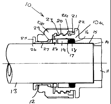
Referring firstly to Figure 1 of the drawings,
there is shown a tube coupling body indicated
generally by reference numeral 10 having a throughway
11 open at one end 12 to receive an end portion of a
tube 13. The coupling body comprises a main body 10a
and a cap lOb screwed onto the main body as described
below.
At a location spaced from the open end, the
throughway in the main body has a first increase in
diameter at a step 14 to provide an enlarged bore 15
in which the end of the tube 13 is a close sliding fit
with the end of the tubing engaging the step 14. The
throughway has a further increase in diameter at a
step 16 to form an enlarged bore 17 in which an 'O'
ring seal 18 is located against the step followed by a
spacer washer or compression ring 19.
The main body 10a of the coupling has an external
screw-threaded section 20 extending from the end of
CA 02267053 1999-03-26
- 5 -
the body part followed by a cam section indicated at
21 followed in turn by an encircling radial flange 22.
The cap lOb of the coupling body encircles the main
body and has an internal screw-threaded section 23
which mates with the screw-thread 20 on the main body.
The open end of the cap has a cam section 24 which
cooperates with the cam section 21 on the main body as
described later.
A collet indicated at 25 is mounted in the open
end of the coupling body comprising an annular member
26 and resilient arms 27 projecting from the annular
member into the throughway of the coupling body and
terminating in heads 28. The heads of the collet
engage in a tapered cam surface 29 converging towards
the end of the coupling body to be compressed against
the tube 13 by engagement of the heads with the cam
surface to lock the tube in the coupling body.
In the position shown in Figure 1, the cap 10a is
partially screwed onto the main body lOb and there is
a gap between the heads 28 of the collet and the
spacer washer 19 in the main body of the coupling
which allows the collet to be depressed into the
coupling body for release of the tube.
Referring now to Figure 2 of the drawings, the
cam section 21 of the main body between the thread 20
and the flange 22 is formed with first and second cams
and 312 located close together with a gap 32
30 between the cams. A further, third cam 33 is position
at 90° around the main body from the first and second
cams. The cams are engaged by an abutment 34 on the
inside of the enlarged end of the cap to define two
different rotational positions of the cap with respect
to the main body.
CA 02267053 1999-03-26
- 6 -
The cam 30 has a shallow incline 40 with which
the projection 34 is engageable as the cap is screwed
onto the main body. On the other side of the cam
there is a radial face 41 which forms an end stop
engageable with the projection 34 to resist reverse
movement of the cap. If the cap is forced and the
abutment 34 is damaged, that will be evident and
indicate misuse of the fitting.
Spaced opposite the face 41 of the cam 30 is the
second cam 31 which has an inclined face 42 adjacent
face 41 over which projection 34 can ride when the cap
is rotated further from said first position.
The cam 33 has angled ramps 43 and 44 on either
side thereof. As the cap is rotated towards a quarter
of a turn from the first position, the projection 34
engages the first ramp 43 which provides a resistance
to further movement as the projection rides up over
the cam. When the projection rides just over the peak
of the cam, the end of the cap engages the flange 22
as shown in Figure 4. In this position the collet is
drawn into the mouth of the main body of the coupling
to close up the gap between the collet arms and spacer
washer and to firmly clamp the arms of the collet
against the tube 13. In this position the collet
cannot be depressed into the coupling body to release
the tube as will be apparent from Figure 4.
When it is required to release the tube from the
coupling body, the cap is rotated back through a
quarter turn until the projection on the cap engages
between the first and second cams on the main body and
then the collet can be depressed into the coupling
body to release the tube.
CA 02267053 1999-03-26
The function of the cams will best be appreciated
from the following description, of events from
assembling the cap onto the body to releasing the cap
from the "SuperSeal" position.
The assembly operator assembles the cap onto the
body. The clockwise face of cam 31 offers little
resistance and the operator stops rotating the cap
once the clockwise face of cam 32 provides resistance.
The cap is now in the "Speedfit" condition, and
will remain here until the customer/end user wants to
change this.
The counter-clockwise face of the cam 30
precludes easy removal of the cap from the body. In
fact this face will be damaged if the cap is removed
thereby providing evidence of tampering.
If the user decides to adjust the fitting he/she
turns the cap past the nominal resistance of the
clockwise face of cam 31 and continues to rotate the
cap through a quarter turn past the slight
interference of the clockwise face of cam 33.
The cap has now compressed the collet, spacer
washer and 'O' ring together - thereby creating extra
grip and sealing as a "SuperSeal" connection. In
addition, any free play in the tube connection is
removed and the collet cannot be released
accidentally.
To release the fitting, the user must first turn
the cap counter-clockwise past cam 33 and the slight
interference afforded by the counter-clockwise face of
' CA 02267053 1999-06-24
_ g _
cam 31, and hence back to the "Speedfit" position.
The tube can now be removed by releasing the collet in
the usual way,provided by the "Speedfit" coupling.
Referring now to a first modified arrangement
shown in Figures 6 to 10, the first cam 30 on the main
body is replaced by an obliquely angled flexible leg
50 performing the same function as the solid cam 30.
The solid cam 31 and 33 may also be replaced by
obliquely angled flexible legs. The arrangement is
otherwise the same as that of Figures 1 to 5 and
operates in the same way.
The arrangement shown in Figure 11 is a further
modification in which the positions of the cams on the
body and cap are reversed. On the tube coupling body,
a single obliquely angled leg 51 is formed which
could, equally, be a cam of the form 24 provided on
the cap of the arrangements of Figures 1 to 5. The
cap is formed with a pair of closely spaced cams 52,
53 equivalent to cams 30 and 31 of the arrangement of
Figures 1 to 5 and a further circumferentially spaced
cam 54 equivalent to cam 33 on the body of arrangement
Figures 1 to 5. The arrangement of cams on the cap
and resilient leg on the coupling body will define
first and second positions of rotation of the cap with
respect to the coupling body as previously described.
Figures 12 and 13 show a further arrangement in
which the cams 30, 31 and 33 (not shown) on the body
are engaged by an axially extending flexible leg 55 on
the cap to define first and second positions of
rotation of the cap on the coupling body as before.
Figure 14 shows a further variant in which the
CA 02267053 1999-03-26
_ g _
coupling body is formed with a flange 60 having raised
cams 61 (only one of which can be seen) having a
shallow angle ramp 62 at one end and a perpendicular
face 63 at the other end. A resilient leg 64 on the
cap is engageable with the cams riding up over the
ramp and cam with clockwise rotation of the cap and
dropping down to the flange 60 beyond face 63 to
resist return movement. A similar cam is provided at
a spaced location around the flange to provide a
second position in which the cap is located with
respect to the coupling body.
Figure 15 shows yet a further arrangement in
which the cap has windows 70 (only one of which can be
seen) spaced around the cap and with which an
outwardly angled flexible leg 71 on the coupling body
is engageable to define the two spaced positions of
rotation of the cap with respect to the body.
25