Note : Les descriptions sont présentées dans la langue officielle dans laquelle elles ont été soumises.
~. ~,...~....~,.,a..,~ ~.... ~ . , ,
CA 02267227 2005-02-04
1
MBTHODI AND APPARATUS FOR MANUFACTURING OF A BRUSH RING
FIELD OF THE INVENTION
The invention relates to a method for manufacturing
of a brush ring, whereby the brush ring is intended to be
used particularly with several corresponding brush rings
as a brush, that rotates around a longitudinal axis, in a
brushing machine. The brush ring consists of a brush part
and a ring shaped frame part. The frame part connects the
radially directed bristles forming the brush part. The
frame and the brush parts are formed as a single member
uniformly from plastic based material. In the frame part
there has been arranged at least holding means to prevent
the brush ring from twisting, when the brush ring has
been assembled in place to the brush frame of the
brushing machine with the other brush rings placed one
after another in the longitudinal direction. The brush
ring is manufactured from an essentially elongated brush
preform, in which the bristles are connected to each
other by melting bristles together at one end to form a
melted edge. On the melted edge existing on top of the
brush preform, that moves along in an essentially upright
position, plastic paste is fed in. The plastic paste is
in an essentially solid state, to enable the brush ring
to be worked to its final shape by means of a press mold
assembly by forming the frame part and preferably the
holding means from the plastic paste.
BACKGROUND OF THE INVENTION
The type of brush rings described above are used to
form brushes in different kinds of sweeping trucks and
brushing machines. The brush rings being used today
usually comprise a ring shaped frame part. In other
words, tl~e frame part has been formed to a
CA 02267227 2005-02-04
circumferential shape when viewed from the side. The ring
shaped frame part is usually made of thin sheet iron, the
thickness of which is, for example, about 1 mm. The
bristles have been attached to this kind of frame part,
for example, by means of a suitable solidifying
attachment mass. This type of brush ring is usually
planar.
This type of brush ring, that is partly made of
metal, tends to break particularly because of cold, which
causes stiffening of the brushes. On such an occasion,
the frame sheet iron supporting the brush part of the
brush ring opens in certain places, in which case bigger
or smaller units of brush parts are released from the
brush ring. In addition to the foregoing problem, it is
practically impossible to re-use brush rings with metal
frames and plastic brushes, because removing the frame
sheet iron from the brushes is not economically justified
in practice. That is why this type of brush ring is
removed as a whole to the dumping area. That is naturally
a significant waste problem. Furthermore, when the type
of brush rings described above are being used, very
strongly built supporting structures must be used, also,
such as space rings made of metal, fastening rings etc.,
which is why a brush formed of this kind of brush rings
becomes disproportionately expensive.
On the other hand from Finnish Patent No. 87977, a
brush element is previously known, that is entirely made
of plastic based material. When applying the method
according to the afore-mentioned patent, plastic paste
existing essentially in a solid shape is fed onto the
melted edge existing at the top edge of the brush
preform, that moves along in an essentially upright
position, to work the brush ring to its final shape by
CA 02267227 2005-02-04
3
means of a press mold assembly by forming the frame part
and preferably the holding means from the plastic paste.
However, arrangements explained in Finnish Patent No.
87977 in particular for feeding the plastic paste on top
of the melted edge of the brush preform are insufficient
when being carried out in practice. This leads to the
plastic paste becoming unevenly distributed on the brush
preform. This leads furthermore to the result that, when
pressing the brush preform to bring out a final brush
ring, the final brush ring is not adequately as
homogeneous. This results in many significant
disadvantages in practice, when the brush ring is being
used in a brushing machine, wherein, for example,
vibration is caused due to unbalance. Furthermore, due to
the above-noted extra wearing of the brushing machine,
discomfort in the use of the machine is caused as well.
Furthermore, the brush elements being manufactured by the
method described in the patent above are planar. Thus,
due to wearing of the brushes, the brushing of the brush
formed of the brush rings becomes discontinuous in the
longitudinal direction of the brush, particularly in the
jointing points of the brush rings. Therefore, the brush
is not able to fulfill, to a satisfactory extent,
conventional demands that are requested in certain
purposes, because material to be brushed may go through
the brush without touching the bristles, in which case
the brush must be dismantled and the brush rings
replaced.
SUMMARY OF THE INVENTION
It is the aim of the method for manufacturing of a
brush ring according to the present invention to achieve
a decisive improvement in the problems presented above
and, thus, to essentially raise the level of knowledge in
~. ,....~._..w~..,....p-.~ ~yM.w.ypf,~.e~~~.,~~~..... i i ~ , i
CA 02267227 2005-02-04
4
the field. To achieve this aim the method according to
the present invention is primarily characterized in that
the plastic paste is fed out formed into a ready finished
shape, such as through a U-shaped extrusion groove or the
like, onto the brush preform, preferably on top of a
melted edge of the brush preform, that is being
simultaneously preheated.
Among the most important advantages of the method
are simplicity and reliability. Thanks to the invention,
it is possible to produce brush rings, the manufacturing
costs of which are significantly more profitable and that
are more homogeneous than present brush rings. In
particular the forming of the plastic paste into a
desired shape in advance improves significantly
homogeneity of the brush rings, because the plastic paste
forming the frame part is prevented from being unevenly
distributed. Thanks to the invention, the brush rings
manufactured by this method are both very user-friendly
and durable, particularly due to their homogeneity. When
exploiting advantageously preheating of the brush
preform, the method according to the invention
furthermore assures that the contact between the solid
melting paste connecting the brush preform and brush ring
to each other is achieved reliably and effectively when
the plastic paste is extruded on the brush preform. The
preheating described above also causes roughness of the
melted edge of the brush preform to be balanced by
influence of heating, which furthermore enables a contact
as even as possible between the melted edge and the
plastic paste.
According to an aspect of the present invention,
there is provided a method for manufacturing a brush ring
that is to be used with a plurality of similar brush
._..~_~,.~..,.~,._,"."~"",~~,.. ~ ,
CA 02267227 2005-02-04
rings as a brush that rotates around a longitudinal axis
in a brushing machine, the brush ring comprising a brush
part formed of radially directed bristles and a ring
shaped frame part that connects the bristles, the brush
part and the frame part being formed as a single member
and including holding means for preventing the brush ring
from twisting when the plurality of brush rings have been
assembled one after another in a longitudinal direction
on a brush frame of a brushing machine, the method
comprising: providing an essentially elongated brush
preform in which the bristles are connected to each other
at one end; feeding plastic paste in an essentially solid
state onto said one end of the bristles at a top edge of
the preform, the plastic paste being fed in a finished
shape; and working the brush ring to a final shape
utilizing a press mold assembly to form at least the
frame part from the plastic paste.
Advantageous embodiments of the method according to
the invention are described below.
The invention relates to an apparatus functioning
according to the principle of the method as well, that is
being described in a greater detail below.
The most important advantages of the apparatus
according to the invention include simplicity and
reliability of its construction and use. By very simple
arrangements, for example, when advantageously preheating
the brush preform during extrusion, it is possible to
achieve a uniform and continuous contact between the
melted edge of the brush preform and the plastic paste to
be extruded on it. The brush rings manufactured by the
apparatus are particularly homogeneous, due to the
extrusion groove existing in the extrusion device
belonging to the apparatus. The shape of the groove
CA 02267227 2005-02-04
6
corresponds to the shape of the brush preform and places
the plastic paste in a ready formed shape on the brush
preform, thereby preventing it from being unevenly
distributed. The brush rings manufactured by the
apparatus according to the invention hold together
particularly well due to contact between the plastic
paste forming the frame part and the brush preform
forming the brush part being sufficiently efficient due
to preheating. Accordingly, the brush rings manufactured
by the apparatus, in addition to being homogeneous are
also durable due to a strong structure. It is
advantageous to use the apparatus according to the
invention particularly in connection with a brush ring,
in which the touching point of the outer radial edge of
the brush part of the brush ring has an effect within the
whole width of the brush ring, to achieve an essentially
unbroken brush touch in the longitudinal direction of the
brushing machine to the object being brushed continuously
regardless of the length of the bristles, when the brush
rings forming the brush keep rotating around the
longitudinal axis. The brushing result of this type of
zip-zap brush ring remains optimal with a respect to
brushing effect despite wearing of the bristles
significantly longer than with currently utilized planar
brush rings. That means, in principle, until the bristles
wear out.
According to an aspect of the present invention,
there is provided an apparatus for manufacturing a brush
ring that is to be used with a plurality of similar brush
rings as a brush that rotates around a longitudinal axis
in a brushing machine, the brush ring comprising a brush
part formed of radially directed bristles and a ring
shaped frame part that connects the bristles, the brush
CA 02267227 2005-02-04
part and the frame part being formed as a single member
and including holding means for preventing the brush ring
from twisting when the plurality of brush rings have been
assembled one after another in a longitudinal direction
on a brush frame of a brushing machine, wherein the brush
ring is manufactured from an essentially elongated brush
preform in which the bristles are connected to each other
at one end, the apparatus comprising: an extrusion device
including an extrusion frame for feeding plastic paste in
an essentially solid state on said one end of the
bristles, wherein the plastic paste is arranged to be fed
in a ready finished shape; and a press mold assembly for
working the brush ring to a final shape by forming at
least the frame part from the plastic paste.
Advantageous embodiments of the apparatus according
to the invention are described below.
BRIEF DESCRIPTION OF THE DRAWINGS
In the following description, the invention is
illustrated in greater detail with reference to the
appended drawings, in which
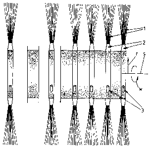
FIGS. 1a and lb show sectional side views of a brush
formed of conventional brush rings as after brief use (a)
and after heavy use (b) ,
FIG. 2 shows a perspective view of an advantageous
brush ring according to the present invention,
FIG. 3a shows a front view of manufacturing of the
brush ring shown in FIG. 2,
FIG. 3b shows a cross-sectional view of a portion of
the brush ring, as seen along lines 3b--3b of FIG. 3a;
FIGS. 4a and 4b show, respectively, a front view and
a side view of an extrusion frame of an apparatus
applying the method according to the invention, and
CA 02267227 2005-02-04
8
FIGS. 5a and 5b show advantageous counterpart
surface arrangements of an apparatus applying the method
according to the invention.
DETAILED DESCRIPTION OF TI3E INVENTION
The invention relates to a method for manufacturing
of a brush ring. The brush ring is intended to be used
particularly with several corresponding brush rings as a
brush, that rotates in a direction w around a
longitudinal axis s, in a brushing machine. The brush
ring consists of a brush part 1 and a ring shaped frame
part 2, that connects the bristles 1 a radially directed
in a direction r and forming the brush part 1. Parts 1, 2
are formed, preferably, as a single member uniformly from
plastic based material. In the frame part 2 there has
been arranged at least holding means 3 to prevent the
brush ring from twisting, when the parts have been
assembled in place to the brush frame of the brushing
machine.
As shown in FIGS. 4a and 4b, the brush ring is
manufactured from an essentially elongated brush preform
1'. The bristles la are connected to each other by
melting together ends of the bristles la to form a melted
edge 1's. Upon the melted edge 1's existing on top of the
brush preform 1', which moves along in an essentially
upright position, plastic paste 2' in an essentially
solid state is advanced. The brush ring is worked to its
final shape by means of a press mold assembly X by
forming the frame part 2 and preferably the holding means
3 from the plastic paste 2'. The plastic paste 2' is
advanced formed into a ready finished shape, such as
through a U-shaped extrusion groove U or the like, on top
of the melted edge 1's of the brush preform 1'. The brush
preform 1' is advantageously preheated.
CA 02267227 2005-02-04
9
As a particularly advantageous embodiment, the
extrusion device 4 that feeds solid plastic paste 2',
such as an extruder or the like, comprises a heated and
an essentially elongated extrusion frame 4a. Inside of
frame 4a the brush preform 1' is advanced through a
passage duct 4a~ existing therewith, particularly for
preheating of the melted edge 1's of the brush preform 1'
before extruding the plastic paste 2' on it.
The principle described above may be observed
particularly from FIGS. 4a and 4b, which show an
extrusion frame of an extrusion device applying the
method according to the invention as a front view and a
side view. Furthermore in the advantageous brush rings
shown in FIGS. 2 and 3a, principles of the applicants
previous Finnish patent application FI 963433,
"Harjakiekko" have been adapted.
As shown in FIG. 2, the frame part 2 of the brush
ring has an essentially constant cross section. The frame
part 2 undulates in a wave-type form having at least a
lower level o and an upper level x. The upper level x is
displaced from the lower level o in a direction s. A
three-dimensional press mold assembly X, shown in FIGS.
5a and 5b, may be used to form the frame part 2 into the
described shape. The press mold assembly X has press
molds X1. In an advantageous embodiment, surfaces of the
press molds X1 that come into contact with the frame part
1 and brush part 2 during formation of the brush ring
have tour projections for forming portions of the ring on
the x level, to one side si of the lower level o, as
shown in FIG. 3b.
When comparing a known brush, as shown in FIGS. la
and lb, and its function with a brush formed of brush
rings according to the invention and its function, it may
CA 02267227 2005-02-04
1~
be observed that the brush ring according to the
invention may be used in principle as long as an adequate
brushing effect may still be obtained with the bristles.
When coupling known brush rings, space collars are always
needed in principle between the brush rings placed one
after another. This points out furthermore unsatisfactory
functioning of known planar brush rings in the respect
that, due to wearing of the bristles, with reference
particularly to FIG. 1b, the brushing surface presented
by the outer radial edge of the brush very quickly
becomes discontinuous. For example, the brush shown in
FIG. lb would not be useable any more for most usual
purposes. Similarly, the brush shown in FIG. la would
already be nearly unsatisfactory for certain especially
demanding purposes.
Furthermore as an advantageous embodiment of the
method, the entire brush ring, including the bristles la
forming the brush part 1 and the plastic paste 2' forming
the frame part, may be manufactured from recyclable and
preferably essentially the same manufacturing material,
such as polypropylene.
Furthermore as an advantageous embodiment, the width
of the plastic paste 2' extrusion is adjusted to
correspond essentially to the width of the brush preform
1' of each brush ring to be manufactured by using
extrusion frames 4a having, for example, interchangeable
extrusion grooves U and/or passage ducts 4a' with
different dimensions.
The apparatus for manufacturing the type of brush
rings described above comprises, thus, at least an
extrusion frame 4a to feed plastic paste 2', formed into
a ready finished shape, such as through a U-shaped
extrusion groove U or the like, on the brush preform 1',
CA 02267227 2005-02-04
11
that is preferably preheated. After extrusion, the brush
ring may be worked to its final shape between the press
mold assembly X to form both the frame part 2 and
advantageously the holding means 3 as well from the
plastic paste 2'.
As an advantageous embodiment the extrusion device 4
feeding solid plastic paste 2' comprises a heated and
particularly with reference to FIG. 4b, an essentially
elongated extrusion frame 4a, to guide the brush preform
1' inside the same through a passage duct 4a',
particularly for preheating the melted edge 1's of the
brush preform 1' before extruding the plastic paste 2' on
it. As an advantageous embodiment, the extrusion groove U
and/or the passage duct 4a' of the extrusion device 4 are
connected removably to the extrusion frame 4a, to adjust,
for example, the width of the extrusion and/or of the
passage duct to correspond essentially to the width of
the brush preform 1' of each brush ring to be
manufactured. Furthermore, with reference particularly to
FIG. 4a, the extrusion frame 4a has a passage duct 4a' at
its bottom, the width of which corresponds essentially to
the width of the brush preform 1', when viewed in a cross
section as shown in FIG. 4a. Furthermore, with reference
to FIG. 4b, at the extrusion end I of the extrusion frame
4a, the extrusion groove U existing therein surrounds the
passage duct 4a'.
Furthermore, as an advantageous embodiment, the
brush ring has been worked to its final shape by means of
the press mold assembly X, whereby the holding means 3
are formed simultaneously, when the frame part 2 is being
pressed to the press mold assembly X, by means of a
counterpart surface arrangement 6 existing in the press
mold assembly X, whereby the holding means 3 are formed
._n_~.."~..~.. , . , ,
CA 02267227 2005-02-04
12
by means of mat-erialwspreading from the frame part 2
thereto during pressing. The counterpart surface
arrangement 6 is a unit, that is connected removably to
the press mold assembly X, particularly for preparing
brush rings with differing holding means 3 by replacing
only the counterpart surface arrangement 6 and otherwise
using one and the same press mold assembly X.
Furthermore as an advantageous embodiment of the
invention, the counterpart surface arrangement is
intended particularly for manufacturing of a brush ring
that comprises an essentially circumferential frame part
2, when viewed from the side, in which case the holding
means 3 comprises at least one shoulder arrangement 3a
existing therewith and, whereby the brush part 1 and the
frame part 2 are entirely made of recyclable and
preferably essentially of the same manufacturing
material, such as polypropylene. With reference to the
embodiments shown particularly in FIGS. 3a, 5a and 5b,
the counterpart surface arrangement 6 has been attached
removably, preferably, to the lower press mold X1 of the
press mold assembly X, preferably by means of a quick
locking principle, such as by means of a form locking
joint, screw joint 5 and/or the like.
With reference particularly to the advantageous
embodiment shown in FIG. 3a, the counterpart surface
arrangement 6 is carried out by an interchangeable
counterpart piece 6a, that is placed essentially at the
point of the holding means 3 in the press mold X1.
Furthermore as an advantageous embodiment, the
counterpart surface arrangement 6 may be arranged, i.e.,
implemented, by one uniform interchangeable counterpart
surface existing in the press mold X1, that is, for
example, continuously pressed against the frame part 2 in
CA 02267227 2005-02-04
13
the radial direction. Such a uniform interchangeable
counterpart surface may be formed, as shown in FIG. 5a,
of a uniform circular ring 6a', and as shown in FIG. 5b
of, for example, an essentially uniform planar
interchangeable counterpart plate 6a". The essentially
uniform planar interchangeable counterpart plate 6a" may
be attached to a surface of the press mold. The surface
of the press mold may be essentially planar.
It is obvious, that the invention is not limited to
the embodiments presented or described above, but it can
be modified within the basic idea even to a great extent.
In this case, it is first of all possible to form the
type of brush rings described above of a frame part, that
is, for example, wider than described above and into
which there has been attached, for example, one single
spiral-shaped brush part that has been implemented by
means of a two or multiple ended threading. It is also
possible to exploit the principle described above on the
other hand by using a solution like the one shown in FIG.
2, in which the frame part comprises a structure, that
has, for example, knees extending sidewards instead of a
structure having a constant cross section. It is also
possible to equip the brush rings according to the
invention with auxiliary holding arrangements,
functioning, for example, on the male-female-principle
and that are placed at the axially directed side surfaces
of the frame parts in the brush ring, in which case
auxiliary counterpart surface arrangements for the above
are naturally needed. It is naturally possible to produce
a brush ring according to the invention from most
heterogeneous materials, by exploiting most heterogeneous
manufacturing methods. In the foregoing description, use
of polypropylene as the manufacturing material of the
CA 02267227 2005-02-04
14
brush rings has been represented as only--one example,
that is, however, a very suitable alternative in this
context.