Note : Les descriptions sont présentées dans la langue officielle dans laquelle elles ont été soumises.
CA 02267480 1999-03-29
(26076E.DOC Prt: 11.03.1999 VE)
- 1 -
AUTOMATIC ANALYZER
The present invention refers to an automatic analyzer for
the assay of liquid samples, said automatic analyzer
comprising a mixing chamber which is followed by an
analyzing block including an evaluating unit, said mixing
chamber comprising at least one inlet opening for air
respectively water and being connected to an outlet opening
for the analyzed liquid.
Automatic analyzers of the mentioned kind are known.
As an example of the prior art, Fig. 1 illustrates the block
diagram of an automatic analyzer 10 for the selective
determination of ions, e.g. Li+, K+, Na+, C1-, in liquid
samples of biological substances such as blood or urine. The
samples are placed on a sample platform 11 in separate
containers. By means of an automatic pipette arm 12, small
amounts of the samples are now serially supplied to a mixing
chamber 14. Chamber 14 essentially consists of an upwardly
open, cylindrical vessel having a continuously tapering
bottom. Inlet openings 15, 16 for air and water,
respectively, are laterally connected to the top of this
vessel, and two outlet openings 17, 20 are connected to its
bottom. The liquid samples delivered by the pipette needle
are homogenized by means of an air vortex generated by
opening 15, and supplied by outlet opening 20 and a
connecting duct 21 to the measuring channel of an analyzing
block 22, e.g. an electrode block. Second inlet opening 16
mainly serves for the supply of rinsing water and outlet
opening 17 for the extraction of the latter and of possible
excess liquid (waste).
CA 02267480 1999-03-29
= (26076E.DOC Prt: 11.03.1999 VE)
- 2 -
The measuring channel of analyzing block 22 is e.g. provided
with several ion-selective electrodes and a reference
electrode connected thereto which measure the ion
concentration e.g. of the above-mentioned ions and output
the measuring results by means of an electronic evaluating
system 24. Finally, the sample liquid is discharged into a
collector 25 for disposal.
The operation of automatic analyzers of the represented kind
should be as free of disturbances as possible. However,
since the analyzed liquids come from a large number of
sources, this aim can only be attained within certain
limits. In particular, frequent problems are caused by small
particles such as coaguli which may choke the analyzer,
thereby resulting in incorrect analyses or even rendering
the measurements impossible. In such cases, the critical
components must be disassembled and cleaned, thereby causing
complications and time losses.
Consequently, the aim of the invention is to provide an
improvement of the known automatic analyzers which allows to
prevent the described obstructions as largely as possible.
This aim is attained by an automatic analyzer wherein said
mixing chamber is disposed in a dedicated, exchangeable
unit, and wherein said outlet opening for the analyzed
liquid is associated with a particle collecting trap. The
dependent claims indicate developments and alternative
embodiments of the invention.
In particular, the advantages obtained with the automatic
analyzer of the invention consist in that the mixing chamber
is easily exchangeable, so that impairments of the operation
CA 02267480 1999-03-29
(26076E.DOC Prt: 11.03.1999 VE)
- 3 -
of the automatic analyzer by an obstruction of the mixing
chamber by a particle, e.g. a coagulum, are easily and
quickly eliminated. Furthermore, the mixing chamber design
of the invention allows quick and effective cleaning, so
that possible particles in its outlet channel are easily
removed.
The invention is described in more detail hereinafter with
reference to the figures, where
FIG. 1 shows a block diagram of an automatic analyzer of
the prior art as previously discussed above;
FIG. 2 shows a perspective view of a mixing chamber unit
and of the associated base unit;
FIG. 3 shows a cross-section of the mixing chamber unit;
and
FIG. 4 shows a cross-section of the mixing chamber unit
and of the base unit.
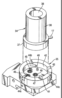
Fig. 2 shows a mixing chamber unit 34 and an associated base
unit 35 in a perspective view. Mixing chamber unit 34 is
provided with an essentially cylindrical outer wall 36 which
is seamlessly followed at the bottom by a base plate 37 of a
larger diameter. The first outlet opening 17 laterally
projects from plate 37 in the form of a connecting nipple
which allows the connection of a drain water tube. Mixing
chamber unit 34 is open at the top (sample opening 38) and
comprises a plane bottom. The latter communicates with
outlet opening 17, which is hidden in the illustration but
CA 02267480 1999-03-29
(26076E.DOC Prt: 11.03.1999 VE)
- 4 -
visible in FIG. 1. Furthermore, two risers lead up from the
bottom into wall 36 of mixing chamber 34 and communicate
with the inlet openings 15, 16 illustrated in FIG. 1.
The base unit 35 constitutes the counterpart of mixing
chamber unit 34 in automatic analyzer 10. Accordingly, base
unit 35 comprises a plane bottom 41 which is cylindrically
surrounded by a cylindrical guide 42 adapted to insertable
base plate 37. Cylindrical guide 42 is provided with an
incision 43 for the reception of outlet opening 17 and with
three locking slots 44a, 44b, 44c. Bottom 41 communicates
with connection 45 of the air riser, with connection 46 of
the water riser, and with connection 47 of the second outlet
opening 20 for the analyzed liquid. Further provided is a
pin 48 which cooperates with a non-represented blind bore of
base plate 37 in order to allow a correct angular guidance
of mixing chamber unit 34 while it is inserted into base
unit 35.
Connections 45, 46, 47 are provided with (preferably
exchangeable) sealing rings 49 (FIG. 4) which ensure a tight
connection with openings 15, 16 respectively 20. Mixing
chamber unit 34 is attached to base unit 35 by a non-
represented coupling ring which is slipped over mixing
chamber unit 34 from above and seizes the upper edge of base
plate 37, and which is secured by a clockwise rotation by
means of internal pins which engage in locking slots 44a,
44b, 44c.
FIG. 3 shows a central cross-section of mixing chamber unit
34 at a scale of approx. 2 : 1 with respect to its real
size. Upwardly open mixing chamber 14 is cylindrical in
shape while its wall surface is as smooth as possible and
CA 02267480 1999-03-29
('26076E.DOC Prt: 11.03.1999 VE)
- 5 -
e.g. conically tapered at the bottom. At the pointed end of
mixing chamber 14, the wall of the mixing chamber comprises
an outlet opening 18 which is followed by a vertical bore 19
whose diameter respectively clear width approximately
corresponds to that of connecting duct 21 and of the
measuring channel of analyzing block 22. This vertical bore
19 is horizontally connected to first outlet opening 17. At
the bottom, bore 19 is followed by second outlet opening 20
whose diameter abruptly decreases at transition 13, said
diameter being e.g. reduced to a third of the diameter of
bore 19. Practical values are e.g. 0.3 to 0.4 mm for outlet
opening 20 and 0.8 mm for bore 19. Restriction 13 serves as
a trap for particles which are capable of causing the
obstructions described in the introduction.
FIG. 4 shows another cross-section of mixing chamber unit 34
and of base unit 35 on a further enlarged scale. At the
location of restriction 13 between bore 19 and second outlet
opening 20, i.e. in the collecting trap, a particle 23 is
shown whose travel in the direction of connection 47 is
hindered. Particle 23 reduces or blocks the desired flow of
the analyzed measuring liquid toward analyzing block 22. The
occurrence of this condition is detected by a fluid sensor
50 at connection 47 which detects the absence of the
expected liquid. In this case, the automatic analyzer can be
stopped.
In order to eliminate such an obstruction, it may be
attempted to flush the blocking particle by the supply of
water from inlet opening 16 and its extraction by lateral
outlet opening 17. Alternatively, the concerned mixing
chamber unit 34 can be replaced in few operations by a spare
unit, thereby restoring the operativeness of automatic
CA 02267480 1999-03-29
(26076E.DOC Prt: 11.03.1999 VE)
- 6 -
analyzer 10. The concerned mixing chamber unit 34 is also
easily cleaned by flushing respectively blowing it through
from outlet opening 20 to mixing chamber 14, so that the
formerly concerned unit 34 is available as a new spare unit.
The described division of the automatic analyzer 10 into a
basic apparatus comprising base unit 35 and into an easily
exchangeable mixing chamber unit 34 comprising a particle
trap is simple in construction and allows to avoid prolonged
failures of analyzer 10. Fluid sensor 50 provides a safe
detection of a possibly required exchange and cleaning of
the mixing chamber unit. Those solid constituents of the
analyzed liquid which pass second outlet opening 20 do not
impair the measurements in analyzing block 22 and do not
constitute a risk of obstructions of the hitherto usual
kind. Standstill times of automatic analyzers 10 as well as
the required maintenance are thus substantially reduced.
A large number of alternatives are possible within the scope
of the invention, some of which are listed in particular
herebelow.
- The shape of the mixing chamber does not necessarily have
to be cylindrical. It may also be convex or have an oval
cross-section, for example. However, the container walls
should be smooth in order to avoid material deposits.
Furthermore, a tapered zone must be provided at the bottom
in order to ensure a perfect draining of the liquid.
- First outlet opening 17 for the drained liquid may be
directed downwards instead of sideways.
CA 02267480 1999-03-29
(26076E.DOC Prt: 11.03.1999 VE)
- / -
- The attachment of mixing chamber unit 34 in base unit 35
may be obtained by different means, e.g. by a lever closure.
- Instead of bore 19 and outlet opening 20 whose cross-
sections are both cylindrical, the particle trap may also be
formed by non-cylindrical cross-sections, e.g. by a trefoil
cross-section of outlet opening 20.
- The particle trap may be an integral part of mixing
chamber unit 34, as described above. It is also possible,
however, to obtain the reduction of the clear width of bore
19 by a separate part which is exchangeably disposed
transversally or longitudinally in said bore, e.g. a nozzle
screwed into bore 19.
The invention therefore refers to an automatic analyzer 10
for the assay of liquid samples, comprising at least a
vertically extending mixing chamber 14 having at least one
inlet opening 15, 16 for air and water, respectively, and an
outlet opening 20 for the analyzed liquid, as well as an
analyzing block 22 following mixing chamber 14 and including
an evaluating unit 24, wherein mixing chamber 14 is disposed
in a dedicated, exchangeable unit, and wherein outlet
opening 20 for the analyzed liquid is associated with a
collecting trap for particles 23.