Note : Les descriptions sont présentées dans la langue officielle dans laquelle elles ont été soumises.
CA 02267674 2008-11-06
-1-
Title: METHOD FOR COOLING AN ARC LAMP
FIELD OF THE INVENTION
This invention relates generally to arc lamps primarily but not
exclusively for use as projection lamps in motion picture projectors.
BACKGROUND OF THE INVENTION
Xenon arc lamps generate significant heat in operation and must
be cooled in order to achieve acceptable lamp life. In an air-cooled
projector,
the lamp is located in a lamphouse and sufficient air flow must be provided
within the lamphouse to remove heat generated by the arc lamp. An example
of a projector having an air cooled xenon arc lamp is disclosed in United
States Patent No. 5,587,750 (Gibbon, et al.). The patent does not provide
specific disdosure of how the lamp is cooled but Fig. 1 of the drawings does
show (at 46) a hose through which cooling air for the lamphouse (42) is
exhausted from the projector.
A xenon arc lamp typically has a glass envelope enclosing an
anode and a cathode between which the arc is struck. An atmosphere of inert
xenon gas under pressure is provided within the envelope. The anode and
cathode are located in a bulb in the glass envelope at opposite ends of
respective electrode assemblies. The electrode assemblies are housed within
coaxial cylindrical portions of the envelope that extend in opposite
directions
from the bulb. Accordingly, the lamp has a defined axis represented by the
anode and cathode assemblies. In some applications, the lamp is oriented
with its axis vertical (e.g. 15 ), usually with the anode uppermost. Xenon
arc lamps can, however, be run in a horizontal orientation also.
DESCRIPTION OF THE PRIOR ART
The patents literature contains numerous examples of
proposals for cooling lamps. A xenon arc lamp with improved reflector
cooling is disclosed in U.S. Patent No. 5,721,465 (Roberts). A searchlight
incorporating a xenon arc lamp is disclosed in U.S. Patent No. 5,369,557
CA 02267674 2008-11-06
-2-
(Ronney).
U.S. Patent No. 4,630,182 (Moroi et al.) discloses a prior proposal
for cooling short arc mercury lamps. Unlike xenon arc lamps, a short arc
mercury lamp does not have an anode and cathode, and the orientation of the
s lamp in operation is not critical.
Examples of other patents that disclose inventions relating to
the cooling of lamps are U.S. Patents Nos. 5,091,835 (Malek, et al.) and
5,458,505 (Prager).
SUMMARY OF THE INVENTION
The present inventors have recognized that, in an air-cooled arc
lamp, while sufficient air flow must be provided to remove heat generated by
the lamp, the nature of the air flow over the bulb of the lamp also is
important
and can affect the performance of the lamp. If the air flow is too great, gas
(xenon) turbulence can be created within the bulb itself, causing arc
instability. In the case of a projection lamp, this instability can be seen as
an
annoying flicker on the projection screen. It has been found that the air flow
can also contribute to arc instability and flicker if it is non-uniform over
the
surface of the lamp bulb.
Where the lamp is oriented vertically (usually anode upwards)
it has been found that the arc has a tendency to wander at high frequencies,
which is especially noticeable as flicker on the projection screen. For this
reason, it has been recognized as critical to precisely control the air flow
over
the lamp.
Accordingly, the present invention is aimed at addressing these
problems both as they relate to arc lamps for motion picture projectors, and
in
arc lamps generally.
In one aspect of the invention, there is provided a method of
cooling a D.C. lamp having coaxial anode and cathode end portions and a
glass envelope that includes a bulb between said end portions. The method
involves supporting the lamp in a collector within a lamphouse by means of a
support that includes a shroud for one end portion of the lamp so that said
one end portion and the bulb are within the collector and the lamp extends
through an annular opening in the collector with the other lamp end portion
CA 02267674 2008-11-06
-3-
outside the collector. The shroud provides an annular air space around the
end portion of the lamp, and has an inlet for cooling air and an annular air
outlet that is directed towards the bulb of the envelope. Cooling air is
caused
to flow through the shroud from the shroud inlet to the shroud outlet. Air
leaving the outlet flows over the bulb to said annular opening in the
collector
as an annular airstream, cooling the lamp.
The invention also provides a D.C. lamp assembly that includes
a lamp of the form referred to previously and a lamphouse including a light
collector and an opening through which light reflected from the lamp by the
collector leaves the lamphouse. The lamphouse has an inlet and an outlet for
cooling air, and a fan is provided for causing air flow between the inlet and
the outlet. The assembly includes lamp supports for the respective end
portions of the lamp said supports positioning the lamp with said bulb and
one of said lamp end portions within the collector and the other said end
portion of the lamp outside the collector, the bulb extending through an
annular opening in the collector. The lamp support for said one lamp end
portion includes a shroud for the relevant end portion of the lamp, that
provides an annular air space around that end portion of the lamp. The
shroud has an inlet for cooling air and an annular air outlet that is directed
towards the bulb of the lamp envelope. The cooling air inlet to the
lamphouse communicates with the air inlet to the shroud and the cooling air
outlet from the lamphouse is located remote from the shroud such that
cooling air entering the shroud in use flows as an annular airstream over the
bulb and through said annular opening in the collector for cooling the lamp.
As indicated previously, the invention is based on the
recognition that precise control of cooling air flow over the surface of the
lamp is critical to arc stability. The annular air gap between shroud and the
end portion of the lamp (usually the anode end) creates a "sheet" of laminar
air flow which tends to "adhere" to the surface of the bulb, thereby providing
precise cooling. In practice, it has been found that only one cooling fan is
necessary for a projection lamphouse and the that air flow can be precisely
controlled to provide adequate cooling while avoiding excessive air flow
(which could lead to unwanted arc movement).
CA 02267674 2008-11-06
- 3a -
Preferably, the shroud itself is carried by a support arm that
extends inwardly from a wall of the lamphouse. The arm is hollow and
CA 02267674 1999-03-31
-4-
communicates with the air inlet to the shroud at one end, and with the air
inlet to the lamphouse at its opposite end. The cooling air then flows
along the arm and into the shroud. The shroud preferably is positioned
asymmetrically with respect to the end of the lamp so that the gap between
the shroud and the lamp varies from a maximum adjacent the air inlet to
a minimum at the opposite side of the end of the lamp. This offset
addresses the tendency of air to move faster near the inlet. The wider gap
reduces the air speed while the narrower gap at the opposite side increases
the speed of the air. Overall, the result is a more uniform air flow around
the entire circumference of the lamp.
BRIEF DESCRIPTION OF DRAWINGS
In order that the invention may be more clearly understood,
reference will now be made to the accompanying drawings which
illustrate a particular preferred embodiment of the invention by way of
example, and in which:
Fig. 1 is a diagrammatic perspective view of a motion picture
projector having an arc lamp assembly of the form provided by the
invention;
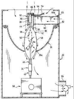
Fig. 2 is a vertical sectional view through the lamphouse of
the projector shown in Fig. 1;
Fig. 3 is an exploded perspective view of the anode end of the
lamp, support arm and shroud shown in Fig. 2; and,
Fig. 4 is an enlarged perspective view from the right in Fig. 3.
DESCRIPTION OF PREFERRED EMBODIMENT
Fig. 1 shows generally a motion picture projector of the form
disclosed in the '750 U.S. patent (Gibbon et al.) referred to previously.
Reference may be made to the disclosure of that patent for details of the
projector mechanism. For present purposes, it is sufficient to note that the
projector is of the so-called "rolling loop" type. Reference numeral 20
denotes a lamphouse that is located below a rotor 22 of the projector. Film
transported through the projector is indicated at 24 and passes around a
portion of the surface of the rotor 22 inwardly of a stator 26. A projection
CA 02267674 1999-03-31
-5-
lens assembly is indicated at 28. Light from the lamphouse 20 is directed
upwardly and reflected forwardly by a mirror 30, through the film 24 and
then through the projection lens 28. Reference numeral 32 denotes a
"spider" that rotationally supports the rotor 22 from above.
Lamphouse 20 is essentially a rectangular box or enclosure
within which is supported a projection lamp 34 and a light collector 36. As
best seen in Fig. 2, lamp 34 has an anode end portion 38 and a cathode end
portion 40 and the two portions are coaxial with one another. A quartz
glass envelope 42 encloses respective anode and cathode assemblies 44 and
46 and includes a bulb 48 between the ends. The bulb houses the actual
anode and cathode electrodes 50, 52 respectively between which the arc of
the lamp is struck. An inert gas (typically xenon) is maintained under
high pressure within the glass envelope and the anode and cathode
assemblies 44, 46 respectively are provided with pressure seals (not
shown). A power supply cable to the anode is denoted 54.
The lamp is of conventional construction.
The lamp 34 is held and positioned with respect to the
collector 36 by an anode support 56 and a cathode support 58.
The cathode support 58 is illustrated diagrammatically in Fig.
1 and is essentially conventional. The support provides for adjustability of
the cathode end of the lamp in so-called "X", "Y" and "Z" directions that
are mutually at right angles. In other words, the position of the lamp can
be adjusted by moving the cathode end up and down or laterally in two
directions at right angles to one another. As can be seen, the lamp 34 in
fact extends through an opening 36a at the bottom of the collector so that
the cathode end of the bulb is outside the collector. The cathode support 58
is adjusted so that the arc that is struck between the anode and cathode
electrodes 50, 52 is precisely positioned with respect to the focus of the
collector to provide appropriate illumination on the screen.
The anode end of the bulb is essentially non-adjustable. As
best seen in Figs. 3 and 4, the anode support 56 for the lamp includes a
hollow arm 60 that extends inwardly from the wall of the lamphouse 20,
CA 02267674 1999-03-31
-6-
and a cylindrical shroud 62 that fits over the anode end of the lamp as
shown in Fig. 2. Arm 60 is a hollow box-section metal fabrication having
flanges 60a at its outer end by which the arm is bolted to the wall of the
lamphouse through an insulating block 63. The opposite end of arm 60
terminates in a rectangular end edge 60b that abuts against the external
surface of shroud 62 in the assembled lamphouse, as best shown in Fig. 2.
An axial slot 64 in the sidewall of shroud 62 aligns with the open end of
arm 60. A notch 64a at the top of slot 64 accommodates the anode cable 56.
The shroud 62 and arm 60 are positioned with respect to one
another by a pair of wire "fingers" 68 that are arranged in a generally V-
shape configuration (see Fig. 3) for embracing the shroud. The two fingers
in fact form parts of respective wire formations that are carried by a bracket
70 on support arm 60. The formation that includes finger 68 is denoted 72
in Fig. 4 and includes a rearwardly directed finger 74 that forms an
attachment point for a tension spring 76. Spring 76 is looped around the
shroud 62 (as best seen in Fig. 3) and hooked onto the companion to finger
74 at the opposite side of arm 60, for securely holding the anode end of the
lamp against the arm. Bracket 70 is secured to arm 60 by a screw 78 that
extends through a slot in the bracket so that the bracket (and hence the arm
two wire formations) can be adjusted with respect to the shroud to ensure
accurate positioning of the shroud (and hence the anode end of the lamp)
with respect to arm 60.
The slot 64 in shroud 62 comprises a cooling air inlet to the
shroud. In Fig. 3, arrow 80 indicates cooling air that enters the lamphouse
through an inlet 82 (Fig. 2) and flows along the hollow interior of arm 60
and into shroud 62. Fig. 2 also shows a cooling air outlet 84 at the bottom
of the lamphouse (i.e. remote from shroud 62). Outlet 84 communicates
with the suction side of a fan (represented at F) that draws cooling air
through the lamphouse. This fan also pulls in air from other openings
(not shown) to provide cooling for other areas of the lamphouse including
the collector 36 and mirrors (not shown) in known fashion.
CA 02267674 1999-03-31
-7-
Reverting to Figs. 3 and 4, it will be seen that a pin 86 projects
upwardly from the anode end of the lamp. A corresponding opening 88 is
provided in the top wall of shroud 62 for receiving pin 86 and locating the
shroud with respect to the bulb. A set screw indicated generally at 89 can
be used to hold pin 86 in opening 88.
It will be seen that opening 88 is in fact offset from the
longitudinal axis of the shroud in a direction away from an air inlet slot
64. As best seen in Fig. 2, when the shroud is assembled to the lamp, an
annular air space 90 exists between the anode end of the lamp and the
shroud. At the bottom end of the shroud, the air space provides an
annular air outlet 92 from the shroud (slot 64 is the air inlet).
As a result of the offset of opening 88 (Figs 3 and 4) in the
shroud, the width of the air space varies between a maximum adjacent air
inlet 64, to a minimum at the opposite side of the shroud, as can be clearly
seen in Fig. 2. This offset addresses the tendency of air to move faster near
the air inlet slot. The wider space near slot 64 reduces the speed of the air
entering the shroud while the narrower space at the opposite side of the
shroud increases the speed of the air. The result is a more uniform air
flow around the entire circumference of the anode and consequently a
more uniform flow of air leaving the annular air outlet 92.
As best seen in Fig. 2, the annular air outlet 92 is directed
towards the bulb 48. It has been found that the air that leaves outlet 92
flows as an annular, laminar airstream over the bulb 48. This air flow is
indicated by the arrows that appear in Fig. 2. The result is a "sheet" of
laminar air flow which tends to "adhere" to the surface of the bulb, thereby
providing a uniform and stable cooling effect.
The fact that the air outlet opening 84 from lamphouse 20 is
positioned at the bottom of the lamphouse and remote from shroud 62
ensures that the air leaving shroud outlet 92 tends to be drawn
downwardly around the lamp for maintaining cooling over substantially
the entire length of the lamp (though the anode end is the most critical).
The cooling air not only serves to assure arc stability but also
CA 02267674 1999-03-31
-8-
cools the seals of the anode and cathode assemblies, for promoting lamp
life.
It should be noted that, while providing the advantages
outlined above, the anode shroud 62 is sized to avoid casting a shadow or
otherwise degrading the light that is reflected by the collector 36. Thus, the
shroud is located within the shadow that is already produced by the
cathode 52 of the lamp when the arc is struck. In Fig. 2, the lines denoted
94 indicate rays that represent the normal shadow cast by the cathode as
light from the arc is reflected at the edge of the collector opening 36a.
Those rays are reflected along the lines indicated at 96 and converge
outside the lamphouse 20. It will be seen that the shroud 62 falls within
that shadow and does not affect the convergence of rays 96.
It should also be noted that the preceding description relates
to a particular preferred embodiment of the invention and that many
modifications are possible. For example, while the invention has been
illustrated in the context of a vertically oriented arc lamp, the invention
can also be used with an arc lamp that is oriented horizontally. Similarly,
the shroud can be used on either or both ends of the lamp, though
normally the anode end is the hottest and therefore requires the most
cooling.
Offsetting the shroud with respect to the lamp to give an
annular air gap of varying width, while preferred may not be essential in
all applications. Another possibility would be to provide for adjustability
of the offset. For example, the pin 86 (Figs. 3 and 4) could be received in a
slot that would replace opening 88, and a pair of oppositely acting set
screws could be provided to adjust the location of the pin along the slot.
In the illustrated embodiment, air is directed to the shroud
through the arm 60 that supports the anode end of the lamp. In an
alternative embodiment, the air could be delivered to the shroud other
than through the arm, e.g. through a separate conduit.
It should also be noted that, while the invention has been
described in the context of xenon arc lamps for motion picture projectors,
CA 02267674 1999-03-31
-9-
the invention may be applied to arc lamps for other purposes and,
possibly, to arc lamps that have an atmosphere of an inner gas other than
xenon.