Sélection de la langue

Search

Sommaire du brevet 2269558 

Énoncé de désistement de responsabilité concernant l'information provenant de tiers

Une partie des informations de ce site Web a été fournie par des sources externes. Le gouvernement du Canada n'assume aucune responsabilité concernant la précision, l'actualité ou la fiabilité des informations fournies par les sources externes. Les utilisateurs qui désirent employer cette information devraient consulter directement la source des informations. Le contenu fourni par les sources externes n'est pas assujetti aux exigences sur les langues officielles, la protection des renseignements personnels et l'accessibilité.

Disponibilité de l'Abrégé et des Revendications

L'apparition de différences dans le texte et l'image des Revendications et de l'Abrégé dépend du moment auquel le document est publié. Les textes des Revendications et de l'Abrégé sont affichés :

  • lorsque la demande peut être examinée par le public;
  • lorsque le brevet est émis (délivrance).
(12) Brevet: (11) CA 2269558
(54) Titre français: PROCEDE DE SOUDAGE AMELIORE
(54) Titre anglais: IMPROVED WELDING METHOD
Statut: Réputé périmé
Données bibliographiques
(51) Classification internationale des brevets (CIB):
  • B23K 26/24 (2014.01)
  • B23K 9/23 (2006.01)
  • B23K 15/00 (2006.01)
  • A61F 2/00 (2006.01)
  • B23K 26/20 (2006.01)
  • A61F 2/06 (2006.01)
  • B23K 26/24 (2006.01)
(72) Inventeurs :
  • WALAK, STEVEN E. (Etats-Unis d'Amérique)
(73) Titulaires :
  • BOSTON SCIENTIFIC LIMITED (Bermudes)
(71) Demandeurs :
  • SCIMED LIFE SYSTEMS, INC. (Etats-Unis d'Amérique)
(74) Agent: PIASETZKI NENNIGER KVAS LLP
(74) Co-agent:
(45) Délivré: 2006-01-10
(86) Date de dépôt PCT: 1997-08-27
(87) Mise à la disponibilité du public: 1998-04-30
Requête d'examen: 2002-06-04
Licence disponible: S.O.
(25) Langue des documents déposés: Anglais

Traité de coopération en matière de brevets (PCT): Oui
(86) Numéro de la demande PCT: PCT/US1997/015058
(87) Numéro de publication internationale PCT: WO1998/017435
(85) Entrée nationale: 1999-04-21

(30) Données de priorité de la demande:
Numéro de la demande Pays / territoire Date
08/735,031 Etats-Unis d'Amérique 1996-10-22

Abrégés

Abrégé français

L'invention a trait à un procédé de soudage permettant d'améliorer la durabilité et la résistance de joints de soudage par fusion dans des structures métalliques; le procédé est particulièrement avantageux pour des structures métalliques en alliage de nickel-titane (nitinol) et pour des dispositifs médicaux.


Abrégé anglais


A welding method for improving the durability and strength of fusion weld
joints in metal structures; the method is especially
beneficial for metal structures fabricated from nickel-titanium alloy
(nitinol) and for medical devices.

Revendications

Note : Les revendications sont présentées dans la langue officielle dans laquelle elles ont été soumises.


-4-


THE EMBODIMENTS OF THE INVENTION IN WHICH AN EXCLUSIVE
PROPERTY OR PRIVILEGE IS CLAIMED ARE DEFINED AS FOLLOWS:

1. A method of fusion welding metal involving multiple passes
comprising the steps of making a first welding pass over a portion of a
workpiece area to be welded and making a second pass over another
portion of the workpiece to be welded, the two passes being directed toward
each other and toward a common interior point whereby any terminal pool
is formed in a low stress or non-critical area of the workpiece, the workpiece
comprising two substantially parallel, adjacent wire segments of an
implantable medical device joined together, forming a weld line having
terminal ends, wherein the common interior point is between the terminating
ends of the weld line.

2. The method of claim 1 as applied to a nitinol weld area.

3. The method of claim 1 as applied to a stent.

4. The method of claim 1 wherein the extent of the two passes
mutually overlap at a common interior meeting point.

5. The method of claim 1 wherein the extent of the two passes
ends substantially at a common interior meeting point.

6. The method of claim 1 wherein the two passes occur
sequentially.

7. The method of claim 1 wherein the two passes occur
simultaneously.

8. A method of fusion welding a metal medical device, the
medical device being formed of a fusion weldable material and being
implantable within the human body, the method comprising the steps of
shaping and bending the fusion weldable material into a substantially tubular
configuration, wherein the resulting shaped and bent material has bent


-5-


sections axially adjacent to one another forming a workpiece area, the
method further involving multiple passes comprising the steps of making a
first fusion welding pass over a portion of a workpiece area of the metal
implantable medical device to be welded and making a second fusion
welding pass over another portion of the workpiece to be welded, thereby
connecting the bent sections, the two passes being directed toward each
other and toward a common interior point whereby any terminal pool is
formed in a low stress or non-critical area of the workpiece area.

9. The method of claim 8 wherein the workpiece area is a nitinol
weld area.

10. The method of claim 8 wherein the medical device is a wire
stent, the stent being generally tubular and being expandable from a
contracted state to an expanded state.

11. The method of claim 8 wherein the extent of the two passes
mutually overlap at a common interior meeting point.

12. The method of claim 8 wherein the extent of the two passes
ends substantially at a common interior meeting point.

13. The method of claim 8 wherein the two passes occur
sequentially.

14. The method of claim 8 wherein the two passes occur
simultaneously.

15. A medical device, the medical device being implantable within
the human body and being formed of a fusion weldable material shaped in
a substantially tubular configuration, the medical device having bent sections


-6-


axially adjacent to one another, said bent sections being connected by
fusion welding forming a weld line, the weld line having a first initiation
point
and a second initiation point and a substantially centrally located region
between the first initiation point and the second initiation point along the
weld line, wherein the weld line extends substantially the length of the bent
sections, the centrally located region being in a relatively lower stress
region
of the weld line as compared to the first and second initiation points, the
weld line further comprising a terminal pool located in the centrally located
region.

16. The medical device of claim 15, wherein the fusion weldable
material comprises nitinol.

17. The medical device of claim 15, wherein the medical device is
a wire metal stent, the stent being generally tubular and being expandable
from a contracted state to an expanded state.

18. The medical device of claim 17, wherein the terminal pool is
located at point on the weld line equidistant from the initiation points.

19. The medical device of claim 15, formed by the method shaping
and bending the fusion weldable material forming the substantially tubular
configuration having the axially adjacent bent sections, coupling the
adjacent bent section to form a workpiece area, the method further involving
multiple passes comprising the steps of making a first fusion welding pass
over a portion of a workpiece area of the metal implantable medical device
to be welded and making a second fusion welding pass over another portion
of the workpiece to be welded, thereby connecting the bent sections and
forming the weld line, the two passes being directed toward each other and
toward a common interior point whereby the terminal pool is formed in a low
stress or non-critical area of the workpiece area.


-7-


20. The medical device of claim 19, wherein the workpiece area
is a nitinol weld area.

21. The medical device of claim 19, wherein the medical device is
a wire metal stent, the stent being generally tubular and being expandable
from a contracted state to an expanded state.

22. The medical device of claim 19, wherein the extent of the two
passes mutually overlap at a common interior meeting point.

23. The medical device of claim 19, wherein the extent of the two
passes ends substantially at a common interior meeting point.

24. The medical device of claim 19, wherein the two passes occur
sequentially.

25. The medical device of claim 19, wherein the two passes occur
simultaneously.

26. The medical device of claim 19, wherein the terminal pool is
located at point on the weld line equidistant for the initiation points.

Description

Note : Les descriptions sont présentées dans la langue officielle dans laquelle elles ont été soumises.


CA 02269558 1999-04-21
WO 98/17435 PCT/US97/15058
-1-
IMPROVED WELDING METHOD
Background of the Invention
Fusion welding techniques, such as laser welding, electron beam
S welding, tungsten inert gas welding, plasma welding and others, commonly
leave a
pool of molten metal at the end of the weld pass that solidifies after heat
input to the
weld has terminated. The terminal pool is commonly the weakest portion of the
weld
and is often the site of fracture initiation under moderate to Iow stress.
Welds
produced in nickel-titanium alloys (nitinol) are particularly prone to this
problem.
ummary of the Invention
The invention comprises a method of moving the location of the
terminal pool in fusion welds to better accommodate high stress areas. This is
accomplished by utilizing a multiple pass weld technique. The welding
technique
utilizes weld passes which initiate at remote portions of the area to be
welded such as
each end of a joint to be welded, and terminate within the interior of the
weld area at
or near a common meeting point. The multiple passes may overlap within the
weld
but overlap is not required. This technique is especially useful in devices
having
portions comprised of nitinol which require welding, such as in medical
stents.
Brief Description of the Fi res
Reference is made to the accompanying drawings in which illustrative
embodiments of the invention are shown and from which the novel features and
advantages of the invention will be apparent.
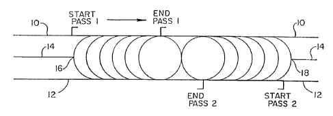
Figure 1 is a schematic showing of a multiple pass method of welding
according to the invention wherein the two passes meet at a common point.
Figure 2 is similar to Figure 1 showing overlap between the multiple
passes.
Figure 3 is a perspective view of one form of stmt which may make
use of the invention.


CA 02269558 2005-04-12
-2-
Detailed Description of Preferred Embodiments of the Invention
Refernng to Figures 1 and 2, it will be seen that a metal workpiece to
be joined consisting of two elongate pieces 10 and 12 respectively brought
into contact
at 14 may be fusion welded according to the irmention by two passes. Pass one
starts
as indicated (START PASS 1) at an outer portion 16 of a weld area and moves to
the
right in the Figure to end in a terminal pool as indicated at END PASS 1. A
second
pass (START PASS 2) begins at 18 and moves to the left in the Figure ending as
indicated in a terminal pool at END PASS 2. =fn this embodiment the welding
method
utilizes two weld passes which initiate at each end of the joint and terminate
within the
interior of the weld joint the progression of the weld passes is shown
schematically by
the succession of circular areas.
Figure 2 similarly uses two passes which move toward each other.
However, they overlap as shown in the Figure where it can be seen that PASS 1
beginning at 16 and moving to the left in the Figure and PASS 2 beginning at
18 and
moving to the right in the Figure can be seen to overlap within the weld to
form a
terminal pool.
For the purposes of this invention, as already indicated above, any of
the various known forms of fusion welding ma.y be utilized. Laser welding is
presently most preferred. The passes may be sequential or simultaneous.
Refernng to Figure 3 it will be seen that an illustrative medical stmt
may include a skeletal frame generally indicated at 2, preferably formed from
a single
nitinol wire 4, bent to form a desired configuration. The wire 4 includes a
plurality of
abutting straight portions 6 which are joined to each other by welding
utilizing the
method described in Figures 1 or 2 above. As already pointed out, a nitinol
stmt
especially benefits from this invention because nitinol stems are particularly
prone to
the problem of fracture initiation at the weld ends where terminal pools have
been
formed utilizing prior art welding techniques. The stmt shown is fully
disclosed in
U.S. patent 5,354,308 and U.S, patent 5,395,350. The stmt shown in Figure 3 is
shown here as an exemplary stmt which may make use of the method of the
invention
although the method will find application in other stmt configurations and in
other
metallic devices which require welding.


CA 02269558 1999-04-21
WO 98/17435 PCT/US97/15058
-3-
This disclosure is intended to be illustrative and not exhaustive.
It will suggest many variations and alternatives to one of ordinary skill in
this art. All
these alternatives and variations are intended to be included within the scope
of the
attached claims. Those familiar with the art may recognize other equivalents
to the
specific embodiments described herein which equivalents are also intended to
be
encompassed by the claims attached hereto.

Dessin représentatif
Une figure unique qui représente un dessin illustrant l'invention.
États administratifs

Pour une meilleure compréhension de l'état de la demande ou brevet qui figure sur cette page, la rubrique Mise en garde , et les descriptions de Brevet , États administratifs , Taxes périodiques et Historique des paiements devraient être consultées.

États administratifs

Titre Date
Date de délivrance prévu 2006-01-10
(86) Date de dépôt PCT 1997-08-27
(87) Date de publication PCT 1998-04-30
(85) Entrée nationale 1999-04-21
Requête d'examen 2002-06-04
(45) Délivré 2006-01-10
Réputé périmé 2011-08-29

Historique d'abandonnement

Il n'y a pas d'historique d'abandonnement

Historique des paiements

Type de taxes Anniversaire Échéance Montant payé Date payée
Le dépôt d'une demande de brevet 300,00 $ 1999-04-21
Taxe de maintien en état - Demande - nouvelle loi 2 1999-08-27 100,00 $ 1999-07-23
Taxe de maintien en état - Demande - nouvelle loi 3 2000-08-28 100,00 $ 2000-06-22
Enregistrement de documents 100,00 $ 2000-07-21
Taxe de maintien en état - Demande - nouvelle loi 4 2001-08-27 100,00 $ 2001-06-27
Requête d'examen 400,00 $ 2002-06-04
Taxe de maintien en état - Demande - nouvelle loi 5 2002-08-27 150,00 $ 2002-07-09
Taxe de maintien en état - Demande - nouvelle loi 6 2003-08-27 150,00 $ 2003-06-25
Taxe de maintien en état - Demande - nouvelle loi 7 2004-08-27 200,00 $ 2004-06-29
Taxe de maintien en état - Demande - nouvelle loi 8 2005-08-29 200,00 $ 2005-06-21
Taxe finale 300,00 $ 2005-10-28
Taxe de maintien en état - brevet - nouvelle loi 9 2006-08-28 200,00 $ 2006-07-07
Taxe de maintien en état - brevet - nouvelle loi 10 2007-08-27 250,00 $ 2007-07-04
Taxe de maintien en état - brevet - nouvelle loi 11 2008-08-27 250,00 $ 2008-07-09
Taxe de maintien en état - brevet - nouvelle loi 12 2009-08-27 250,00 $ 2009-07-09
Titulaires au dossier

Les titulaires actuels et antérieures au dossier sont affichés en ordre alphabétique.

Titulaires actuels au dossier
BOSTON SCIENTIFIC LIMITED
Titulaires antérieures au dossier
SCIMED LIFE SYSTEMS, INC.
WALAK, STEVEN E.
Les propriétaires antérieurs qui ne figurent pas dans la liste des « Propriétaires au dossier » apparaîtront dans d'autres documents au dossier.
Documents

Pour visionner les fichiers sélectionnés, entrer le code reCAPTCHA :


Pour visualiser une image, cliquer sur un lien dans la colonne description du document. Pour télécharger l'image (les images), cliquer l'une ou plusieurs cases à cocher dans la première colonne et ensuite cliquer sur le bouton "Télécharger sélection en format PDF (archive Zip)" ou le bouton "Télécharger sélection (en un fichier PDF fusionné)".

Liste des documents de brevet publiés et non publiés sur la BDBC .

Si vous avez des difficultés à accéder au contenu, veuillez communiquer avec le Centre de services à la clientèle au 1-866-997-1936, ou envoyer un courriel au Centre de service à la clientèle de l'OPIC.


Description du
Document 
Date
(yyyy-mm-dd) 
Nombre de pages   Taille de l'image (Ko) 
Description 1999-04-21 3 118
Dessins 1999-04-21 2 33
Dessins représentatifs 1999-06-28 1 6
Abrégé 1999-04-21 1 36
Revendications 1999-04-21 1 22
Page couverture 1999-06-28 1 29
Revendications 1999-04-22 4 138
Description 2005-04-12 3 111
Revendications 2005-04-12 4 141
Dessins représentatifs 2005-11-03 1 6
Page couverture 2005-12-08 1 30
Cession 1999-04-21 4 104
PCT 1999-04-21 8 274
Poursuite-Amendment 1999-04-21 6 176
Correspondance 1999-06-01 1 30
Cession 1999-06-04 2 97
Correspondance 1999-07-20 1 2
Cession 2000-07-21 4 214
Poursuite-Amendment 2002-06-04 1 43
Taxes 2003-06-25 1 34
Taxes 2001-06-27 1 38
Poursuite-Amendment 2004-10-12 2 59
Taxes 2002-07-09 1 43
Taxes 1999-07-23 1 34
Taxes 2000-06-22 1 38
Taxes 2004-06-29 1 36
Poursuite-Amendment 2005-04-12 10 443
Taxes 2005-06-21 1 40
Correspondance 2005-10-28 1 43