Sélection de la langue

Search

Sommaire du brevet 2271923 

Énoncé de désistement de responsabilité concernant l'information provenant de tiers

Une partie des informations de ce site Web a été fournie par des sources externes. Le gouvernement du Canada n'assume aucune responsabilité concernant la précision, l'actualité ou la fiabilité des informations fournies par les sources externes. Les utilisateurs qui désirent employer cette information devraient consulter directement la source des informations. Le contenu fourni par les sources externes n'est pas assujetti aux exigences sur les langues officielles, la protection des renseignements personnels et l'accessibilité.

Disponibilité de l'Abrégé et des Revendications

L'apparition de différences dans le texte et l'image des Revendications et de l'Abrégé dépend du moment auquel le document est publié. Les textes des Revendications et de l'Abrégé sont affichés :

  • lorsque la demande peut être examinée par le public;
  • lorsque le brevet est émis (délivrance).
(12) Demande de brevet: (11) CA 2271923
(54) Titre français: PARE-SOLEIL
(54) Titre anglais: SUN VISOR
Statut: Morte
Données bibliographiques
(51) Classification internationale des brevets (CIB):
  • B60J 3/02 (2006.01)
(72) Inventeurs :
  • PETERSON, DON MANGAS (Etats-Unis d'Amérique)
(73) Titulaires :
  • LEAR CORPORATION (Etats-Unis d'Amérique)
(71) Demandeurs :
  • LEAR CORPORATION (Etats-Unis d'Amérique)
(74) Agent: MACRAE & CO.
(74) Co-agent:
(45) Délivré:
(86) Date de dépôt PCT: 1998-07-13
(87) Mise à la disponibilité du public: 1999-01-28
Licence disponible: S.O.
(25) Langue des documents déposés: Anglais

Traité de coopération en matière de brevets (PCT): Oui
(86) Numéro de la demande PCT: PCT/US1998/014400
(87) Numéro de publication internationale PCT: WO1999/003694
(85) Entrée nationale: 1999-05-14

(30) Données de priorité de la demande:
Numéro de la demande Pays / territoire Date
893,169 Etats-Unis d'Amérique 1997-07-15

Abrégés

Abrégé français

Cette invention se rapporte à un pare-soleil pour véhicules à moteur comportant une partie centrale (12) en plastique composée d'une première (18) et d'une seconde (20) moitiés reliées par une charnière (22), une protection (14) recouvrant les première et seconde moitiés, et une pluralité de pointes disposées à proximité d'une bordure interne de chacune des moitiés. Ladite protection comporte une partie latérale recouvrant la bordure interne de chacune des deux moitiés. Les pointes (16) entre en contact avec la partie latérale de la protection (14) et se déforment de manière à se souder à la partie latérale de la protection. Des protubérances en saillie à partir d'une moitié de la partie centrale s'accouplent à des récepteurs correspondants situés sur l'autre moitié de la partie centrale de manière à maintenir ladite partie centrale repliée autour de la charnière en position opérationnelle. Cette invention se rapporte également à un procédé de fabrication de ce pare-soleil.


Abrégé anglais


A sun visor for motor vehicles is disclosed. The sun visor comprises a plastic
core (12) having first (18) and second (20) halves defined by a hinge (22), a
cover (14) covering the first and second halves, and a plurality of spikes
disposed proximate an inner periphery of each of the first and second halves.
The cover includes an edge portion overlying the inner periphery of each of
the first and second halves. The spikes (16) engage the edge portion of the
cover (14) and are deformed to bond with the edge portion of the cover.
Projections extending from one half of the core engage corresponding receptors
on the other half of the core to hold the core folded about the hinge in an
operational orientation. A method of making the sun visor is also disclosed.

Revendications

Note : Les revendications sont présentées dans la langue officielle dans laquelle elles ont été soumises.


-7-

CLAIMS

1. A sun visor for a motor vehicle, the sun
visor comprising:
a core having first and second halves, each of
the first and second halves having an inner periphery;
a cover covering an outer side of the first
and second halves, the cover including an edge portion
overlying the inner periphery of each of the first and
second halves; and
a plurality of spikes disposed proximate the
inner periphery of each of the first and second halves
of the core, the spikes engaging the edge portion of the
cover and being deformed to bond with the edge portion
of the cover.
2. The sun visor of claim 1 further
comprising at least one projection extending from the
first half of the core and at least one receptor formed
on the second half of the core, the at least one
projection engaging the at least one receptor to hold
the first half of the core proximate the second half of
the core.
3. The sun visor of claim 1 further
comprising a hinge connecting the first and second
halves of the core.
4. The sun visor of claim 3 further
comprising at least one projection extending from the
first half of the core and at least one receptor formed
on the second half of the core, the at least one


-8-

projection engaging the at least one receptor to hold
the first half of the core folded to the second half of
the core about the hinge.

5. The sun visor of claim 1 wherein the core
comprises plastic.

6. The sun visor of claim 1 wherein the core
comprises polypropylene.

7. The sun visor of claim 1 wherein the cover
comprises cloth.

8. The sun visor of claim 1 wherein the cover
comprises vinyl.

9. A sun visor for a motor vehicle, the sun
visor comprising:
a plastic core having first and second halves,
each of the first and second halves having an inner
periphery;
a cover covering the first and second halves,
the cover including an edge portion overlying the inner
periphery of each of the first and second halves;
a plurality of spikes disposed proximate the
inner periphery of each of the first and second halves
of the core, the spikes engaging the edge portion of the
cover and being deformed to bond with the edge portion
of the cover; and
at least one projection extending from the
first half of the core and at least one receptor formed
on the second half of the core, the at least one
projection engaging the at least one receptor to hold
the first half of the core proximate the second half of


-9-


the core.

10. The sun visor of claim 9 wherein the
cover comprises cloth.

11. The sun visor of claim 9 wherein the
cover comprises vinyl.

12. The sun visor of claim 9 further
comprising a hinge connecting the first and second
halves of the core.

13. A method of making a sun visor for a
motor vehicle, the method comprising:
providing a core having first and second
halves, each of the first and second halves having a
periphery and a plurality of spikes disposed proximate
the periphery;
covering the first and second halves with a
cover including an edge portion overlying the periphery
of each of the first and second halves; and
deforming the spikes to bond the spikes with
the edge portion of the cover.

14. The method of claim 13 further comprising
holding the first half of the core folded to the second
half of the core about a hinge.

15. The method of claim 13 further comprising
holding the first half of the core folded to the second
half of the core with at least one projection extending
from the first half of the core engaging at least one
receptor formed on the second half of the core.


-10-

16. The method of claim 13 wherein the core
comprises plastic.

17. The method of claim 13 wherein the core
comprises polypropylene.

18. The method of claim 13 wherein the cover
comprises cloth.

19. The method of claim 13 wherein the cover
comprises vinyl.

20. The method of claim 13 wherein the
deforming step comprises heat staking.

21. The method of claim 13 wherein the
deforming step comprises sonic welding.

22. The method of claim 13 wherein the
deforming step comprises ultrasonic welding.

Description

Note : Les descriptions sont présentées dans la langue officielle dans laquelle elles ont été soumises.


CA 02271923 1999-OS-14
WO 99/03694 PCT/US98/14400
-1-
. SUN 'VISOR
~ Technical Field
This invention relates to sun visors for motor
vehicles, and more particularly to a sun visor having a
covering bonded to a plastic core.
Backcround Art
Visors for blocking the sun and other sources
of glare have been standard equipment on motor vehicles
for many years. These visors are generally mounted to
the upper outside corner of the driver and/or passenger
side compartment, and have conventionally been
constructed with structural cores of plastic, hard board
or foam. An aesthetic covering for the core is also
normally provided with the visor. To secure the
covering to the core, it ha~~ been conventional to use an
adhesive, either alone or in combination with some
mechanical means. U.S. Patent No. 4,763,946, for
example, shows a sun visor including a polymeric core
with pins and corresponding mating recesses formed
around the periphery on opposite core halves for
compressing the edges of an upholstery material and
clamping them in a secure position as the visor halves
are brought together durincf manufacturing. Similarly,
U.S. Patent No. 4,458,938 teaches a sun visor in which
a border of the covering material is clamped in a groove
in the sun visor body.
One problem with this type of construction is
that over a period of time, the cover pulls away from
the core.


CA 02271923 1999-OS-14
WO 99/03694 PCT/US98/14400
-2-
Summary of The Invention
The present invention is a sun visor for motor
vehicles. The sun visor comprises a core having first
and second halves, and a cover covering an outer side of
the first and second halves. The cover includes an edge
portion overlying an inner periphery of each of the
first and second halves. A plurality of spikes disposed
proximate the inner periphery of each of the first and
second halves engage the edge portion of the cover and
are deformed to bond the spikes to the edge portion.
Accordingly, it is an object of the present
invention to provide a sun visor of the type described
above in which the cover is securely connected to the
core.
Another object of the present invention is to
provide a sun visor of the type described above in which
the cover is securely connected to the core without the
further use of adhesives.
These and other objects, features, and
advantages of the present invention are readily apparent
from the following detailed description of the best mode
for carrying out the invention when taken in conjunction
with the accompanying drawings.
Brief Description Of The Drawings
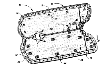
FIGURE 1 is a perspective view of a sun visor
according to the present invention in an open, unsealed
condition;
FIGURE 2 is a cross-sectional view of an edge
of the sun visor prior to a deformation operation;
FIGURE 3 is a cross-sectional view taken along
line 3-3 in Figure 1;


CA 02271923 1999-OS-14
WO 99/03694 PCT/US98/14400
-~3-
FIGURE 4 is a cross-sectional view taken along
line 4-4 in Figure 3;
FIGURE 5 is a view similar to Figure 2 and
showing an alternative method of attaching an edge
portion of a cover to the :gun visor; and
FIGURE 6 is a view similar to Figure 3 and
showing an alternative embodiment of the present
invention.
Best Mode For Carry:ina Out The Invention
With reference to the drawings, the preferred
embodiments of the present invention will be described.
Figures 1 and 2 show a sun visor 10 according to the
present invention for use in motor vehicles. The sun
visor 10 comprises a core or substrate 12, a cover 14
and a plurality of projections or spikes 16.
The core 12, which preferably comprises a
thermoplastic such as po7_ypropylene, has a general
clamshell configuration including first and second
halves respectively 18 and 20 defined by a hinge 22.
Each of the first and second halves 18 and 20 has an
outer side 24 and an inner ride 26. The cover 14, which
may for example be a foam backed cloth or vinyl, is
disposed around the visor to cover the outer sides 24 of
the core halves 18 and 20. To secure the cover around
the visor, the cover 14 is provided with an edge portion
28 that overlies an inner :periphery 30 of each of the
first and second halves.
The spikes 16 are disposed proximate the inner
periphery 30 of each of the first and second halves 18
and 20 of the core 12. As shown in Figure 2, each of
the spikes 16 initially includes a generally conical
base 32 that tapers to a point adapted to engage the
edge portion 28 of the cover. To secure the cover to


CA 02271923 1999-OS-14
WO 99/03694 PCT/US98/14400
-4-
the spikes, a two-stage process may be used. In the
first stage, a primary hold plate 34 contacts and exerts
a downward force on the folded-over edge portion 28
adjacent the spikes. This downward force causes the
spikes to substantially pierce the edge portion 28. In
the second, heatstaking stage of the operation, a
secondary heated upper die 36 is brought into contact
with the tips of those spikes which have penetrated
through the cover or, in those instances where the
spikes have not entirely penetrated the cover, into
contact with the edge portion 28 of the cover overlying
the tips of the spikes.
The die 36 is heated to a temperature of
between about 370 and 415 degrees Fahrenheit, and
remains in place for an interval of time, preferably
between about 5 and 8 seconds, which is inversely
proportional to the temperature of the die. The die may
thereafter be allowed to cool, for instance to about 150
degrees, before it is retracted to inhibit pulling the
edge portion 28 of the cover away from the spikes. As
the die is retracted, the primary hold plate 34 may be
left in place to further diminish separation of the edge
portion from the spikes. In lieu of this heatstaking
operation, the tips of the spikes 16 may be similarly
acted upon by the application of hot air, sonic or
ultrasonic welding energy. Figure 5 shows an
alternative apparatus for temporarily holding the edge
portion 28 of the cover prior to deformation of the
spikes 32. In this embodiment, a single hold plate 37
swings down as depicted by the arrow to clamp the edge
portion 28 against the inner periphery 30 while the


CA 02271923 1999-OS-14
WO 99/03694 PCT/US98/14400
-5-
heating die, sonic or ultrasonic probes, or other
equipment used to effect the spike deformation is
brought proximate the spikes 32.
Figure 3 shows that regardless of the method
employed, the tip of each of the spikes is deformed to
preferably provide a cap 38 of resolidified plastic. As
shown in Figure 4, the base 32 of each spike has a
minimum dimension, depicted by the vertical arrow, at a
location 40 where the base emerges from the edge portion
28 of the cover. In the case of a conical base, this
minimum dimension is the diameter of the base at
location 40. To facilitate: bonding of the cover 14 to
the core 12, the cap 38 preferably has a minimum
dimension, depicted by the horizontal arrow in Figure 4,
greater than the minimum dirnension of the base. Such an
arrangement provides a sufficiently secure connection
between the edge portion 28 of the cover 14 and the core
12 that there is no need for traditional hot melt glue
or other adhesives. In addition to this mechanical
bond, it should be appreciated that the base of each of
the spikes also melts to some degree and bonds with the
cover.
Figure 6 shows an alternative embodiment of
the sun visor 10 in which the tips of the spikes 32 are
flush with the outer surface of the cover, i.e. no caps
38 are formed. In this embodiment, however, the body of
the spike 32 is deformed by melting, and the bond
between the cover and the visor core is formed entirely
by the joinder of melted plastic to the cover material.
In fact, the spikes 32 ;shown in Figure 6 may not
penetrate the cover, if at all, until the application of
heat which partially melts .Localized areas of the cover.
In practice, the spikes 16 around the periphery of the


CA 02271923 1999-OS-14
WO 99/03694 PCT/US98/14400
-6-
visor halves 18 and 20 may be deformed to varying
degrees to a final shape anywhere between those shown in
Figures 3 and 6.
A series of projections 42, best shown in
Figure l, extend from the inner side of the core half 18
inboard from the spikes 16. A corresponding series of
raised receptors 44 shown in Figure 1 are formed on the
inner side of the other core half 20. After the cover
14 has been secured to the core 12 in the manner
described above, the halves are folded together about
the hinge 22 such that inclined faces of opposed legs of
each of the projections 42 engage corresponding raised
walls of the receptors 44 and the legs are biased
inwardly. After a head portion of each leg clears a
corresponding flange on each of the receptor walls, the
legs of the projections 42 spring back outwardly to
their original positions to engage the projections with
their corresponding receptors 44 to hold the visor
closed. Prior to closure, other internal components of
the visor, such as a lighted or unlighted vanity mirror,
detent clips, end clips and visor pivot rods can be
added to the visor core 12 in any conventional manner.
It should be understood that while the forms
of the invention shown and described above constitute
preferred embodiments of the invention, they are not
intended to illustrate all possible forms thereof. It
should also be understood that the worious changes may
be made without departing from the spirit and scope of
the invention disclosed.

Dessin représentatif
Une figure unique qui représente un dessin illustrant l'invention.
États administratifs

Pour une meilleure compréhension de l'état de la demande ou brevet qui figure sur cette page, la rubrique Mise en garde , et les descriptions de Brevet , États administratifs , Taxes périodiques et Historique des paiements devraient être consultées.

États administratifs

Titre Date
Date de délivrance prévu Non disponible
(86) Date de dépôt PCT 1998-07-13
(87) Date de publication PCT 1999-01-28
(85) Entrée nationale 1999-05-14
Demande morte 2001-07-13

Historique d'abandonnement

Date d'abandonnement Raison Reinstatement Date
2000-07-13 Taxe périodique sur la demande impayée

Historique des paiements

Type de taxes Anniversaire Échéance Montant payé Date payée
Le dépôt d'une demande de brevet 300,00 $ 1999-05-14
Rétablissement des droits 200,00 $ 1999-05-14
Enregistrement de documents 100,00 $ 1999-05-14
Titulaires au dossier

Les titulaires actuels et antérieures au dossier sont affichés en ordre alphabétique.

Titulaires actuels au dossier
LEAR CORPORATION
Titulaires antérieures au dossier
PETERSON, DON MANGAS
Les propriétaires antérieurs qui ne figurent pas dans la liste des « Propriétaires au dossier » apparaîtront dans d'autres documents au dossier.
Documents

Pour visionner les fichiers sélectionnés, entrer le code reCAPTCHA :


Pour visualiser une image, cliquer sur un lien dans la colonne description du document. Pour télécharger l'image (les images), cliquer l'une ou plusieurs cases à cocher dans la première colonne et ensuite cliquer sur le bouton "Télécharger sélection en format PDF (archive Zip)" ou le bouton "Télécharger sélection (en un fichier PDF fusionné)".

Liste des documents de brevet publiés et non publiés sur la BDBC .

Si vous avez des difficultés à accéder au contenu, veuillez communiquer avec le Centre de services à la clientèle au 1-866-997-1936, ou envoyer un courriel au Centre de service à la clientèle de l'OPIC.


Description du
Document 
Date
(yyyy-mm-dd) 
Nombre de pages   Taille de l'image (Ko) 
Dessins représentatifs 1999-08-05 1 24
Page couverture 1999-08-05 1 66
Abrégé 1999-05-14 1 65
Description 1999-05-14 6 251
Revendications 1999-05-14 4 114
Dessins 1999-05-14 2 76
Cession 1999-05-14 4 154
PCT 1999-05-14 5 152