Note : Les descriptions sont présentées dans la langue officielle dans laquelle elles ont été soumises.
CA 02273248 2004-10-26
1 METHOD AND APPARATUS FOR CLEANING AN IMAGE TRANSFER MEMBER
2 FIELD OF THE INVENTION
3 The present invention relates to cleaning of image
4 transfer surfaces, particularly the surfaces of image
transfer members used in liquid toner imaging.
6 BACKGROUND OF THE INVENTION
7 The use of image transfer members in electrostatic
8 imaging is well known. Typically, an intermediate transfer
9 surface is used to transfer a toner image from an imaging
surface to a final substrate. This transfer is typically
11 aided by heat and pressure.
12 Various types of intermediate transfer members are
13 known and are described, for example in U.S. Patents
14 3,862,848, 4,684,238, 4,690,539 and 4,531,825.
16
17 Belt-type intermediate transfer members far use in
18 electrophotography are known in the art and are described,
19 inter alia, in U.S. Patents 3,893,761, 4,684,238 and
q,690,559.
21
22 The use of intermediate transfer members and members
23 including transfer blankets for offset ink printing is also
24 well known. Such blankets have characteristics which are
suitable for ink transfer but are generally not usable, per
26 se, for liquid toner imaging.
27 Desirably, the transfer of the toner image from the
28 intermediate transfer surface onto the final substrate is
29 complete. However, it is appreciated that some residual
toner may remain on the surface after each transfer. The
31 residual toner typically comprises deformed toner particles,
32 some of which may be at least partially fused to other
33 particles, which may adhere to the transfer surface and may
34 accumulate to substantial amounts after many imaging cycles.
This accumulation of the residual toner particles results in
36 non-homogeneous and/or unclean transfer of the toner images
37 onto the final substrata.
38 Cleaning of intermediate transfer members is known in
39 the art. To enable continuous cleaning while avoiding
_ 1 _
CA 02273248 1999-OS-31
WO 98/25188 PCT/8.96/00173
1 erasure of the image being transferred, the cleaning station
2 in other prior art devices is located downstream of the site
3 at which the image is transferred onto the final substrate,
4 prior to the transfer of a subsequent image to the
intermediate transfer member.
6 In other known systems, the intermediate transfer
7 member is periodically cleaned by printing a series of toner
8 patterns, hereinafter referred to as "non-images", onto the
9 final substrate. Printing of the non-images is based on
applying a substantially continuous layer of fresh toner
11 onto the intermediate transfer member and transferring the
12 layer of liquid toner onto a final substrate, whereby the
13 deformed residual toner particles adhere to the fresh toner
14 and are thus removed from the intermediate transfer member.
A substantially continuous or continuous layer of toner on
16 the intermediate transfer member is typically obtained by
17 developing a substantially continuous non-image on the
18 imaging surface and transferring the developed non-image
19 onto the intermediate transfer member.
To economize on the use of liquid toner, the
21 substantially continuous non-image can be formed of a
22 plurality of screen images each of which covers only a
23 predetermined portion of the surface area of the
24 intermediate transfer member. A sequence of such screen
images, each preferably using a different color toner,
26 provides complete coverage of the intermediate transfer
27 member and collects substantially all the residual toner of
28 all the color toners. It is appreciated that different color
29 toners have different physical properties and, therefore,
some color toners are more effective, e.g. more adhesive,
31 than others in removing residual toner particles.
32 Cleaning of the intermediate transfer member by
33 printing on the final substrate, as described above,
34 generally requires at least eight imaging cycles for each
cleaning session. The final substrate bearing the printed
36 non-images which are formed during the cleaning session
37 cannot be re-used and is, thus, discarded after the
38 cleaning session, increasing maintenance costs. When the
39 imaging system is designed for printing on a continuous
- 2 -
CA 02273248 1999-OS-31
WO 98/25188 PCT/IL96/00173
1 final substrate as described, for example, in PCT
2 publications WO 96/01442 and 96/31809, each cleaning session
3 introduces a series of undesired non-images between
4 consecutive images, interrupting the sequence of images
formed on the final substrate.
6
7
8
9
11
12
13
14
16
17
18
19
21
22
23
24
26
27
28
29
31
32
33
34
36
37
38
39
- 3 -
CA 02273248 1999-OS-31
WO 98125188 PCT/8,96/00173
1 SUMMARY OF THE INVENTION
2 It is an object of some aspects of the present
3 invention to provide a method and apparatus for cleaning an
4 image transfer surface in imaging apparatus, especially in
imaging apparatus using electrostatically charged liquid
6 toner.
7 According to one aspect of the present invention, a
8 cleaning roller having a sticky surface is selectively
9 brought to contact with the image transfer surface. A toner
pattern, hereinafter also referred to as a toner non-image,
11 is developed on an imaging surface of the imaging apparatus,
12 and is transferred onto the image transfer surface. Residual
13 toner on the image transfer surface, from previous imaging
14 cycles, adheres to the fresh toner of the non-image. When
the cleaning roller engages the image transfer surface,
16 toner of the non-image is transferred onto the sticky
17 surface of the cleaning roller. Preferably, in this aspect
1$ of the present invention, the cleaning roller selectively
19 engages the image transfer surface only during predefined
cleaning sessions. Therefore, the cleaning roller can be
21 positioned anywhere along the image transfer surface, e.g.
22 upstream of the location at which images are transferred
23 onto a final substrate during normal printing. Furthermore,
24 according to this aspect of the present invention, the image
transfer surface does not engage the final substrate during
26 the cleaning sessions.
27 According to another aspect of the present invention, a
28 cleaning roller having a sticky surface continuously engages
29 the image transfer surface, collecting residual toner
particles therefrom. Periodically, a predefined toner non-
31 image is formed on the surface of the intermediate transfer
32 member and is not transferred onto the final substrate. The
33 non-image, which includes fresh liquid toner, is collected
34 by the cleaning roller and a layer of fresh toner is coated
onto the surface of the roller. Thus, according to this
36 aspect of the present invention, printing of non-images is
37 utilized to renew the stickiness of the sticky surface.
38 Since the cleaning roller continuously engages the image
39 transfer surface, the cleaning roller is positioned
- 4 -
CA 02273248 1999-OS-31
WO 98/25188 PCT/a,96/00173
1 downstream of the location at which images are transferred
2 onto the final substrate.
3 Under some circumstances, it may be desirable to
4 increase the stickiness of the toner on the roller by
heating the roller or by plasticizing the toner on the
6 roller by wetting it with carrier liquid or with a heavy
7 mineral oil having a very low volatility, a high viscosity
8 and a high flash point, such as Marcol 82. However, under
9 normal circumstances, utilizing a heated intermediate
transfer member which heats the roller by conduction, such
11 additional measures are generally unnecessary and may even
12 result in less optimal operation of the system.
13 It is appreciated that residual toner from incompletely
14 transferred images which is transferred onto the cleaning
roller accumulates gradually, over many cleaning sessions,
16 into a thick layer of dried toner which enlarges the
17 effective diameter of the cleaning roller. Therefore, in
18 preferred embodiments of the present invention, the
19 accumulated layer of toner is removed periodically from the
cleaning roller.
21 In some preferred embodiments of the present invention,
22 the non-images printed during the cleaning/surface renewal
23 sessions include "sky shot" images, i.e. images which
24 provide a substantially full coverage of the usable area of
the intermediate transfer surface. In other preferred
26 embodiments of the present invention, the non-images include
27 predefined patterns which do not fully cover the usable area
28 on the image transfer surface but which are sufficiently
29 dense to interact substantially with all the residual toner
particles. Additionally or alternatively, the non-images
31 include a series of complementary patterns which aggregate
32 to provide a substantially full coverage of the image
33 transfer surface.
34 In some preferred embodiments of the invention, only an
area of the image transfer surface corresponding to the
36 surface area of the cleaning roller is covered by the non-
37 images, whereby the stickiness of the cleaning surface is
38 renewed with minimal wastage of liquid toner. The renewed
39 sticky surface efficiently removes residual toner from the
- 5 -
CA 02273248 1999-OS-31
WO 98/25188 PCT/11.96/00173
1 image transfer surface.
2 There is thus provided, in accordance with a preferred
3 embodiment of the present invention, an imaging device
4 comprising:
an imaging surface on which images, preferably toner
6 images and more preferably liquid toner images are formed;
7 an image transfer surface which receives the images at
8 a first transfer region and from which the images are
9 transferred at a second transfer region downstream of the
first transfer region; and
11 a cleaning arrangement which engages said image
12 transfer surface at a cleaning region of the image transfer
13 surface situated between the first and second transfer
14 regions downstream of said first transfer region and
upstream of the second transfer region.
16 Preferably, the cleaning arrangement comprises a
17 cleaning surface which engages the image transfer surface.
18 In a preferred embodiment of the invention, the image
19 transfer surface receives a non-image pattern, preferably a
toner pattern and more preferably a liquid toner pattern,
21 from said imaging surface at said first image transfer
22 region and wherein said cleaning surface collects said non-
23 image pattern at said cleaning region.
24 There is further provided in a preferred embodiment of
the invention an imaging device comprising:
26 an imaging surface on which images, preferably toner
27 images and more preferably liquid toner images are formed;
28 an image transfer surface which receives the images at
29 a first transfer region and from which images are
transferred at a second transfer region downstream of the
31 first transfer region; and
32 a cleaning arrangement including a cleaning surface
33 which engages said image transfer surface at a cleaning
34 region of the transfer surface,
wherein said image transfer surface receives a non-
36 image pattern, preferably a toner pattern and more
37 preferably a liquid toner pattern, from said imaging
38 surface at said first transfer region and wherein said
39 cleaning surface collects said non-image toner pattern at
- 6 -
CA 02273248 1999-OS-31
WO 98/25188 PCT/8.96/00173
1 said cleaning region.
2 Preferably, the cleaning region is downstream of the
3 second transfer region and upstream of the first transfer
4 region.
In a preferred embodiment of the invention, the
6 cleaning surface continuously engages the image transfer
7 surface.
8 In a preferred embodiment of the invention the non-
9 image pattern comprises a pattern which provides
substantially full coverage of at least a portion of the
11 image transfer surface. Preferably, the non-image pattern
12 comprises a pattern which covers an area on said image
13 transfer surface corresponding to the area of said cleaning
14 surface. Preferably said non-image pattern comprises a non-
continuous pattern which covers predetermined portions of
16 the image transfer surface.
17 In a preferred embodiment of the invention, the
18 cleaning arrangement engages the image transfer surface only
19 during predefined cleaning sessions.
In a preferred embodiment of the invention, the
21 cleaning surface comprises a surface of a cleaning roller,
22 preferably one having a sticky surface.
23 There is further provided, in accordance with a
24 preferred embodiment of the invention, a method of cleaning
an image transfer surface in an imaging device comprising an
26 imaging surface on which images, preferably toner images and
27 more preferably liquid toner images, are formed and an
28 image transfer surface which receives images at a first
29 transfer region and from which the images are transferred at
a second transfer region, the method comprising:
31 providing a cleaning member;
32 intermittently engaging said transfer surface with a
33 cleaning member between said first and second transfer
34 regions downstream of said first transfer region.
Preferably the method further comprises:
36 developing a predefined non-image pattern on said
37 imaging surface; and
38 transferring said predefined non-image pattern onto
39 said image transfer surface at said first transfer region.
- 7 _
CA 02273248 1999-OS-31
WO 98/25188 PCT/11.96/00173
1 There is further provided in accordance with a
2 preferred embodiment of the invention a method of 'cleaning
3 an image transfer surface in an imaging device comprising an
4 imaging surface on which images, preferably toner images and
more preferably liquid toner images, are formed, an image
6 transfer surface which receives images at a first transfer
7 region and from which the images are transferred at a second
8 transfer region and a cleaning surface which engages the
9 image transfer surface at a cleaning region to remove
residual image material remaining on the transfer surface
11 after transfer of the images therefrom, the method
12 comprising:
13 periodically developing a predefined, non-image,
14 pattern on said imaging surface; and
transferring said predefined non-image pattern,
16 preferably a toner pattern and more preferably a liquid toner
17 pattern, onto said image transfer surface at said first
18 transfer region and
19 engaging said image transfer surface with said cleaning
member at said cleaning region.
21 Preferably, the non-image pattern provides
22 substantially full coverage of at least a portion of the
23 image transfer surface.
24 Preferably, the non-image pattern comprises a pattern
which covers an area on said image transfer surface
26 corresponding to the area of said cleaning surface.
27 In an embodiment of the invention, the toner pattern
28 comprises a non-continuous pattern which covers
29 predetermined portions of the image transfer surface.
Preferably, the non-image patter is transferred to the
31 cleaning surface. Preferably, the non-image pattern
32 transferred to the cleaning surface acts as a collector of
33 residual image material on the transfer surface.
34 BRIEF DESCRIPTION OF THE DRAWINGS
The present invention will be understood and
36 appreciated more fully from the following detailed
37 description, taken in conjunction with the drawings in
38 which:
39 Fig. 1 is a simplified cross-sectional illustration of
_ g _
CA 02273248 2003-09-22
wo aerxsiss ~ rcacr~c,ss~or~
7. a Qcrt~.ors of i.mag~.ng apparatccs including an arraz~gament for
2 cleaning an image transfer surface, oon$tructed and
3 c~peratxva ~.n accordance .w~.th a preferred embodiment of the
d present invention;
Flg. ~ ;ts a perspective view of the clsanirrg
6 arrangement of -f~.g. l, showing a cleaning roJ.ler thereof ire
7 a dismvur~ted condition:
8 Fig. 3 is a partial close-sectiona3. i~.lustrat3on of the
9 ovnstruot~.on of the o3.eaning roller accrsrding to a preferred
embcsdiment of the ~.nventioa;
11 fig. 4 is a kn~.fe usable for the removal of toner
12 layers from the o~.ean:Cng taller, s.n accord~snce with a
7.3 preferred embodiment of the s.nv~:ntion: and
14 Fig. 5 shows the knife of Fig, a in use.
DBTAZLED DESCRIPTxON OF fA'EFERRE17 EMBODIMENTS
16 Ref~cxence is now made to Fig. 1 ~rhiGh is s simp~,if3,ed
17 cxa~as-seatipnal il3.us~tration of imaging apparatus ~.naludirsg
1.8 an arrangement 1fl0 for clean~,ng art image tx~ansftr surface
7.9 3Z of an image transfer member 30, constxvcted axed operative
in accordance with s preferred exabodim~int of 'the px~bsen't
21 iriventic~n. The imaging apparatus 5.naludea~ an imaging surface
22 12, preferab7~p a photareaeptar surface as is known in the
23 art, ~ar example, as di$closad in U8 Patents 5.376.,97: and
24 8,508.790, mounted an a drum 14 which is rotated
in the direction indicated by an arrow ~.?.. Surface 12 engages
26 image transfer surface 32 at a first transfer region 20, where
2~
2S images formed on surface 12 are transferred onto surface 32.
29 Me'~er 30 is rotated in an opposite sense from that of drum 1Q,
3D as indicated by arrow 32, so as to produce substantially zero
31 relative motion between surface 12 and surface 32 at first
32 transfer region 20. Image transfer member 30 prexerably
33
3g includes a mufti-layered image transfer blanket 34 having a
release layer 35, as described, for example in US Patents
36 S,o89,856 or 5,047,808 or in PCf Qubl.zcations WO 94/23347 and Y
37 88/11826 or other release layers as known in the art.
38
39 As s.s known in the art, member 30 is mainta3.ned at a
.. 9 ..
CA 02273248 1999-OS-31
WO 98/25188 PCT/8.,96/00173
1 suitable voltage and temperature for electrostatic transfer
2 of a toner image from imaging surface 12. The toner image is
3 preferably subsequently transferred from intermediate
4 transfer member 30 onto a final substrate 50, such as a
paper or polymer substrate, preferably by heat and pressure,
6 at a second transfer region 25. Pressured contact between
7 surface 32 of member 30 and substrate 50 at region 25 is
8 preferably provided by an impression roller 40 which rotates
9 in a direction opposite that of member 30, as indicated by
arrow 41. Such second transfer is very well known in the
11 art.
12 In some preferred embodiments of the present invention,
13 multi-color images are produced by sequentially transferring
14 a plurality of single color images, in alignment, onto
surface 32 of member 30. A complete multi-color image formed
16 of the plurality of single color images is subsequently
17 transferred, in one action, onto the surface of final
18 substrate 50. In these preferred embodiments of the present
19 invention, substrate 50 is inserted into region 25 and urged
against surface 32 by impression roller 40 only during the
21 transfer of the multi-color image. Between multi-color
22 transfers, intermediate transfer member 30 and impression
23 roller 40 are disengaged. Alternatively, each single color
24 image may be separately transferred to substrate 50 via
intermediate transfer surface 32, as known in the art.
26 In some preferred embodiments of the present invention,
27 a plurality of toner images are sequentially printed on a
28 single, continuous, substrate 50, as described, for example
29 in PCT publications WO 96/01442 and WO 96/31809. In these
preferred embodiments of the present invention, substrate 50
31 is not continuously in contact with image transfer surface
32 32 of member 30, in order to enable repositioning of
33 substrate 50 vis-a-vis surface 32 between imaging cycles. As
34 described below, substrate 50 is also disengaged from
surface 32 during cleaning and/or surface renewal sessions
36 in accordance with preferred embodiments of the present
37 invention.
38 As described above, image transfer blanket 34
39 preferably includes release layer 35 which is outermost on
- 10
CA 02273248 1999-OS-31
WO 98/25188 - PCTIIL96/OOI73
I the blanket when it is mounted on member 30. Release layer
2 35 is preferably about 100 micrometers thick and is
3 preferably formed of a silicone material. Details of a
4 preferred release layer 35, including preferred processes of
forming release layers, are described in the aforementioned
6 PCT publications WO 94/23347 and WO 96/11426.
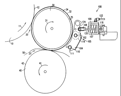
7 Reference is now made also to Fig. 2 which
8 schematically illustrates a perspective view of a preferred
9 cleaning arrangement 100, showing a cleaning roller 105
thereof in a dismounted condition. As shown in Figs. 1 and
11 2, cleaning arrangement 100 includes carrier arms 104 having
12 fork-shaped bottom ends 111 which are supported on pivot
13 axles 110, such that arms 104 are pivotable about axles 110.
14 Arms 104 are substantially parallel and are preferably
supported by connecting bars 120. Cleaning roller 105 is
16 mounted between parallel arms 104 using bearings 116 which
17 enable free rotation of roller 105 about its longitudinal
18 axis. Axles 110 are preferably fixedly mounted to a support
19 structure of the imaging apparatus.
Roller 105 (shown in greater detail in Fig. 3)
21 preferably includes an inner, preferably metal, core 102
22 covered with layer 114 of a relatively soft resilient
23 material such as polyurethane. Preferably, the layer has a
24 thickness of 25-35 micrometers at the cE.nter of the roller
and a Shore A hardness of 20-25. Layer 11~= is thinner at the
26 ends of the roller in order to provide higher pressure
27 thereat to aid in removing toner which te:zds to accumulate
28 along the edges of the intermediate trar:sfer member. It
29 should be clear that thicker or thinner layers and/or harder
or softer material may be used for layer 114 depending,
31 inter alia, on the characteristics of th~: intermediate
32 transfer member, the toner and the tempe.:-ature of the
33 roller. Layer 114 has been found to be sufficiently sticky
34 to toner on surface 32 of member 30 to enaY~le efficient
collection of residual toner, as described, in detail,
36 below.
37 In a preferred embodiment of the invention, as shown in
38 Figs. 1 and 2, upper portions 124 of arms 104 are connected,
39 via connectors 108, to respective pistons 126 01 actuators
- 11 -
CA 02273248 1999-OS-31
WO 98/25188 PCT/IL96/00173
1 106, which preferably include air-pressure actuators. When
2 air pressure is supplied to actuators 106, via air-pressure
3 inlet 122, pistons 126 move towards image transfer member 30
4 pushing connectors 108 which, in turn, push upper portions
124 of arms 104. This results in forceful motion of cleaning
6 roller 105 towards member 30, urging the surface of layer
7 114 of roller 105 against image transfer surface 32. When
8 the supply of air-pressure to actuators 106 is deactivated,
9 springs 107 in actuators 106 push pistons 126 away from
member 30, causing disengagement between roller I05 and
11 surface 32. In a preferred embodiment of the invention, the
12 supply of air-pressure to actuators 106 is selectively
13 activated, to produce selective engagement between roller
14 105 and intermediate transfer member 30 only during cleaning
and/or surface renewal sessions as described below. As
16 further shown in Figs. 1 and 2, actuators 106 are preferably
17 fixedly mounted on a support rod 118 which is fixedly
18 mounted to the support structure of the imaging apparatus.
19 It should be appreciated that air-pressure actuators
106 may be replaced by any suitable means known in the art
21 for producing selective engagement between cleaning roller
22 105 and intermediate transfer surface 32. For example,
23 hydraulic actuators or any other type of actuators may be
24 used in place of actuators 106.
In accordance with preferred aspects of the present
26 invention, sticky surface 114 is selectively brought to
27 contact with the image transfer surface only during
28 predefined cleaning sessions. At the beginning of each
29 cleaning session, a liquid toner pattern, hereinafter
referred to as a toner non-image, is developed on imaging
31 surface 12, and is transferred onto surface 32 of member 30
32 as is known in the art. The non-image developed on surface
33 12 may be a "sky shot" image, i.e. an image which provides a
34 substantially full coverage of the operative area of
intermediate transfer surface 32.
36 Alternatively, the non-image developed on surface 12
37 includes a predefined pattern which does not fully cover
38 the operative area of the image transfer surface but which
39 is sufficiently dense to interact substantially with all
- 12 -
CA 02273248 1999-OS-31
WO 98125188 PCT/IL96100173
1 residual toner on surface 32, as described below. Such a
2 non-image is referred to herein as having "substantially
3 full coverage." In some preferred embodiments of the
4 invention, a series of complementary patterns are
sequentially transferred onto the image transfer surface,
6 which patterns aggregate to provide at least a substantially
7 full coverage of at least a portion of the image transfer
8 surface.
9 It should be appreciated that residual, typically
deformed and generally partially fused, toner particles,
11 accumulated over imaging cycles prior to the cleaning
12 session, adhere to the toner non-image on image transfer
13 surface 32. When the sticky surface of cleaning roller 105
14 engages surface 32, the toner non-image is removed from the
image transfer surface together with the residual toner
16 particles. Furthermore, the fresh toner transferred onto
17 roller 105 during the cleaning session enhances the
18 stickiness of its surface and, thus, further engagement
19 between surface of roller 105 and surface 32, without adding
additional toner, may be utilized to remove additional toner
21 particles from surface 32.
22 In some preferred embodiments of the present invention,
23 only an area of image transfer surface 32 corresponding to
24 the area of layer 114 is covered by the non-images, whereby
the stickiness of the cleaning surface is renewed with
26 minimal wastage of liquid toner. The renewed sticky surface
27 efficiently removes residual toner from the image transfer
28 surface.
29 Since cleaning roller 105 preferably engages surface 32
only during the cleaning sessions, the cleaning roller can
31 be positioned anywhere along the image transfer surface,
32 e.g. along the portion of surface 32 downstream of first
33 image transfer region 20 and upstream of second image
34 transfer region 25, as shown in Fig. 1.
It is appreciated that the toner transferred onto layer
36 114 of cleaning roller 105 accumulates gradually, over many
37 cleaning sessions, into a thick layer of dried toner which
38 enlarges the effective diameter of cleaning roller 105.
39 Therefore, in preferred embodiments of the present
- 13 -
CA 02273248 1999-OS-31
WO 98/25188 PCTIIL96/00173
1 invention, the accumulated layer of toner is removed
2 periodically from the cleaning roller. To remove the
3 accumulated toner layer from layer 114, roller 105 is
4 preferably dismounted, as shown in Fig. 2, and a sharp knife
or other tool is used to cut through the layer of dried
6 toner which may, then, be peeled off layer 114.
7 Alternatively, roller 105 may be periodically replaced.
8 Figs. 4 and 5 respectively show a preferred embodiment
9 of a knife 150 suitable for removing a toner layer 160
IO without damaging layer 114 and an illustration of the knife
11 performing this function. Knife 150 includes a handle 152, a
12 lifter portion 154 mounted at one end of the of the handle
13 and a knife blade 156 situated to cut toner layer 160 which
14 is lifted by lifter portion 154. The lifting and cutting
process is illustrated in Fig. 5.
16 In a preferred embodiment of the present invention, the
17 following cleaning sequence is used for each cleaning
18 session. First, at least one "dry run" is performed, whereby
19 cleaning roller 105 engages surface 32 but toner is not
applied to surface 32. At this stage, some of the excess
21 liquid on roller 105 is evaporated and less deformed toner
22 particles are collected onto its surface. Then, at least one
23 non-image as described is transferred onto surface 32. The
24 fresh liquid toner of the non-image collects the residual
toner and is coated onto layer 114 as described above.
26 Finally, at least one additional "dry run" is performed to
27 ensure maximal removal of the residual toner.
28 In accordance with other preferred aspects of the
29 present invention, the sticky surface of cleaning roller 105
continuously engages image transfer surface 32, collecting
31 residual toner particles therefrom. It is appreciated,
32 however, that the residual toner, which is typically dry
33 and deformed, degrades the stickiness of the surface.
34 Therefore, according to these aspects of the present
invention, a toner non-image as described above is
36 periodically transferred onto the surface of the
37 intermediate transfer member to renew the stickiness of the
38 surface of roller 105. The non-image, which includes fresh
39 liquid toner, is collected by cleaning roller 105 and a
- 14 -
CA 02273248 1999-OS-31
WO 98/25188 PCT/IL96/00173
1 layer of fresh toner is coated onto layer 114. As described
2 above, the renewed surface efficiently removes residual
3 toner particles from surface 32. Since, in these aspects of
4 the invention, cleaning roller 105 continuously engages the
image transfer surface, the cleaning roller must be
6 positioned downstream of second transfer region 25, contrary
7 to the non-continuous embodiment shown in Fig. 1, which may
8 be positioned anywhere on the intermediate transfer member.
9 In those systems where a plurality of toner images are
accumulated on the transfer member prior to transfer
11 therefrom, the roller must be disengaged from the transfer
12 member while the images are being accumulated.
13 It should be understood that some aspects of the inven-
14 Lion are not limited to the specific type of image forming
system used and some aspects of the present invention are
16 also useful with any suitable imaging system which forms a
17 liquid toner image on an image forming surface and, for some
18 aspects of the invention, with powder toner systems. Some
19 aspects of the invention are also useful in systems such as
those using other types of intermediate transfer members
21 such as belt or continuous coated drum type transfer
22 members. Some aspects of the invention are suitable for use
23 with offset printing systems. The specific details given
24 above for the image forming system are included as part of a
best made of carrying out the invention; however, many
26 aspects of the invention are applicable to a wide range of
27 systems as are known in the art for electrophotographic and
28 offset printing and copying.
29 It will be appreciated by persons skilled in the art
that the present invention is not limited by the description
31 and example provided hereinabove. Rather, the scope of this
32 invention is defined only by the claims which follow:
33
34
36
37
38
39
- 15 -