Note : Les descriptions sont présentées dans la langue officielle dans laquelle elles ont été soumises.
CA 02281093 1999-08-13
WO 98/36976 PCT/US98/03122
HIGH STRENGTH CONTAINER
Field of the Invention
This invention relates strength, lightweightcontainers.
to high More
particularly,this invention relatescontainers that a high longitudinal
to have
and lateralstrength and a reducedlateral deformationwhen filled
with a
substance.
Background of the Invention
There is a continuing need for lightweight containers that have a high
longitudinal and lateral strength. A high longitudinal and lateral strength
container resists both bulging and paneling. Paneling is when some of the
head space gases are absorbed by the contents of the bottle to create a slight
vacuum. This can cause the front or rear wall to buckle inwardly. A container
will bulge when the wall strength is less than the force exerted on the
container
walls by a contained substance or from container stacking. Both of these
effects are problems. Each changes the original shape of the container.
There also is a need for lightweight, high strength containers at the
manufacturing and distribution levels. The containers must be sufficiently
strong to withstand the forces during filling and handling, and then later
during
distribution when packing cases and/or the containers will be stacked, one on
the other. Also there must be a sufficient strength when handled by the
consumer during use. The container must retain its integrity so that there
will
be no spills or other such events.
_j_
_ .. . . . . . , ,,_.... _ .. . _ _. . _ _. . ._._. . . _
CA 02281093 1999-08-13
There is a continuing need for containers that have a lighter Height. -!-his
results in a lower cost and less material to rscycle cnce the contair~er is
emp-.ied
of its contents. The problem is i-~ow to make a lightweight contGiner that
will
substantially retain its shape dur7ng usage, that is, how to make a cottle
that has
a high lateral and longitudinal strenath. These are competing cbjectives.
This probicm a partially acdressed by the Per,~ol) product bet;le. This ~s a
merman product. In this hot"e there are .rant and rear ;malls and connecting
sidewails. There also are flat sections between each o' these waits. This
bottle
partially salves the problem. Howeve,~, in order to get lightweight container
and
higr longitudinal and lateral strength between the front wall and tr.e
sidewalls,
and between the rear wall and th$ sidewalls, there should ae concave
transition
walls. A concave shape to a transition wail ir~creases the strength of the
container both laterally and iongitrrdinaily. In addition, it has been fund
that the
handle area can ;ikewise be strengthened if between the wall of the handle
araa
and the front, rear and sidewalls, there also is a concave tr ansiticr wall. T
hat is,
in any transition from one canta~ner wall to anotr,er container waif there
should be
a concave transition wall. A transition wall with a ~ncave stn ucture permits
the
use of less container matanal but yet retains the overall container strength.
U.S. Patent 4,312.455 discloses a container with tvro convex comer walls
and two ;,cncave-like corner walls. The concave-like walls are forme~ by
longitudinal ribs. The container also has a hand4e, but with no effort to
strengthen
the handle area. This container, white stronger than the prior art bottle
shown in
Figure 1 of the patent, requires design improvements to achieve a lighhweight
bottle status.
Brief SurnmarXof the !nveniion
The container has a fronf wall, a rear wall and sidewalls connec:irg the
fr ont wail and the rear wall. The container is closed at the bcttom end by a
bottom wall with a dispensing channel at the other end. Between, the front
wall
and each sidewall, and the rear wall and each sidewalk there is a concave
transition wail. The concave transition wall e~ctends from about the bottom
wolf
up to at least about half the distance to the dispensing channel. In an upper
.2_
CA 02281093 1999-08-13
WO 98/36976 PCT/US98/03122
part of the container the concave transition walls can merge into the
structure
of the container.
The container has a handle which preferably is comprised of an
aperture in the front wall which extends to the rear wall. An aperture wall
connects the front wall to the rear wall. Between the aperture wall and the
front wall and the aperture wall and the rear wall, there are concave aperture
transition walls. In the handle area of the container the concave transition
wall
for purposes of the extension up the container includes the aperture concave
transition walls which also strengthen the handle side of the container.
The concave transition walls and the aperture concave transition walls
serve to increase the lateral strength of the container. These concave
transition walls reduce the longitudinal and lateral distortion of the
container
when the container is filled with a substance. Also, they provide for a handle
that undergoes minimal deformation when the handle is gripped.
The upper part of the container in a preferred embodiment will have a
dome shape with hyperbolic walls. The hyperbolic walls transfer longitudinal
forces on the container downwardly to the body of the container and to the
walls of the container with the concave transition walls functioning as
columns
to assist in the transfer of the longitudinal forces to the base and the
bottom
wall.
The bottom wall preferably will have at least one longitudinal concave
portion and at least one concave lateral portion. More preferably for larger
size containers, there are at least two concave lateral portions. The concave
portions increase the strength of the bottom of the container.
-3-
CA 02281093 2005-12-07
62301-2092
An aspect of the invention provides a container
comprising a front wall, a rear wall and sidewalls joining
said front wall and said rear wall, a bottom wall closing a
base end of said container and a dispensing channel at a top
end of said container, a concave transition wall at each
junction of said front wall and said rear wall with said
sidewalls, first concave transition walls, of the concave
transition walls, adjacent a first sidewall of the
sidewalls, extend from approximate said base end to at least
half the distance to said dispensing channel, said concave
transition walls forming strengthened portions of said
container thereby increasing the longitudinal and lateral
strength of said container, an integral handle comprising an
aperture in said front wall which extends to said rear wall,
an aperture wall, a concave aperture transition wall
connecting said aperture wall to said front wall and to said
rear wall.
-3a-
CA 02281093 1999-08-13
WO 98/36976 PCT/US98/03122
Brief Description of the Drawin4s
Figure 1 is an elevational view of the container.
Figure 2 is a left side elevational view of the container.
Figure 3 is a right side elevational view of the container.
Figure 4 is a top plan view of the container.
Figure 5 is a bottom plan view of the container.
Figure 6 is a cross-sectional view of the container along line 6-6 of
Figure 1.
Figure 7 is a cross-sectional view of the container along fine 7-7 of
Figure 1.
Figure 8 is a front view of an alternate bottom wall of the container.
Figure 9 is a side view of the alternate bottom wall of the container.
Figure 10 is a bottom plan view of the alternate bottom wall of the
container.
-4-
T ~
CA 02281093 1999-08-13
WO 98/36976 PCT/US98/03122
Detailed Description of the Drawings
The invention will now be described with specific reference to the
drawings.
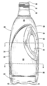
In Figure 1 there is shown a is a front elevational view of a container of
the present invention. The container 20 has a front wall 22, right sidewall 26
and left sidewall 24. At the lower end there is a base 40 with two concave
recesses 42. The top portion 25 of the body of the container is dome shaped
with hyperbolic shaped walls. At an upper part of the top portion, there is a
cylindrical section 48 which has threads 44. Aperture 46 is for filling and
dispensing materials from the bottle.
Between the front wall 22 and the sidewall24 there is a concave
transition wall 30 and between the front wall 22 and sidewall 26 there is a
concave transition wall36. These concave transition walls provide both
longitudinal and lateral strength to the bottle. The concave transition walls
extend from the base 40 up to the upper portion of the bottle 25. At this
point
the concave transition walls merge into the structure of this part of the
container. The base of the bottle has concave recesses 42 which add strength
to this part of the container.
The container also has a handle which is comprised of aperture 50
which extends through the bottle. This aperture extends from front wall 22
through to the rear of the container. Aperture wall 52 connects to the front
wall
and rear wall by means of concave aperture transition wall 54. This concave
aperture transition wall strengthens the sidewall 26 in the area of aperture
50.
Figure 2 is a view of the left side of the container. There is shown here
left sidewall 24 in more detail. Also shown is rear wall 28. concave
transition
wall 32 connects the rear wall and left sidewall. In this view it is seen that
the
concave transition walls extend down and through the base 40. Also shown is
single concave recess 41 in the base of the container. This concave recess
strengthens the bottom of the bottle.
-5-
CA 02281093 1999-08-13
In Figure 3 t>iere is shown a view of the left side of the ccnta~ner. Tr,e
aperture wall 52 tine' the concave aperture transition wall ~ is shown in more
detail in
this view. This concave aperture transition wail 54 strengthens the hanale,
end in
particular, area 26(a) ef sidewall 26 which corr:prises a part of the nardle.
''he
concave aperture tray anion ~Nalls and the relanveiy narra~.v partian Z6ta)
ser; a ;o -orrn
a strengthened uerical column m this cart of the '=ontainer. Such a nerti~l
cclurr,r
feature incre2sea the longitudinal stn ength of '~~s side or the c:~rtainer by
a ~ .,pro
effective transfer of forces to the bass.
Figure 4 is a is a top plan view of the container. This vie~N shows each of
the
walls and the concave recess 41 in the bottom of the oottle. Figure 5 is a
bottom plan
view of the container. This shows the shcrt lateral ~ancave recesses 42 and
the
longer lateral rerxss 41. Each of the short concave ;atonal recesses merges
intc the
longer concave lateral recess.
1~
Figure 6 is a is a cross-sectional view of the container of Figure 1 through
line
6-6. This ~~~w show: the container body concave transition walls 30, 32, 34
and 36 in
more detail. The structure of the bottom surface also is shov~rn in more
detail. Lateral
concave rec;2sses .49 and d2 fom; a plurality of ,~.ontainer support surfaces
80 anC 6c.
Figure r' is a is a cross-sectional view of the container along !ine 7-7 of
Figure 1. This shows ttte front wall 22 and rear wall 23 and the concave
transition
wails. Also sho~~n m detail is the handle area. bb'ali 52;b), concave aperture
tr2r~SitiOn
walls 54 and 56 and sidewaU 24 enclose area 51 which is essentially a bellow
vertical
column. The wail 52;b) has a concave shape which provides additional strength.
Tne
aperture wall 52(a) is the wal! between, the main body of the container and
the
crescent-shaped handle aperture 50. The 'eatures of the bct'om surface aVso
are
shown in this view.
CA 02281093 2005-12-07
62:101-2092
Figures 8 through 10 shows an alternate base for the container; Here
container 70 has a front wall 72 and a rear wall 71. There are shown two
concave body transition walls 74 and 76. These separate the front wail from
the sidewalls 84 and 86 respectively. The base portion 78 has a single short
lateral concave recess, in Figure 9 there is shown ~a side view of this bottle
base. Sidewall 84 is abutted by concave transition walls 73 and 74 which
separate this sidewall from rear wall 71 and front wall 72 respectively. There
also is shown.a single longitudinal recess 82 and two lateral recesses
80 in the base.
Figure 10 shows this alternate base in more. detail. The concave
recesses are shown in more detail. These recesses create container support
surfaces 88 and 90.
By the .use of concave shaped surfaces in the base and in the body of
the container, a container can be produced that used a decreases a(nount of
plastic. The weight of the bottle can be reduced up to 25%. The concave
surfaces are strong surfaces and forrti a strong body portion and bottom to
the
container. The upper part of the container being comprised of hyperbolic
surfaces provides for a strong upper portion and a good technique for
transferring a weight placed on the top of the container down the various
walls
to the base. This is a weight seen many times in the stacking of the
containers.
The containers can be constructed from a wide range of materials. The
preferred materials are plastics, and preferably, polyolefin monomers and
copolymers and polyesters. Suitable polyolefins include polyethylenes,
polypropylenes, the vinyl polymers such as vinyl chloride, vinyl acetate and
vinyl alcohol polymers, and various copolymers of these polymers. Suitable
polyesters include polyethylene terephthalate and polybutylene terephthalate.
CA 02281093 1999-08-13
WO 98/36976 PCT/US98/03122
Various modifications can be made to the concepts of the present
invention. However, these are within the present disclosure which sets out
how to produce a strong container using less container structured material.
_8_
T. ~