Note : Les descriptions sont présentées dans la langue officielle dans laquelle elles ont été soumises.
CA 02281330 1999-09-03
Apparatus for Personalizing Identification Cards
The invention refers to an apparatus for personalizing identification
cards with integrated circuits as per the preamble of claim 1.
This type of apparatus is known from DE 196 94 306 Al. The personalizing
station consists of a printing station which allows imprinting
identification cards with integrated circuits, so-called chip cards, as
per IS07816-2. The rotor serves to turn the cards to allow printing on
both sides. While printing takes only a few seconds, chip loading is
more time-intensive. To make good use of the card-turning time, the
above apparatus has several contacting devices installed on the rotor
which allow the loading of chips at same time the cards are being
turned.
To feed the cards to the individual contacting devices, the above
apparatus requires a corresponding number of card transport devices on
the rotor. The power supply to the motors of the card transport devices
and of the contacting devices thus requires a large number of electrical
lines which restrict the mobility of the rotor. The number of contacting
devices is therefore limited so that the time for loading the chips is
in the final analysis limited by the output speed of the cards,
especially when large quantities are data need to be loaded, as for
example with processor chips.
EP 0 597 135 A1 describes a device for the reading and writing to
magnetic cards with a rotor, along whose circumference is provided a
pocket for the coding of magnetic strips, and with chip cards one more
pocket with a chip reading station
The problem of the invention is to substantially increase the output
speed of personalized identification chip cards in a simple manner.
This is achieved by the invention with the apparatus described in claim
1. The subclaims describe further advantageous developments of the
invention.
CA 02281330 1999-09-03
2
In the apparatus as per the invention, the contacting devices for the
loading of the .chips are arranged in a stationary position along the
circumference of the rotor. The rotor thus forms a type of rotary disk
for transporting the cards to the individual contacting devices for
loading the chips.
To transport the cards from the rotor to the individual contacting
devices and return them after loading from the contacting devices to the
rotor, each contacting device is assigned a card transport device. It is
possible to use commercially available units which draw in the chip
card, load it and eject it after loading. The transport of the chip
cards inside these devices can be controlled by sensors.
Due to the stationary nature of the array, the electrical lines for the
power supply to the motors of the card transport devices, of the chip
contacting devices and of the sensors can be laid without problem.
The card transport direction of the chip loading devices extends
radially. This allows a large number of chip loading devices to be
radially arranged around the rotor and permits making the loading time
a corresponding multiple of the processing time of each card in
subsequent personalizing stations, for example a multiple of the card
printing time in the printing station or stations.
The apparatus of the invention therefore allows to load large quantities
of data into memory chips, also and in particular programs into
processor chips.
While the fixed chip contacting devices are arranged along the
circumference of the rotor, in the apparatus of the invention the
subsequent contacting device on the rotor is used for test reading the
chips.
Test reading can be performed in different ways. For example the chips
with the contacting devices on the rotor can be tested before being
programmed by the chip contacting devices installed fixed around the
rotor.
CA 02281330 1999-09-03
3
In this way, unusable cards can be determined. These may be cards, for
example, with a defective chip or a card with a type of chip not
compatible with the personalizing apparatus. The unusable card can be
extracted using an ejection device arranged in a stationary position
along the circumference of the rotor and thus be excluded from
subsequent processing by the apparatus of the invention.
After the chips are loaded by the chip loading units arranged around the
rotor, the test reading device at the rotor permits reading the data on
the chips. The read data can then be used to verify whether the chips
have been correctly loaded, in particular for the purpose of
coordinating the chip data with the data from at least one other
subsequent personalizing station.
The other data may, for example, be graphic and/or magnetically stored
data. Thus, the subsequent personalizing station may be a printing
station which imprints the card with the personal data and/or a picture
of the card holder.
An embossing apparatus may be provided for imprinting alphanumeric data
on the card to project from the card.
The printing station can furthermore be made up of a thermal printing
head which consists of heating elements arranged in a row and running
perpendicular to the card transport device and which can be individually
computer-operated. The individual speed of the card transport device is
provided with a step motor which moves the card along the row of heating
elements at a step rate that corresponds to the number of heating
elements.
The card can also be provided with a thermally sensitive layer or a
colour transfer film may be provided which is moved along between the
card and the thermal printer head. The thermal printer head of this type
allows to imprint both numerical data and a picture of the card holder
onto the card.
CA 02281330 1999-09-03
4
When the identification card contains a magnetic strip, the subsequent
personalizing station may also be a coding station for programming the
magnetic card.
Thus, the chip test reading device at the rotor of the apparatus of the
invention serves in particular for verifying the correspondence of the
personal data of the chips loaded by the chip loading devices with the
card data, printed or to be printed and/or coded. The test reading
apparatus needs to read only a small portion of the data on the chips to
verify their correspondence with the printing and/or coding station, for
example. The time needed for test reading the chips is therefore
correspondingly short.
After the return transport from the chip loading devices to the rotor,
the cards are turned by the rotor into the direction of the
personalizing station or stations or ejection unit to be thereafter
transported by the card transport apparatus on the rotor to the
neighbouring personalizing station or stations or ejection unit.
The time for turning the cards is sufficient for the test reading by the
chip contacting device of the rotor. The test reading does therefore not
affect the output speed of the cards.
Moreover, as in the apparatus of the invention, the loading time in the
chip loading devices arranged around the rotor is a multiple of the
processing time of the cards in subsequent personalizing stations, for
example the printing station or the magnetic card coding station, the
invention makes it possible to load large quantities of data with the
chip loading devices and to test read the chips . Inspite of this fact,
the output speed of the cards is substantially raised, possibly in such
a way that the card output speed is no longer determined by the loading
of the chips but by the processing of the cards in subsequent
personalizing stations, like the printing station or magnetic strip
coding station.
When at least one other personalizing station is arranged after the
rotor, the chip cards can be directly fed to the rotor which will then
CA 02281330 1999-09-03
refeed them one by one, i . a . to the individual chip loading apparatuses
arranged around it.
However, the subsequent personalizing station, or when there are several
personalizing stations, one of these, can also be arranged before the
rotor. Thus, a printing station may be provided before the rotor, for
example. The rotor can then be used for turning the card by 180 degrees
which allows imprinting the card by this printing station on both sides,
as described in detail DE 195 19 999 C2. Another possible setup is to
arrange one printing station before and one printing station after the
rotor so that the card can be printed by one printing station on the one
side and, after turning by the rotor, by the other printing station on
the other side.
Thus, the card can be turned by the rotor for further processing. The
turning of the card by the rotor may also be done merely for the purpose
of onward transport, for example to stack or deposit the completed
personalized card in the output station in a certain manner, for example
with the front side facing up or down.
Identification cards in the sense of the invention are both identity
cards, i.e. cards which identify the holder or certify him to be a
member of a certain group, as well as access cards, i.e. cards which
entitle the holder to claim certain services.
As an example, one of the versions of the apparatus of the invention is
explained below by way of example in greater detail in conjunction with
the drawing. The drawing shows schematically
Fig. 1: a longitudinal section of the apparatus
Fig. 2: a partial reproduction of a section along Line II-II of Fig. 1;
and
Fig. 3: a partial view of the rotor as per Fig. 1
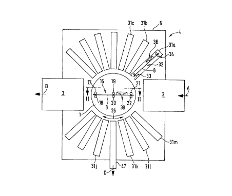
As per Fig. 1, rotor 1 is arranged between two printing stations 2 and
3. As shown in particular in Fig. 2, the rotor 1 is pivoted with shaft 7
between lateral walls 5 and 6 of casing 4. I.e., rotor 1 is can be
rotated around an axis which i.s positioned in the card plane
CA 02281330 1999-09-03
6
perpendicular to the longitudinal axis of card 8. Rotor 1 is powered by
step motor 9.
Rotor 1 incorporates two disk-shaped lateral walls 11 and 12 which are
interconnected by Struts 13. Lateral Walls 11 and 12 of rotor 1 are
provided on their inner sides with grooved tracks 14 and 15 into which
card 8 engages with its longitudinal edges.
The transport of card 8 in rotor 1 is provided by card transport device
16. The card transport device 16 consists, for example, of three pairs
of rolls 17, 18; 19, 20 and/or 21, 22 on the one side and/or the
opposite side of card 8. Rolls 17 to 22 are powered by a motor, not
shown, attached to rotor 1 via sprocket gear 23, schematically shown in
Fig. 2.
Paired rolls 21 and 22 pick up card 8 when the card leaves printing
station 2 after having been imprinted on its upper side by printing
station 2.
Card transport device 16 thus moves Card 8 in radial direction of rotor
1 in either direction. Rotor 1 carries sensors 24 and 25, for example
light barriers, at both end of card transport device 16.
Rotor 1 can be rotated with motor 9 in both directions shown by the two-
headed arrow 26 (Fig. 1).
In the position shown in Fig. l, card transport device 16 of rotor 1
points with one end at printing station 2 in such a way that card 8 can
be fed from printing station 2 to rotor 1. This rotary position of rotor
1 can be defined as its basic position from which the control and speed
of the rotation of rotor 1 is performed with step motor 9.
To define this basic position, a device 27 is provided which as shown in
Fig. 2 consists for example of a projection 28 on lateral wall 11 of
rotor 1 and a light barrier with light source 29 and a photocell 30 on
casing wall 5.
CA 02281330 1999-09-03
7
As per Fig. 1, a large number of chip loading devices 31a-m is arranged
around rotor 1 and face away radially from rotor 1.
Chip loading stations 31a-m are attached between the two walls S and 6
of casing 9, i.e. in a stationary position. As all are of the same
shape, only chip loading station 31a is shown in greater detail in Fig.
1. Accordingly, each chip loading station 31a-m features a card
transport device 32 which is essentially shaped in the same way as card
transport device 16 of rotor 1. I.e., card transport device 32 of chip
loading station 31a-m features pairs of rolls 33 and 34 which are
arranged on one and/or the other side of card 8 and driven by a gear,
not shown, powered by a motor, not shown, in order to pick up card 8
from rotor 1 and draw it in and return it to rotor 1 in the opposite
direction after loading of chip 35 on card 8 (Fig. 3).
For the loading of chips 35, each Station 31a-m is equipped with a
contacting device 36 for loading which may have the form of contacting
device 38 on rotor 1 for test reading, which is shown in greater detail
in particular in Fig. 3 and will be explained below.
Each chip loading station 31a-m may, moreover, carry sensors, not shown,
for example contacts, which determine the position, for example the
final position of card 8 in the current chip loading station 31a-m, in
which the loading of chips 35 takes place.
As shown in Fig. 2, rotor 1 has a contacting device for reading chips
35. A shown in Figs. 2 and 3, contacting device 38 consists of a plate
40, of plastic for example, in which Chip Contacts 42 are located on
spring-loaded arms 43 inside slots 41 which extend in card feeding
direction. Arms 43 are equipped with contacts 44 which are connected to
the computer system, not shown, employed to operate contacting device
38.
The electrical lines for the supply of the electrical devices on rotor 1
are bundled into cable bundle 96 which turns together with rotor 1.
CA 02281330 1999-09-03
8
On the lower side of rotor 1 between walls 5 and 6 of casing 1 is
installed a pocket 47 into which unusable or incorrectly loaded cards
can be ejected into a container not shown.
The unprinted and unloaded chip blanks are fed to printing station 2 in
the direction of arrow A. At the beginning of the personalizing
process, a card printed on one side by printing station 2 is fed to
rotor 1 in the basic position shown in Fig. l, i.e. it is drawn in by
card transport device 16 of rotor 1.
Rotor 1 is rotated by step motor 9 which in turn is controlled by the
computer system in order to feed card 8 to the next following empty chip
loading station, for example 31a, by activating card transport device 16
of the rotor and to card transport device 32 of chip loading station
31a. Rotor 1 then returns to its basic position and the process is
repeated as often as needed until all chip loading stations 31a-m have
been supplied with cards 8 where they are loaded under the control of
the computer system.
For further processing, for example for printing the reverse side of
card 8 with printing station 3, Rotor 1 is rotated to chip loading
station 31a with the first inserted card 8 and card 8 with loaded chip
35 is then returned from chip loading station 31a on rotor 1 by
activating card transport device 32 and card transport device 16. Rotor
1, controlled by step motor 9, is then rotated such that card 8 is fed
by printing station 3 after being turned. During the rotation of rotor
1, chip 35 of card 8 is read by contacting device 38 on rotor 1 by the
computer system and, when the read data are correct, printing station 3
is correspondingly instructed by the computer system to print the
turned-around card 8.
Thereafter, the empty chip loading station 31a is fed a new card 8 by
printing station 2 through rotor 1 for the loading of chip 35 whereupon
card 8 with the loaded chip 35 is extracted from the neighbouring chip
loading station 31b by rotor 1 which then turns it and feeds it to
printing station 3 for printing of the reverse side. From there, the
finished card 8 is transferred to th.e output station in the direction of
CA 02281330 1999-09-03
9
arrow B. These steps are repeated as often as cards need to be
personalized.
If a card 8 proves defective on test reading with the contacting device
38 on rotor l, it is ejected into a pocket 47 in the direction of arrow
C. Cards 8 can also be test read by contacting device 38 before being
fed to a chip loading station 31a-m so that any cards 8 with defective
or unusable chips 35 can be ejected via Pocket 47.