Note : Les descriptions sont présentées dans la langue officielle dans laquelle elles ont été soumises.
CA 02282751 1999-09-O1
WO 98141685 PCT/FI98/00200
1
y Regulation system in a paper machine for controlling variation
of the basis weight of the paper in the machine direction
Field of the invention
The present invention relates to a regulation system in a paper machine for
control-
ling the variation of the basis weight of a paper web in the machine
direction, in
which the basis weight profile of the paper web is measured by means of a
measure-
ment device. The system of regulation comprises a basis weight regulation
system
which receives the signal of the measured basis weight from the measurement
device
and generates a regulation signal by whose means the flow of thick stock
passed into
the short circulation in the paper machine is regulated by means of an
actuator, such
as a basis weight valve and/or a regulation pump.
The present invention also relates to a method for controlling the variation
of the
basis weight of a paper web in the machine direction in which the basis weight
of the
dried web is measured and the flow of thick stock into a wire pit containing
white
water from the paper machine is controlled based on the measured basis weight
of the
web whereby a mixed flow of the thick stock and white water is passed into a
headbox of the paper machine,
Background of the invention
As is known in the prior art, the systems of regulation of the machine-
direction basis
weight of the paper produced by means of paper machines operate as follows.
The
flow of the thick stock entering into the wire pit is regulated by means of a
basis
weight valve based on the measurement of the basis weight in the dry end of
the
paper machine. The basis weight of the paper web is measured by means of measu-
rement detectors traversing in its cross direction, and the result of
measurement of the
CA 02282751 1999-09-O1
WO 98/41685 PCT/FI98/00200
2
cross-direction basis weight profile is produced as an average value and
passed into
the system of regulation as a feedback signal. From the basis weight valve,
the flow
of thick stock is passed, in a manner known in the prior art, into the wire
pit and into
which wire pit, the wire waters are also passed from the wire part of the
paper
machine. In the wire pit, the thick stock flow and the wire waters are mixed
together,
and the diluted stock flow thus obtained is passed, in a manner in itself
known,
through stock cleaning and deaeration devices into the inlet header in the
headbox
and from there further through the distributor manifold, possible stilling
chamber and
the turbulence generator of the headbox into a slice duct of the headbox. Out
of the
slice duct, the stock suspension jei is discharged onto a forming wire or into
a
forming gap defined between a pair of forming wires.
In the prior art, the cross-direction basis weight profile of the paper
produced by
means of paper machines is often regulated by means of profiling of the height
of the
slice opening based on the measurement of basis weight taking place in the dry
end
of the paper machine and described above. In recent years, what is called
dilution
regulations have also become more common, in which a dilution medium,
typically
wire water or clear filtrate or, in exceptional cases, a stock more dilute
than the stock
in the headbox, is fed into discrete feed points separate in the cross
direction in
connection with the headbox. By means of this dilution water feed system, the
cross-
direction basis weight profile of the slice jet is profiled together with, or
without,
regulation of the top slice bar. 1t is a particular advantage of the dilution
regulation
that the headbox can be run with a slice opening at a uniform height, so that
the
cross-direction flows in and after the slice jet, arising from the profiling
of the height
of the slice opening, and the distortions in the Cber orientation profile in
the paper,
as a result of such cross-direction flows, can be substantially avoided.
It is the most pronounced drawback of the prior art systems of regulation that
monitor the machine-direction basis weight profile of paper that the response
time of
the system of regulation is very long. The delay in these systems of
regulation from
the actuator to the basis weight measurement point consists of the delay
caused by the
stock flow from the wire pit to the headbox and of the time of the passage of
the
,.
CA 02282751 1999-09-O1
WO 98/41685 PCTIFI98/00200
3
paper web from the headbox to the measurement frame in the dry end of the
machi-
ne. The magnitude of the delay depends on the stock flow velocity in the pipe
system
of the short circulation and on the machine speed.
The dead time in this type of system of regulation is typically of an order of
one
minute. Further, the regulation is made slower by the fact that, after a
change in the
position of the basis weight valve, reaching of a stable situation requires
equalization
of the consistencies in the entire short circulation. The time constant
arising from thtS
in the process is typically several dozens of seconds.
The long dead time and the time constant restrict the operation of this system
of
regulation as follows:
- In a stable running situation, the regulation is capable of eliminating
variations of very long cycles only. As a rough upper limit are considered
disturban-
ces of a cycle of 100 seconds, but in practice even this estimate is in most
cases
clearly excessively optimistic.
- In situations of change in the basis weight, such as change of paper
grade, reaching a new stable situation takes a long time.
- Optimal tuning of the regulation is difficult, because the dead time
varies in compliance with the process conditions, and it cannot be predicted
precisely
by means of computing in different situations.
Objects and summary of the invention
Accordingly, it is an object of the present invention to provide a system of
regulation
in a paper machine by whose means expressly the machine-direction basis weight
profile of the paper produced by means of the paper machine can be regulated
more
favorably than in the prior art so that the drawbacks discussed above can be
substan-
dally avoided.
It is a specific object of the present invention, in a novel and inventive
way, to
combine the prior art system of regulation of the cross-direction basis weight
profile
CA 02282751 1999-09-O1
WO 98141685 PCT/FI98/00200
4
of paper based on dilution of the stock flow in the headbox and a system of
regulati-
on of the machine-direction basis weight profile.
It is another object of the present invention to provide a new and improved
method
for controlling the basis weight profile of a fibrous and/or material web.
In view of achieving the objects stated above and others, in the invention,
the system
of regulation includes control means for controlling the variation of the
basis weight
in the machine direction in the paper machine, besides by means of a slow
circuit of
regulation-the use of a basis weight actuator to control the flow of thick
stock into
the wire pit, also by means of a substantially quicker second circuit of
regulation
which comprises an actuator or actuators and is associated with the dilution
profiling
system of the headbox. By means of these actuators, the level or flow rate of
the
dilution water flow in the dilution profiling system of the headbox andlor the
consistency of the dilution water flow is/are controlled across the entire
width of the
paper web.
According to the invention, the regulation of the machine-direction basis
weight
profile is not accomplished exclusively by means of the system of regulation
of the
headbox, but in combination with regulation of a prior art basis weight valve
or
equivalent. In the invention, by means of the headbox, controlled changes arc
madc
in the overall dilution, i.e., in the level of dilution extending across the
entire width
of the paper web, by means of which controlled changes some of the slowness
related
to the regulation of the basis weight valve is compensated for.
Owing to the system of regulation in accordance with the invention, the dead
time of
the process can be reduced typically to about 20 seconds. Moreover, the
detrimental
effect of the time constant arising from the stabilization of the
consistencies can be
reduced substantially by connecting the regulation with measurement of the
consisten-
cy of the stock entering into the headbox. This measurement can be used as a
feedforward control for the dilution regulation, in which case, in a situation
of
._ ~..... _... ._t.. . _ . . , ., _. _ .. .
CA 02282751 1999-09-O1
WO 98/41685 PCTIFI98/00200
change, the headbox consistency can be stabilized quickly in spite of the
slowness
caused by the large total volume of the short circulation.
From the point of view of regulation, it is also an advantage that the delay
between
5 the actuator for the dilution proportion of the headbox and the measurement
of basis
weight can be predicted considerably more accurately than the corresponding
delay
from the basis weight valve to the basis weight measurement frame, which frame
is
placed after the dryer section of the paper machine.
With respect to the theoretical background of the feedforward circuit or
circuits of
regulation, which may possibly be applied in the present invention, reference
is made
to the paper by Lowell B. Hoppel, "Introduction to Control Theory with
Applications
to Process Control", Prentice-Hall, Inc., Chapter l, pp. ?s-25.
1 S An embodiment of the method in accordance with the invention for
controlling
variation of the basis weight of a paper web in the machine direction includes
the
steps of measuring the basis weight of the dried web, e.g., after the dryer
section, and
controlling the flow of thick stock into a wire pit containing white water
from the
paper machine based on the measured basis weight of the web whereby a mixed
flow
of the thick stock and white water is passed into a headbox of the paper
machine. A
first variable diluting flow is directed into the headbox, possibly into the
mixed flow
of the thick stock and white water being passed in the headbox, across
substantially
the entire width of the web, and the level (flow rate) of the first diluting
flow and/or
the consistency of the first diluting flow is controlled across substantially
the entire
width of the web based on the measured basis weight of the dried web. In
certain
embodiments, a second diluting flow is passed into the mixed flow of the thick
stock
and white water being passed into the headbox, the consistency of the mixed
flow
after a mixing point of the second diluting flow and the mixed flow is
measured, and
the level of the second diluting flow is controlled based at least in part on
the
measured consistency of the mixed flow after the mixing point (i.e., feedback
regulation circuit). In addition to or instead of this regulation, the
consistency of the
mixed flow before the mixing point of the second diluting flow and the mixed
flow
CA 02282751 1999-09-O1
WO 98/41685 PCTIFI98/00200
6
is measured, and the level of the second diluting flow is controlled based at
least in
part on the measured consistency of the mixed flow before the mixing point.
In other embodiments of the method, a second diluting flow may be directed
into
connection with the first diluting flow to form a combined diluting flow, the
consis-
tency of the combined diluting (low being passed into the headbox is measured
after
a mixing point of the first diluting flow and the second diluting flow, and
the level
(flow rate) and/or consistency of the second diluting flow being directed to
the
mixing point is regulated based on the measured consistency of the combined
diluting
flow. Ii is also possible to measure the consistency of the combined diluting
flow
being passed into the headbox before a mixing point of the first diluting flow
and the
second diluting flow, and regulate at least one of the flow rate and
consistency of the
second diluting flow being directed to the mixing point based on the measured
consistency of the combined diluting flow.
Furthermore, in certain embodiments of the method in accordance with the
invention,
the consistency of the stack flow entering into the headbox and the
consistency of the
first diluting flow entering into the headbox are measured, and the level or
flow rate
of the first diluting flow and/or the consistency of the first diluting flow
is controlled
based at least in part on the measured consistency of the stock flow entering
into the
headbox and the measured consistency of the first diluting flow.
In the following, the invention will be described in detail with reference to
some
exemplifying embodiments of the invention illustrated in the figures in the
accom-
panying drawing. However, the invention is by no means strictly confined to
the
details of the illustrated embodiments.
Brief description of the drawings
Additional objects of the invention will be apparent from the following
description of
the-preferred embodiment thereof taken in conjunction with the accompanying
non-
limiting drawings, in which:
r ~ . . ._
CA 02282751 1999-09-O1
WO 98/41685 PCT/FI98/00200
7
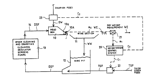
Figure I is a schematic illustration, mainly as a block diagram, of the system
of
regulation in accordance with the invention and its connection with the paper
machine
and its stock feed system;
Figure 2 is a schematic illustration in part of Fig. 1, being a more detailed
illustration
of a Frst embodiment of the invention;
Figure 3 is a schematic illustration in part of Fig. l, being a more detailed
illustration
of a second embodiment of the invention; and
Figure 4 is a schematic illustration of a third exemplifying embodiment of the
invention.
Detailed description of the preferred embodiments
Referring to Figs. 1-4 wherein like reference numerals refer to the same or
similar
elements, Fig. 1 is a schematic illustration of the system of regulation in
accordance
with the present invention and its connection with the paper machine and its
stock
feed system. The paper machine comprises a headbox 10 including a slice duct
l0a
having a slice opening l0A from which a stock suspension jet J is fed onto a
wire in
the wire part 11 of the paper machine. In the paper machine, the wire part 11
is
followed by the press section and the dryer section (not shown). The ready
dried
paper web WE runs past a basis weight measurement device 21 which measures its
basis weight. This measurement may take place after the web has been dried to
its
final basis weight after the dryer section. From the basis weight measurement
device
21, a measurement signal m~ for the cross-direction basis weight profile of
the web
WE is obtained, which signal can, if necessary and/or desired, be passed to
the
regulation system of the height profile of the slice opening 10A of the
headbox 10.
The result of measurement of the cross-direction basis weight profile obtained
from
the measurement device 21 may be processed by computational means to produce
an
average value, and hereby the measurement signal m ~ of the machine-direction
CA 02282751 1999-09-O1
WO 98141685 PCT/FI98/00200
8
profile is obtained. This signal m~ is passed to a system 20 of regulation of
the
machine-direction basis weight. From the regulation system 20, the regulation
signal
c~ is obtained (i.e., the average value of the basis weight determines the
regulation
signal) and used to control a basis weight valve 22 of the thick stock flow
TSF.
Instead of regulating the basis weight valve 22 by means of the signal c~, it
is also
possible to regulate the speed of rotation of the pump (not shown) that feeds
the thick
stock flow TSF. The thick stock flow TSF, whose quantity has been regulated by
means of the valve 22, is fed into a wire pit 12 of the short circulation in
the paper
machine, into which wire pit the wire water flow WW drained from the paper web
in the wire part 11 is passed. In the wire pit 12, the thick stock flow TSF
and the
wire water flow WW are mixed together. From the wire pit 12, a diluted stock
flow
DSF departs, which is passed through a stock cleaning and deaeration unit 13
and
through a stock pipe 14 into the inlet header of the headbox 10.
As shown in Fig. 1, in the manner known from the prior art, regulated dilution
water
flows DW are passed into the headbox 10 into separate flow points in the cross
direction of the headbox. By means of the flows DW, the cross-direction basis
weight
profile of the stock suspension jet J is controlled, possibly together with
regulation of
the cross-direction profile of the slice opening l0A of the headbox 10
(possibly in
association with measurement signal m~) or, preferably, without this
regulation, in
which case a favorable slice opening l0A of uniform height is used.
According to the present invention, the regulation of the machine-direction
basis
weight profile in the paper machine is accomplished in the manner shown in
Fig. 1
by passing a regulation signal c., from the basis weight regulation unit 20 to
an
appropriate actuator 23 which regulates the diluting flows DW. More
specifically, by
means of the actuator 23, the level of the quantity of the dilution flow DW
passing
into the headbox 10 may be changed across the entire width of the headbox 10
and
the web WE. The regulation signal c2 is generated based on the measured basis
weight of the web, for example, as represented by the first measurement signal
from
the .measurement device 21, although it may be based on a measurement of the
basis
weight obtained in a different manner possibly by a different measuring unit.
..._. .._. ._.. . . _ . . . ._. r ~ ,
CA 02282751 1999-09-O1
WO 98/41685 PCT/FI98/00200
9
Figs. 2 and 3 are more detailed illustrations in part of Fig. 1, and are block
diagrams
illustrating two preferred embodiments of the invention.
In Fig. 2, the feedback part of the regulation system is denoted by FB and the
feedforward part of the regulation system is denoted by FF. In the feedback
regulati-
on circuit FB, rapid regulation of the consistency of the stock flow DSF fed
into the
headbox 10 (which constitutes a mixture of the thick stock flow 'fSF and the
wire
water flow WW) is carried out by means of separate dilution at the mixing
point 15a,
to which point, in view of regulation of the overall consistency of the stock
flow fed
into the hcadbox 10, a dilution flow DWT is fed, which flow is regulated by
means
of the actuator 24a. This actuator 24a is regulated by means of a feedback
regulation
signal cc, which is formed based on the signal cm of measurement of the
consistency
of the regulated stock flow DSFC after the mixing point 1 Sa. The actuator 24a
is, for
example, a valve that regulates the dilution flow of the headbox stock or a
corre
sponding regulation pump.
As shown in Fig. 2, the feedforward regulation circuit FF includes measurement
devices 27a, by whose means the consistency of the short circulation of the
main
stock flow of the headbox is measured before the mixing point I Sa
(represented by
the notation mt~, whereby the regulation is made quicker. A regulation signal
cf is
generated by the measurement devices 27a and utilized to regulate the actuator
24a
either alone, if the feedback circuit is not present, or in conjunction with
the regulati-
on of the actuator 24a determined by the feedback regulation signal cc.
The feedback regulation circuit FB and the feedforward regulation circuit FF,
which
are shown in Fig. 2, can be used either separately or together as a
combination in
view of obtaining an optimal regulation result.
The regulation circuit shown in Fig. 3 has an embodiment in other respects
similar to
that described above in relation to Figs. I and 2 except that, instead of or
in addition
to the regulation of the consistency of the headbox stock, the consistency of
the
dilution water flow DW used for cross-direction consistency profiling in the
headbox
CA 02282751 1999-09-O1
WO 98/41b85 PCT/FI98/00200
is regulated by means of a feedback regulation circuit FB andlor by means of a
feedforward regulation circuit FF. In this system of dilution of the dilution
water flow
DW, as the dilution water it is possible to use clear filtrate or any other
water that
does not contain solid matter.
S
As shown in Fig. 3, the feedback regulation circuit FB includes an actuator
28, which
is, for example, an actuator 28 which is used for dilution of the dilution
water flow
DW, i.e., an actuator that regulates the flow DWC used for regulation of the
consis-
tency, for example a pump or a valve. There is thus not only the principal
diluting
10 flow DW being passed to the headbox but also a secondary diluting flow DWC
being
passed into the principal diluting flow DW. In connection with the actuator
28, a
regulator 24b is arranged and receives a regulation signal em from the
measurement
detectors of the consistency of the mixed dilution flow DW after the mixing
point
15b at which the diluting flows DW and DWC are combined. The regulator 24b
passes the regulation signal cd to the actuator 28, and in this manner, a
feedback
regulation circuit FB for the flow DW consistency is formed.
The feedforward regulation circuit FF shown in Fig. 3 includes a regulator
27b,
which receives a measurement signal mf from an earlier stage in the dilution
system
before the mixing point 1 Sb so as to make the regulation quicker. From the
regulator
27b, a regulation signal cf is passed to an actuator 28, which operates as an
actuator
both in the feedforward regulation circuit FF and in the feedback regulation
circuit
FB. The feedforward regulation circuit FF and the feedback regulation circuit
FB can
be used either independently of one another or together as a combination.
In the exemplifying embodiment shown in Fig. 4, the consistency of the stock
flow
DSF (the combination of the thick stock flow TSF and the wire water flow WW)
entering into the headbox 10 is measured by appropriate measuring means which
generate a measurement signal cm. The measurement signal cm thus obtained is
passed to the regulation unit 26a. Further, the consistency of the dilution
water flow
DW is measured by appropriate measuring means, and the measurement signal cdm
thus obtained is passed to the regulation unit 23a. From the units 23a and
26a,
~ ~ . ... .
CA 02282751 1999-09-O1
WO 98141685 PCT/F198/00200
11
regulation signals are passed to a summing/difference member 28. to which the
regulation signal c' described above is also passed, which signal is received
from the
basis weight regulation unit 20. From the member 28, the regulation signal cdc
is
obtained, which is passed to the actuator 23 that regulates the quantity of
the dilution
flow DW. By means of the regulation circuit described above, any disturbance
that
may occur in the consistency of the stock flow DSF is compensated for by
changing
the dilution flow DW.
The principle of operation of the regulation circuit illustrated in Fig. 4 is
substantially
the same as that of the circuit illustrated in Fig. 2, but in the regulation
circuit shown
in Fig. 4, a separate mixing point 1 ~a placed in the approach pipe 14 is not
used, but
the consistency after the dilution stage is affected directly in the headbox.
Since
measurement of the overall consistency from the slice duct is very difficult
in
practice, the regulation circuit shown in Fig. 4 operates with the FF
principle.
Of the regulation circuit illustrated in Fig. 4, such a variation is also
applicable in
which the signal cdm of measurement of the consistency of the dilution flow DW
is
produced from the dilution flow DW after the actuator 23. By means of the
measure-
ment signal cdm, additional information is obtained for predicting the
consistency in
the slice duct of the headbox 10 by means of the FB or FF principle.
It should be noticed in particular that a permanent change in the basis weight
is not
achieved by means of a change in the dilution quantity alone. This comes from
the
fact that, in a state of equilibrium, the quantity of dry solids (dry weight]
that remains
in the paper web WE depends exclusively on the quantity of solid matter that
is fed
into the wire pit 12, i.e., in a state of equilibrium the same quantity of
solid matter
departs along with the paper web W as is fed through the thick stock line into
the
wire pit 12. Thus, it is possible to change the basis weight of the web WE per-
manently exclusively by changing the flow rate or the consistency of the thick
stock.
The mode of regulation in accordance with the present invention can, however,
be
utilized so that the dilution quantity and the feed of thick stock are
controlled at the
CA 02282751 1999-09-O1
WO 98/41685 PCTIFI98/00200
12
same time so that an optimal result of regulation, i.e., the quickest response
in
relation to the basis weight, is achieved.
The examples provided above are not meant to be exclusive. Many other
variations
of the present invention would be obvious to those skilled in the art, and are
contem-
plated to be within the scope of the appended claims.
~.