Note : Les descriptions sont présentées dans la langue officielle dans laquelle elles ont été soumises.
CA 02290919 1999-11-29
1 PUSHER ROLLER ASSF.1VIBi.Y FOR A CAR WASH CONVEYOR
2
3
4 Back~round of the Invention
This invention concerns automotive car wash conveyors, and more
6 particularly pusher roller assemblies used in three track type conveyors.
7 Automatic car washes use conveyors for pulling each car along a track
8 extending through an array of car washing equipment disposed along the
conveyor.
9 One design which has been widely adopted uses a series of roller
assemblies attached to an endless recirculated chain extending around a three
track
11 structure extending the length of the conveyor.
12 The roller assemblies move forwardly down an intermediate track and
13 return on a lower track, the chain circulating along both tracks. When a
car advances
14 onto the upper track and a pusher roller assembly is needed, a forked ramp
is raised from
the intermediate track to intercept and guide an upper pusher roller set of
the roller
16 assembly onto an upper slotted track along which the car tires roll. An
elongated roller
7 bar has the pusher roller set mounted thereon and extends down through the
slot to the
S chain. A set of idler rollers are mounted to the other end of the dog to
provide rolling
'a suppart for the chain and roller assemblies on the intermediate and lower
return tracks.
'.) The pusher roller set rolls along the upper track and also engages the car
1 tire. Two pusher roller pairs are provided, one for engaging the car tire
and the other for
? engaging the upper track.
CA 02290919 1999-11-29
1 In early versions of this design, the tire engaging and track engaging
2 rollers were provided by stepped diameters of a common roller as seen in Re
30,026
3 reissued on June 12, 1979 for a "Vehicle Conveyor".
4 Due to problems with wide tires, the pusher roller sets are now typically
provided with separately tnounted pairs of rollers, each roller of the pairs
cantilevered out
6 from one side of the dog, so that six separate rollers are included in each
roller assembly.
7 An example of this arrangement is shown in U.S. patents 4,873,929 issued
8 on October 17, 1989 for a "Pusher Unit" 4,314,496 issued on February 22,
1983 for a
9 "Vehicle Conveyor", and 4,930,424 issued on June 5, 1990 for a "Conveyor
Chain
Guide".
11 An improved design for the separately mounted pusher rollers is described
12 in U.S. patent 4,864,936 issued on September 12, 1989 to the assignee of
the present
13 application, which design has proved to have provided a long wear life
roller assembly.
14 In these prior conveyors, the rollers are constructed of a durable molded
plastic such as urethane, and are mounted on shafts cantilevered out from each
side of the
16 roller bar. The ends of the rollers are hollowed out to enclose the heads
of bolts used to
17 hold the rollers in place. This arrangement has created a tendency for the
rollers to
18 "grow" in length due to the pressure of the engagement on the unconfined
outer end of
19 the roller. The rollers may jam between the track sides as a result of
their increased
length.
21 The upper pusher rollers are of smaller diameter than the lower idler
22 rollers, and one roller pair in the pusher set runs along all three tracks.
2
CA 02290919 2007-03-15
I Pue to the small diameter of those rollers, early wearout of the pusher
2 rollers has been a problem, which is a major maintenance burden, as
replacement often
3 requires disassembly of the chain and roller assemblies. One set of rollers
is used to
4 engage the forked ramp, and if excessive wear of that roller set has
occurred, proper
engagement with the ramp may not be possible, rendering that roller assembly
6 inoperative. This is a particular problem where "coning" wear of the roller
creates a
7 tendency for the rollers to track to one side in ascending the fork ramp. As
the rollers are
8 typically not replaced until complete wearout has occurred, further
maintenance often
9 must be done as a result of roller wearout.
The construction of the prior art roller assemblies has also led to high
11 manufacturing costs, and also misalignments of the rollers in each pair is
common.
12 Applicant has heretofore also sold roller assemblies using three pairs of
13 pusher rollers in attempt to reduce wear, but this design involved two sets
of rollers
14 rolling on the upper track when not engaged such that no real wear
reduction resulted.
Accordingly, it is an object of the present invention to provide a pusher
16 roller assembly of the type described in which the frequency of roller
replacement
17 required as a result of roller wear is reduced.
i s It is another object of the present invention is to provide such a pusher
19 roller assembly which may be manufactured at low cost and insures good
alignment of
the rollers in each pair.
21
3
CA 02290919 1999-11-29
1 summaIyQf the Invention
2 The above objects of the invention as well as other objects which will
3 become apparent upon a reading of the following specification and claims are
achieved
4 by having three roller pairs mounted to the upper end of a roller bar which
also has a
larger diameter idler rolfer mounted to the lower end in conventional fashion.
6 The three roller pairs have their rotational axes arranged in a triangular
7 pattern, located so that each roller pair separately rides on a respective
one of the upper,
8 intermediate, and lower return tracks so as to provide a three way sharing
of the pusher
9 wear roller caused by running along the three track levels. This
substantially extends the
wear life of all of the upper pusher rollers, and makes the wear of each
roller more
11 uniform. In particular, the wear of the roller pair engaging the forked
ramp is minimized,
12 such that reliable engagement is achieved over an extended service life.
13 The upper pusher roller set is of welded construction, comprised of four
14 identical end plates, arranged in spaced apart pairs on either side of the
upper end of the
roller bar. Three identical shafts extend through aligned holes in each of the
four end
16 plates. Six identical rollers are rotatably mounted in properly aligned
pairs on the
17 respective shafts, located intermediate the end plates. The rollers are not
counterbored
18 and are confined at their ends to positively prevent any increase in length
during service.
19 The end plates are welded to each of the shafts, and two of the shafts are
welded to the roller bar upper end to secure the upper roller assembly to the
roller bar,
21 providing a low cost yet precision construction, allowing economic
replacement of the
22 entire roller assembly rather than replacement of the individual rollers.
4.
CA 02290919 1999-11-29
,-_
1 The overall depth of the pusher roller assembly is preferably limited to
2 allow use on existing conveyor track ways designed for the prior two roller
pusher sets.
3
4 Description of the Drawings
Figure 1 is a=perspective view of the pusher roller assembly according to
6 the invention.
7 Figure 1A is an enlarged perspective view of the pusher roller shown in
8 Figure 1 in a reversed position.
9 Figure 1B is an enlarged end view of the pusher roller assembly.
Figure 2 is an exploded perspective view of the components of the roller
11 assembly shown in Figures 1 and IA.
12 Figure 3 is a simplified side elevational view of the roller assembly in
the
13 various operative portions assumed on the conveyor tracks, a portion of the
tracks and
14 vehicle tire shown diagramatically.
Figure 4 is a fragmentary side view of a conveyor using the roller
16 assembly of the present invention.
17 Figure 5 is an end view of the conveyor track structure.
18
19 Detailed Descritp ion
In the following detailed description, certain specific terminology will be
21 employed for the sake of clarity and a particular embodiment described in
accordance
22 with the requirements of 35 USC 112, but it is to be understood that the
same is not
5
CA 02290919 2007-03-15
I intended to be limiting and :-hould not be so construed inasmuch as the
invention is
2 capable of taking many forms and variations within the scope of the appended
claims.
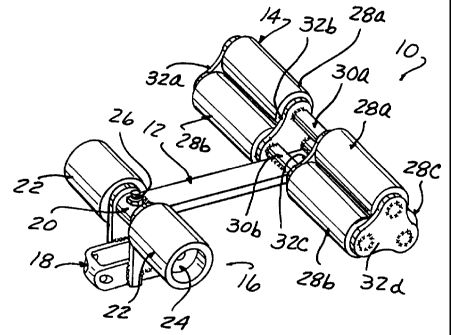
3 Referring to Figures 1 and 2, the conveyor roller assembly 10 according to
4 the present invention includes an elongated roller bar 12, sometimes also
referred to as a
dog having a pusher roller set 14 -mounted to its upper end, and an idler
roller set 16
6 mounted to its lower end.
7 The lower end of the roller bar 12 has a chain connector 18 comprised of
8 U-piece 18A and side plates 18B rotatably supported on a shaft 19 received
in a sleeve 20
9 welded to the lower end of the roller bar 12. A pair of large diameter
urethane idler
rollers 22 are rotatably supported on the shaft 19, retained with a bolt and
washer set 24, a
11 cross bolt 26 preventing rotation of the shaft 19 in the sleeve 20.
12 The idler roller set 16 is of conventional design, and is well known to
13 those skilled in the art.
14 The pusher roller set 14 comprises three parallel pairs of straight sided
molded urethane rollers 28A, 28B, 28C having their rotational axes arranged in
an
16 equilateral triangular pattern. Each roller in the pairs 28A, 28B, 28C are
supported on a
17 respective side of the upper end of the dog 12. The rotational axes are
defined by three
18 identical shafts 30A, 30B, 30C, two of the shafts 30B, 30C overlying and
welded
19 extending across the upper end of the roller bar 12 and welded thereto.
- The pusher rollers 28A, 28B, 28C are individually confined by four
21 identical aligned plates 32A, 32B, 32C, 32D, each of generally triangular
shape and
22 having three holes 34 formed therein to receive a respective axle shaft
30A, 30B, 30C.
6
CA 02290919 1999-11-29
1 Welds around each hole 34 fix the plates 32A-D to the shafts 30A-C.
2 Referring to Figures 3 and 4, a representation of the several positions
3 assumed by the roller assembly 10 in traversing the conveyor tracks is
illustrated. The
4 roller assembly 10 is contemplated for use with a conventional car wash
conveyor of the
well known type, and herice a detailed description is not here set forth.
6 Suffice it to say, that such conveyors have a multilevel track frame F
7 providing three track levels, an upper track 38 on which the car tires T
roll when engaged
8 by the pusher roller set 14, an intermediate track 40 which receives the
roller assemblies
9 10 when the pusher sets 14 are not ramped up to upper track 38; and a lower
or return
track 42 down which the roller assemblies 10 pass in being returned to the
forward end of
11 the conveyor (see also Figure 5).
12 The roller assemblies 10 are connected to an endless chain 44 circulating
13 along the intermediate and lower tracks 40, 42 passing around sprockets SI,
S2 at either
14 end of the conveyor. When a roller assembly 10 is to be activated, a
pivoting ramp R is
i 5 swung up engaging roller pairs 28A to cause a pusher roller set 14 to be
cammed up from
6 the idle position "A" to the upper track 38, where it assumes the activated
but unengaged
7 position "B". Upon engaging a vehicle tire T, the idler rollers 22 are
pulled up against
S the undersurface of upper track 38 to assume position "C", causing the
roller bar 12 to be
9 more inclined due to the resistance created by the tire T. Typically,
several unengaged
0 roller assemblies 10 are caused to be swung up behind an engaged roller
assembly 10 as a
I safety measure. Thus, each roller assembly 10 will have a substantial period
of use
.2 traversing the upper track 38 while not engaging a vehicle tire T.
7
CA 02290919 2007-03-15
I At the end of the conveyor, the roller assemblies 10 proceed back along
2 the lowest track 42 in a reverse position "D".
3 According to the present invention, the pusher roller set comprises three
4 pairs of rollers 28A-C rather than two, and these pusher roller sets are
each arranged to
respectively engage oneof the tracks 38, 40, 42 to more uniformly distribute
the wear.
6 The pusher roller set pairs 28A-C are arranged so that each one of the pairs
7 engages a respective one of the tracks 38, 40, 42 when the roller assembly
10 is not in
8 engagement with a vehicle tire T.
9 That is, roller pair 28B runs an upper track 38, roller pair 28A runs on
intermediate track 40, and roller pair 28C runs on lower return track 42.
11 When a tire T is engaged, a more pronounced backward tilting of the dog
12 12 brings roller pair 28A into engagement with the upper track 38 and
roller pair 28C
13 engages the tire T.
14 This result is produced by arranging one of the pusher roller pairs 28C, to
protrude forwardly of the front face of the roller bar 12, while a second
roller pair 28B is
16 disposed below and slightly recessed behind the front surface of the roller
bar 12, and the
17 third 28A is located well behind both directly to the rear of the roller
bar 12.
18 Thus, when the assembly 10 is inclined slightly to the rear from the
19 vertical (position "B") roller pair 28B engages track 38. When the roller
assembly 10 is
lying completely over to the right (position "A") the rearnlost roller pair
28A engages
21 intermediate track 40.
8
CA 02290919 1999-11-29
I When the roller assembly is lving completely over to the left (position
2 "D"), roller pair 28C engages lower return track 42.
3 Finally, when a tire T is engaged and the roller assembly is tilted more to
4 the rear (position "C"), roller pair 28C engages the tire T and roller pair
28A engages the
upper track 38.
6 Thus, a more uniform wear of the pusher rollers results, and a reduced rate
7 of wear of all three pusher rollers is achieved, to reduce maintenance. In
particular, the
8 ramp engaging roller pair 28B will have much reduced wear, making the proper
9 engagement therewith much more likely. The solid construction of the pusher
rollers
minimizes axial growth and coning wear patterns.
11 As seen in Figure 1B, the overall dimension "A" across roller pairs 28A
12 and 28C, and across roller pairs 28B and 28C is preferably around 3.69
inches so as to fit
13 existing conveyors and this allow the roller assemblies 10 to replace prior
art roller
14 assemblies without modification.
9