Sélection de la langue

Search

Sommaire du brevet 2292006 

Énoncé de désistement de responsabilité concernant l'information provenant de tiers

Une partie des informations de ce site Web a été fournie par des sources externes. Le gouvernement du Canada n'assume aucune responsabilité concernant la précision, l'actualité ou la fiabilité des informations fournies par les sources externes. Les utilisateurs qui désirent employer cette information devraient consulter directement la source des informations. Le contenu fourni par les sources externes n'est pas assujetti aux exigences sur les langues officielles, la protection des renseignements personnels et l'accessibilité.

Disponibilité de l'Abrégé et des Revendications

L'apparition de différences dans le texte et l'image des Revendications et de l'Abrégé dépend du moment auquel le document est publié. Les textes des Revendications et de l'Abrégé sont affichés :

  • lorsque la demande peut être examinée par le public;
  • lorsque le brevet est émis (délivrance).
(12) Brevet: (11) CA 2292006
(54) Titre français: MEMBRANE A RENFORT MODIFIE
(54) Titre anglais: DIAPHRAGM WITH MODIFIED INSERT
Statut: Réputé périmé
Données bibliographiques
(51) Classification internationale des brevets (CIB):
  • F16K 7/12 (2006.01)
  • B60T 15/36 (2006.01)
  • F16J 3/02 (2006.01)
(72) Inventeurs :
  • STREITMAN, LAWRENCE R. (Etats-Unis d'Amérique)
(73) Titulaires :
  • WESTINGHOUSE AIR BRAKE COMPANY (Etats-Unis d'Amérique)
(71) Demandeurs :
  • WESTINGHOUSE AIR BRAKE COMPANY (Etats-Unis d'Amérique)
(74) Agent: MACRAE & CO.
(74) Co-agent:
(45) Délivré: 2003-02-11
(22) Date de dépôt: 1999-12-09
(41) Mise à la disponibilité du public: 2000-07-13
Requête d'examen: 1999-12-09
Licence disponible: S.O.
(25) Langue des documents déposés: Anglais

Traité de coopération en matière de brevets (PCT): Non

(30) Données de priorité de la demande:
Numéro de la demande Pays / territoire Date
229,429 Etats-Unis d'Amérique 1999-01-13

Abrégés

Abrégé anglais


The present invention provides a diaphragm member for use
in certain valve assemblies. Such diaphragm member comprises a
generally circular diaphragm having a first predetermined
diameter and having a first surface and a second surface. Such
generally circular diaphragm is formed from at least one layer
of a preselected elastomeric material. Such generally circular
diaphragm includes a nonflexing center portion, a generally
annular flexure portion extending around an outer periphery of
such nonflexing center portion and a non flexing outer portion
extending around an outer periphery of such generally annular
flexure portion, such non flexing outer portion is engageable
with a body portion of such valve assembly. Such diaphragm
member further includes a generally circular insert member,
having a second predetermined diameter, disposed within said
first surface of such nonflexing center portion of such
generally circular diaphragm. Such generally circular insert
member has a plurality of apertures formed through such
generally circular insert member, such plurality of apertures
provide a predetermined open area for receiving a predetermined
rubber compound for bonding such generally circular insert
member to such nonflexing center portion of such generally
circular diaphragm.

Revendications

Note : Les revendications sont présentées dans la langue officielle dans laquelle elles ont été soumises.


I claim:
1. A diaphragm member for use in certain valve
assemblies, said diaphragm member comprising:
(a) a generally circular diaphragm having a first
predetermined diameter and having a first surface and a second
surface, said generally circular diaphragm formed from at least
one layer of a preselected elastomeric material, said generally
circular diaphragm including:
(i) a nonflexing center portion ,
(ii) a generally annular flexure portion extending
around an outer periphery of said nonflexing center
portion, and
(iii) an outer portion extending around an outer
periphery of said generally annular flexure portion engageable
with a body portion of such valve assembly; and
(b) a generally circular, nonflexible insert member,
having a second predetermined diameter, disposed within said
first surface of said nonflexing center portion of said
generally circular diaphragm, said generally circular insert
member having a plurality of apertures formed through said
generally circular insert member, said plurality of apertures
providing a predetermined open area for receiving a preselected
elastomeric material for bonding said generally circular,
nonflexing insert member to said nonflexing center portion of
said generally circular diaphragm.


8


2. A diaphragm member for use in certain valve
assemblies, according to claim 1, wherein said plurality of
apertures on said generally circular insert being disposed
closely adjacent an outer periphery.
3. A diaphragm member for use in certain valve
assemblies, according to claim 1, wherein said plurality of
apertures on said generally circular insert being disposed on
an axis that is concentric to said outer periphery.
4. A diaphragm member for use in certain valve
assemblies, according to claim 3, wherein said plurality of
apertures on said generally circular insert being spaced
generally equidistant from each other.
5. A diaphragm member for use in certain valve
assemblies, according to claim 1, wherein said plurality of
apertures in said generally circular insert is four.
6. A diaphragm member for use in certain valve
assemblies, according to claim 1, wherein said generally
circular insert is molded within said diaphragm.
7. A diaphragm member for use in certain valve
assemblies, according to claim 1, wherein said generally
circular insert is one of a metal and a metallic alloy.


9


8. A diaphragm member for use in certain valve
assemblies, according to claim 7, wherein said generally
circular insert is
brass.
9. A diaphragm member for use in certain valve
assemblies, according to claim 1, wherein said preselected
elastomeric material is selected from rubber, synthetic rubber
and plastics.
10. A diaphragm member for use in certain valve
assemblies, according to claim 9, wherein said preselected
elastomeric material further includes fabric reinforcement.
11. A diaphragm member for use in certain valve
assemblies, according to claim 10, wherein said fabric
reinforcement is nylon.


10
Description

Note : Les descriptions sont présentées dans la langue officielle dans laquelle elles ont été soumises.


CA 02292006 1999-12-09
DIAPHRAGM WITH MODIFIED INSERT
FIELD OF THE INVENTION
The present invention relates, in general, to diaphragm
used in valves and, more particularly, the present invention
relates to a diaphragm with a modified insert for use in
limiting valves in railway control valves.
BACKGROUND OF THE INVENTION
Control valves are an integral part of most railway freight
cars. The control valve operates to control the flow of air to
and from the brake cylinders and to charge the auxiliary and
emergency reservoirs. An important part of such control valves
are limiting valves.
The service portion of such control valves contains two
brake cylinder limiting valves which function to limit the
maximum pressure directed to the brake cylinder application pipe
or brake cylinder relay valve control pipe during service or
emergency brake applications. The limiting valves are
designated as the "Service Limiting Valve" and the "Emergency
Limiting Valve". The maximum pressure output from these
limiting valves is predetermined by load settings on the springs
within each valve.
Such limiting valves rely on diaphragms to perform their
function. A metal insert is mounted on such diaphragms and is
held in place by the use of an adhesive. One problem with the
present technology is that the diaphragm tends to delaminate at
the periphery of the metallic insert because this is a stress
1

CA 02292006 1999-12-09
concentration point which leads to delamination as the diaphragm
flexes during operation. When delamination occurs, the
diaphragm becomes inoperable and must be replaced before the
control valve can operate properly again. Occurrences of this
type are considered premature failure of the diaphragm and
result in down time and further expense for the railroad. Thus,
any improvement to the diaphragm that will eliminate premature
failure and extend the useful service life of the diaphragm is
desirable.
SUMMARY OF THE INVENTION
The present invention provides a diaphragm member for use
in certain valve assemblies. Such diaphragm member comprises a
generally circular diaphragm having a first predetermined
diameter and having a first surface and a second surface. Such
generally circular diaphragm is formed from at least one layer
of a preselected elastomeric material. Such generally circular
diaphragm includes a nonflexing center portion, a generally
annular flexure portion extending around an outer periphery of
such nonflexing center portion and a non flexing outer portion
extending around an outer periphery of such generally annular
flexure portion, such non flexing outer portion is engageable
with a body portion of such valve assembly. Such diaphragm
member further includes a generally circular insert member,
having a second predetermined diameter, disposed within said
first surface of such nonflexing center portion of such
generally circular diaphragm. Such generally circular insert
2

CA 02292006 1999-12-09
member has a plurality of apertures formed through such
generally circular insert member, such plurality of apertures
provide a predetermined open area for receiving a predetermined
rubber compound for bonding such generally circular insert
member to such nonflexing center portion of such generally
circular diaphragm.
OBJECTS OF THE INVENTION
Therefore, it is one of the primary objects of the present
invention to provide a diaphragm for such limiting valves that
will have longer service life.
It is an additional object of the present invention to
provide a diaphragm that will not delaminate.
Another object of the present invention is to provide a
diaphragm in which the insert is molded to the diaphragm.
Still, another object of the present invention is to
provide an insert for such diaphragm that will permit such
insert to be molded and retained in such diaphragm.
Yet another object of the present invention is to modify
the profile of the diaphragm so as to reduce stress points on
the diaphragm.
In addition to the numerous objects and advantages of the
present invention which have been described with some degree of
particularity above, it should be both noted and understood that
a number of other important objects and advantages of the
diaphragm with a modified insert will become more readily
apparent to those persons who are skilled in the relevant
3


CA 02292006 1999-12-09
diaphragm art from the following more detailed description of
the invention, particularly, when such detailed description is
taken in conjunction with the attached drawing Figures and with
the appended claims.
BRIEF DESCRIPTION OF THE DRAWINGS
Figure 1 is a plan view of a prior art diaphragm with an
insert.
Figure 2 is a cross-sectional view taken across the line
II-II of the prior art diaphragm with an insert shown in Figure
1.
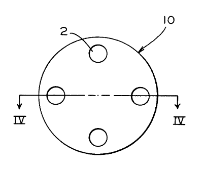
Figure 3 is a plan view of a modified insert in an
embodiment of the invention.
Figure 4 is a cross-sectional view of the insert shown in
Figure 3 taken across the lines of IV-IV.
Figure 5 is a cross-sectional view of the diaphragm with a
modified insert in an embodiment of the invention.
Figure 6 is a cross-sectional view of the diaphragm with a
modified insert of the present invention shown in a limiting
valve.
BRIEF DESCRIPTION OF THE PRESENTLY
PREFERRED AND VARIOUS ALTERNATE
EMBODIMENTS OF THE INVENTION
Prior to proceeding to the more detailed description of the
various embodiments of the invention, it should be noted that,
for both the sake of clarity and understanding of the improved
resilient type sealing member according to the present
invention, identical components which have identical functions
4


CA 02292006 1999-12-09
have been identified with identical reference numerals
throughout the several views which have been illustrated in the
attached drawing Figures.
Reference is now made to Figures 1 and 2. Illustrated
therein is a prior art diaphragm with an insert as is presently
used in the industry.
Reference is now made to Figures 3, 4 and 5. Illustrated
therein are various views of such modified generally circular
insert, generally designated 10. Also shown is such diaphragm
member, generally designated 20, with such modified generally
circular insert 10 disposed therein.
As is evident, insert 10 has a plurality of apertures 2
formed through such insert 10. In a presently preferred
embodiment of the invention such plurality of apertures 2 is
four. Also in the presently preferred embodiment of the
invention such apertures are all positioned near the outer
periphery of such generally circular insert 10. Two of such
apertures are placed on a horizontal axis of such generally
circular insert 10, while the other two apertures 2 in the
presently preferred embodiment are placed on the longitudinal
axis, near the outer periphery of such insert 10. Such
apertures are placed generally equidistant from such outer
periphery.
The generally circular insert 10 can be seen disposed
within diaphragm 4 to form the complete diaphragm member 20 in
Drawing Figure 5. Evident in Figure 5 is also a profile change


CA 02292006 1999-12-09
6 made in such diaphragm 4 where the diaphragm meets such insert
10. In prior art diaphragms this is the stress concentration
point which led to delamination where the rubber diaphragm
bonded to the insert edge. Such profile change 6 permits the
rubber to be bonded up to the top of the insert 10 thereby
reducing stress concentration at the edge of insert 10 during
flex cycling in application of the valve. The flexure portion
of such diaphragm member 20 is the portion between such profile
change 6 and the outer periphery 14 which is secured by the body
of a valve.
The modification in insert 10 permits insert 10 to be
registered in the molding process to allow for producing the
profile change 6. In the preferred embodiment of the invention
such insert would be molded directly into diaphragm 4 to form
such diaphragm member 20.
Although not limited to such use, the present invention has
been designed for use in the limiting valve portion of service
control valves on railway rolling stock. Figure 6 shows the
application of such diaphragm member 20 in one such limiting
valve. Such limiting valve stem 8 passes through the valve
bushing 11 to contact the generally circular insert 10 of
diaphragm 20 to push on diaphragm follower 13. The outer
periphery 14 of such diaphragm member 20 is secured by body
portions of such limiting valve. Valve stem 8 pushes on
diaphragm 20 causing it to move downward until the preload of
the spring causes such diaphragm follower 13 to push back
6

CA 02292006 1999-12-09
upward. This flexing of flexure portion of such diaphragm 20
places considerable strain on the portion of the diaphragm that
abuts the generally circular insert 10. It is this place that
premature delamination in prior art diaphragms occured. With
the present invention, not only is the generally circular insert
more firmly embedded in the diaphragm to be betterable to absorb
the stress forces but the profile change 6 reduces such stress
concentration even more and thus the service life of such
diaphragm 20 is extended considerably.
While a presently preferred and an alternative embodiment
of the present invention have been described in detail above, it
should be understood that various other adaptations and/or
modifications of the present invention can be made by those
persons who are particularly skilled in the art related to
diaphragms and, more particularly, diaphragms used in such valve
systems without departing from either the spirit of the
invention or the scope of the appended claims.
7

Dessin représentatif
Une figure unique qui représente un dessin illustrant l'invention.
États administratifs

Pour une meilleure compréhension de l'état de la demande ou brevet qui figure sur cette page, la rubrique Mise en garde , et les descriptions de Brevet , États administratifs , Taxes périodiques et Historique des paiements devraient être consultées.

États administratifs

Titre Date
Date de délivrance prévu 2003-02-11
(22) Dépôt 1999-12-09
Requête d'examen 1999-12-09
(41) Mise à la disponibilité du public 2000-07-13
(45) Délivré 2003-02-11
Réputé périmé 2004-12-09

Historique d'abandonnement

Il n'y a pas d'historique d'abandonnement

Historique des paiements

Type de taxes Anniversaire Échéance Montant payé Date payée
Requête d'examen 400,00 $ 1999-12-09
Enregistrement de documents 100,00 $ 1999-12-09
Le dépôt d'une demande de brevet 300,00 $ 1999-12-09
Taxe de maintien en état - Demande - nouvelle loi 2 2001-12-10 100,00 $ 2001-11-23
Taxe finale 300,00 $ 2002-10-31
Taxe de maintien en état - Demande - nouvelle loi 3 2002-12-09 100,00 $ 2002-11-29
Titulaires au dossier

Les titulaires actuels et antérieures au dossier sont affichés en ordre alphabétique.

Titulaires actuels au dossier
WESTINGHOUSE AIR BRAKE COMPANY
Titulaires antérieures au dossier
STREITMAN, LAWRENCE R.
Les propriétaires antérieurs qui ne figurent pas dans la liste des « Propriétaires au dossier » apparaîtront dans d'autres documents au dossier.
Documents

Pour visionner les fichiers sélectionnés, entrer le code reCAPTCHA :


Pour visualiser une image, cliquer sur un lien dans la colonne description du document. Pour télécharger l'image (les images), cliquer l'une ou plusieurs cases à cocher dans la première colonne et ensuite cliquer sur le bouton "Télécharger sélection en format PDF (archive Zip)" ou le bouton "Télécharger sélection (en un fichier PDF fusionné)".

Liste des documents de brevet publiés et non publiés sur la BDBC .

Si vous avez des difficultés à accéder au contenu, veuillez communiquer avec le Centre de services à la clientèle au 1-866-997-1936, ou envoyer un courriel au Centre de service à la clientèle de l'OPIC.


Description du
Document 
Date
(yyyy-mm-dd) 
Nombre de pages   Taille de l'image (Ko) 
Dessins 1999-12-09 4 94
Abrégé 1999-12-09 1 36
Description 1999-12-09 7 253
Revendications 1999-12-09 3 81
Dessins représentatifs 2003-01-08 1 4
Page couverture 2003-01-08 1 42
Page couverture 2000-07-05 1 40
Dessins représentatifs 2000-07-05 1 3
Dessins 2000-03-02 3 51
Correspondance 2002-10-31 1 36
Poursuite-Amendment 2000-03-02 4 86
Cession 1999-12-09 4 156