Note : Les descriptions sont présentées dans la langue officielle dans laquelle elles ont été soumises.
CA 02296573 2006-03-02
STRUCTURAL MEMBER WITH ALIGNING
MEANS FOR A MATING PART
BACKGROUND OF THE INVENTION
The present invention relates to a structural member with aligning means for a
mating part, and more particularly to a rigid body formed of a hard material
having at
least one hole therein for receiving a mating part formed of a material such
as wood
which is softer than the material of the body. The hole includes alignment
means for
properly aligning the mating part relative to the body.
The invention is especially adapted for use with pieces of wood such as
conventional "2X4 lumber", wherein the lumber has a rectangular cross-section.
The
rigid body may comprise a component of shelving utilizing 2X4 lumber such as
disclosed in U.S. Design Patent No. 419,814. The rigid body may also comprise
a
component of a convertible bench and table top assembly as disclosed in U.S.
Patent
No. 4,913,488. The invention can be employed in other types of construction
wherein it
is desired to interconnect a rigid body with a mating part which is formed of
material
which is softer than that of the rigid body.
The original design of the rigid body for use with shelving is disclosed in
U.S. Design Patent No. 416,424. In this original design, rectangular holes
were
provided which were oversized for receiving pieces of lumber therein which
were
-1-
CA 02296573 2000-O1-20
secured in place by screws. It is common knowledge that lumber, while milled
to a
specific dimensional size, does not maintain its dimensions and shape when
exposed
to the environment, resulting in the lumber swelling, bowing, twisting and
cupping.
The oversized rectangular holes were intended to provide clearance for the
changes in
size and shape of the lumber which occurs in the normal course of events,
without
introducing stress into the rigid body. The rigid body and piece of lumber
were
assembled by the use of a single screw extending through one long side of a
hole and
a single screw extending through one short side of a hole, effectively pulling
the
lumber into contact with the sides of the hole forming one corner of the hole,
which is
similar to the arrangement with other commonly available brackets and the
like.
This original design proved to be unacceptable. Since the rigid body may be,
for example, either a metallic casting or a molded plastic, it is necessary to
provide
relief angles or "draft" for the large rectangular openings so that the molded
or cast
body can be effectively released from the mold. Such relief angles make it
difficult to
properly align the lumber so that it extends perpendicular to the body as is
desired.
Furthermore, the average amount of clearance between most lumber and the sides
of
the holes afforded movement and/or deflection of the non-contacting sides of
the
lumber, which resulted in twisting and misalignment of the rigid body relative
to the
lumber. Therefore, the assembled rigid bodies and lumber are not sufficiently
stable.
This is a common problem with these types of assemblies, and manufacturers
often
suggest the use of additional components for cross-bracing the assemblies.
-2-
CA 02296573 2000-O1-20
SUMMARY OF THE INVENTION
The present invention incorporates one or more holes which are slightly larger
than the nominal dimensions of a piece of lumber to accept the variations in
the
dimensions of the lumber, and the holes in the rigid body are provided with
means for
positively properly aligning a piece of lumber relative to the body so that
the lumber
will be perpendicular to opposite sides of the body.
It is apparent that the invention may be employed with a rigid body having a
single hole therein, or a body having a multiplicity of holes therein. In
either case,
each hole is generally rectangular in cross-section as is the mating part such
as a piece
of 2X4 lumber. The hole has two long sides and two short sides, with a
longitudinal
axis extending through the hole. Three ribs are provided which project into
the hole
and extend generally parallel with the axis of the hole. A first rib is formed
at the
midpoint of the one of the long sides of the hole; and a second rib is formed
at the
midpoint of the other one of the long sides of the hole. A third rib is formed
at the
midpoint of one of the short sides of the hole. In a modified form of the
invention, a
fourth rib is formed at the midpoint of said one of the short sides of the
hole.
The ribs on the rigid body are molded without draft to extend parallel with
the
longitudinal axis of the hole and provide three points of contact with the
mating part,
which, by design, automatically squares the lumber relative to the body. The
body
and mating part are fastened to one another by one or more screws. In the case
of
swollen or twisted lumber, the ribs contact and/or penetrate the softer lumber
at only
the three points of contact, and therefore the rigid body is more easily moved
or
-3-
CA 02296573 2000-O1-20
repositioned relative to a piece of lumber without jamming within the hole
such as
would occur if the hole were a close fitting hole without ribs.
BRIEF DESCRIPTION OF THE DRAWINGS
Figure 1 is a bottom perspective view of shelving utilizing a structural
member
according to the invention;
Figure 2 is an enlarged top view of one of the holes in the structural member;
Figure 3 is top perspective view of the structural member shown in Figure 1;
Figure 4 is a bottom perspective view of the structural member shown in
Figure 3;
Figure 5 is an enlarged sectional view taken on line 5-5 of Figure 3;
Figure 6 is a top perspective view of a modified structural member according
to the invention;
Figure 7 is an enlarged view of a portion of the structure shown in Figure 6;
Figure 8 is an enlarged view of the portion of Figure 7 indicated by arrow 8-
8;
and
Figure 9 is an enlarged section taken along line 9-9 of Figure 6.
DESCRIPTION OF THE PREFERRED EMBODIMENTS
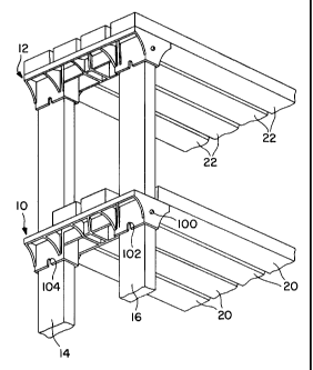
Referring to the drawings wherein like reference characters designate
corresponding parts throughout the several views, a first embodiment is shown
in
Figures 1 - 5 of the drawings. As seen in Figure 1, shelving incorporating the
present
invention is illustrated including a pair of similar structural members
indicated
generally by reference numerals 10 and 12. A pair of vertically extending 2X4
pieces
-4-
CA 02296573 2000-O1-20
of lumber 14 and 16 extend upwardly through two holes (hereinafter described)
formed in member 10 and the top ends of the pieces 14 and 16 are disposed
within
two holes (hereinafter described) formed in member 12. A first plurality of
horizontal
2X4 pieces of lumber 20 are supported by member 10; and a second plurality of
2X4
pieces of lumber 22 are supported by member 12.
As seen in Figures 3 and 4, the details of construction of member 10 can be
seen wherein a rigid body 30 is formed of a hard material. For example, body
30 may
be a one piece metallic casting or molded plastic which is considerably harder
than
the lumber used therewith. The body includes a flat top surface 32 and
downwardly
extending webs and strengthening gussets 34 as well as opposite end faces, one
of
which 36 is visible in Figures 2 and 3. The walls also define a pair of holes
40 and 42
which extend through the body from face 32 to the bottom edge 44 of the body.
Hole 40 includes two long sides 46 and 48, and two short sides SO and 52.
Hole 42 includes two long sides 56 and 58, and two short sides 60 and 62. Long
sides 46 and 48 of hole 40 are symmetrical about a longitudinal axis A-A
extending
through hole 40, and short sides 50 and 52 are also symmetrical about axis A-
A.
Long sides 56 and 58 of hole 42 are symmetrical about a longitudinal axis B-B
extending through hole 42; and the short sides 60 and 62 are also symmetrical
about
axis B-B.
As seen in Figure 2, long side 56 of hole 42 has a lower edge 56' and an upper
edge 56". Long side 58 has a lower edge 58' and an upper edge 58". Short side
60
has a lower edge 60' and an upper edge 60". Short side 62 has a lower edge 62'
and
-5-
CA 02296573 2000-O1-20
an upper edge 62". It is therefore apparent that hole 42 has given dimensions
at the
lower edge of the body and that the hole tapers to a greater dimension at the
upper
surface 32 of the body so that each of the sides of the hole defines draft for
molding
or casting purposes.
A first rib 70 is disposed on long side 56 of hole 42 projects into the hole
and
extends parallel to axis B-B. Therefore, rib 70 has zero draft. A second rib
72 is
disposed on long side 58 of hole 42 and also projects into the hole and
extends
parallel to axis B-B. Therefore, rib 72 has zero draft. A third rib 74 is
disposed on
short side 60 of the hole and projects into the hole and extends parallel to
axis B-B.
Therefore rib 74 has zero draft. Each of the ribs is disposed at the midpoint
of the
associated side of the hole. As seen in Figure 4, a pair of openings 80 and 82
are
provided in the lower edge of the long sides 56 and 58 of hole 42 for a
purpose
hereinafter described. Body portions 80' and 82' extend into hole 42 to
provide
reinforcement adjacent openings 80 and 82. Ribs 70 and 72 join body portions
80
and 82 respectively, as seen in Figures 2 and 4.
Another opening 84 is formed in the body and extends from end face 36 into
communication with hole 42 at short side 60 of the hole. Since opening 84 is
disposed substantially midway between opposite side edges 86 and 88 of the
rigid
body, opening 84 passes through rib 74.
Hole 40 incorporates the same construction as hole 42 and includes a pair of
ribs 90 and 92 disposed on the long sides 46 and 48 respectively of the hole,
and a
third rib 94 is disposed on short side 50 of the hole. The remaining structure
-6-
CA 02296573 2000-O1-20
associated with hole 40 is similar to that described in connection with hole
42, and
need not be described in detail. As seen in Figure 5, an opening 96 similar to
opening
84 is provided through rib 94, and openings 106 and 108 similar to openings 80
and
82 are provided in the lower edges of long sides 46 and 48 of hole 40.
Although rib
94 has a generally semicircular configuration similar to rib 74, rib 94 as
well as rib 74
actually tapers from a smaller lateral dimension from the lower edge 44 of the
rigid
body to the top surface 32 of the body due to the draft of short side of the
associated
hole. Each of ribs 90, 92 and 94 has zero draft.
When pieces of lumber are inserted into holes 40 and 42, a single screw is
inserted through holes 84 and 94 in the end faces of the body and screwed into
the
pieces of lumber to fasten the lumber to the body. If the weight applied to
structural
member 10 in Figure 1 is such that a single screw 100 inserted through opening
84
might fail in shear, additional screws such as 102 and 104 may be inserted
through
openings 80 and 82 to provide additional support for the structural member.
Additional openings such as indicated at 110 in Figure 3 are provided
throughout the upper surface 32 of the rigid body for attaching horizontal
pieces of
lumber 20 to the rigid body as shown in Figure 1.
Referring now to Figures 6 - 9, another embodiment of the invention is
illustrated. A rigid body in the form of a stanchion member 120 is similar to
stanchion member 16 shown in U.S. Patent 4,913,488 for use in a convertible
bench
and table top assembly. This rigid body may be formed of the same material as
the
rigid body 30. Member 120 has a mold or casting parting line 122, a vertical
web 124
CA 02296573 2000-O1-20
being formed throughout the structure along the parting line and extending a
short
distance on either side of the parting line. The structure shown on one side
of the web
as seen in Figure 6 is repeated on the other side of the web so that the
structure on
opposite sides of the web are mirror images of one another.
A first rectangular hole 130 is defined by walls 132 and 134 which form two
long sides of the hole and walls 136 and 138 which define two short sides of
the hole.
Referring to Figures 7 and 9, the face of wall 132 defining a long side of
hole 130
intersects the parting line 122 at line 132', and the face of wall 132 has an
outer edge
at 132". The face of wall 134 defining the other long side of hole 130
intersects the
parting line 122 at line 134', and the face of wall 134 has an outer edge at
134". The
face of wall 136 defining one short side of hole 130 intersects the parting
line 122 at
136', and the face of wall 136 has an outer edge at 136". The face of wall 138
defining the other short side of hole 130 intersects the parting line 122 at
138', and the
face of wall 138 has an outer edge at 138".
As seen in Figure 9, the construction of hole 130 is symmetrical on opposite
sides of parting line 122, and the hole tapers from given dimensions at the
parting line
which is midway between opposite ends of hole 130 to greater dimensions at the
opposite ends of the hole to define draft for molding or casting purposes.
Referring to Figure 6, a first rib 140 is disposed on one of the long sides of
hole 130 as defined by the inner face of wall 132, rib 140 projecting into the
hole and
extending generally parallel with a longitudinal axis extending through the
hole.
Therefore, rib 140 has zero draft. A second rib 142 is disposed on the other
of the
_g_
CA 02296573 2000-O1-20
long sides of hole 130 as defined by the inner face of wall 134. Rib 142
projects into
hole 130 and extends generally parallel with a longitudinal axis extending
through the
hole. Therefore, rib 142 has zero draft. A third rib 144 as shown in Figure 9,
is
disposed on one short side of hole 130 as defined by the inner face of wall
136.
Rib 144 projects into hole 130 and extends generally parallel with a
longitudinal axis
extending through the hole. Therefore, rib 144 has zero draft. Each of ribs
140, 142
and 144 is disposed at the midpoint of the associated side of hole 130.
Rib 144 extends from parting line 122 toward the upper edge of wall 136 as
seen in Figure 9 and tapers to a wider dimension toward such upper edge. An
opening 146 is formed in the upper edge of wall 136 and extends through rib
144.
Opening 146 serves the same purpose as opening 84 in the previous embodiment.
A
screw or other fastening means may therefore be inserted through opening 146
and
into a piece of lumber received in the hole for fastening the rigid body and
the piece
of lumber to one another.
A fourth rib 1 SO is also disposed on wall 136 and is a minor image of rib
144.
An opening 152 is formed in the lower edge of wall 136 as seen in Figure 9 and
extends through rib 150. Opening 152 is adapted to receive a screw or other
fastening means for fastening the rigid body to a piece of lumber. It should
be
understood that additional ribs (not shown) corresponding to ribs 140 and 142
and
forming mirror images thereof will be provided in alignment with ribs 140 and
142.
These additional ribs will extend from parting line 122 to the lower edge of
wall 136
as seen in Figure 9.
-9-
CA 02296573 2000-O1-20
The three ribs 140, 142 and,144 provided in hole 130 operate in the same
manner as the ribs provided in holes 40 and 42 and serve to properly align
pieces of
lumber inserted in hole 130. Ribs aligned with ribs 140, 142 and 144 on the
other
side of parting line 122 serve a similar purpose. Another hole 160 is defined
by walls
162, 164, 166 and 168, the construction being substantially identical to that
previously described in connection with hole 130. Three ribs are formed in
hole 160
corresponding to ribs 140, 142 and 144 of hole 130, two of such ribs 170 and
172
being visible in Figure 6. An opening 176 in wall 166 is similar to hole 146
previously described and serves the same purpose. Hole 160 is also symmetrical
on
opposite sides of parting line 122.
A piece of lumber 180 is indicated in broken lines in Figure 6 and is
illustrated
as extending through hole 160. Such a piece of lumber is automatically
properly
aligned with the rigid body 120 so as to extend substantially perpendicular
thereto.
The piece of lumber is then fastened to the body by screws or other suitable
fastening
means.
The nominal dimensions of a conventional 2X4 piece of lumber are
1.50 inches and 3.50 inches. In a typical example, the two ribs on the long
sides of a
hole are spaced from one another about 1.535 inches while the rib on the short
side of
the hole is spaced from the wall at the opposite short side of the hole about
3.75 inches. In this manner, a 2X4 has a nominal dimension between the short
sides
thereof which is slightly less than the distance between the third rib and the
other of
the short sides of the hole.
-10-
CA 02296573 2000-O1-20
The invention has been described with reference to a preferred embodiment.
Obviously, various modifications, alternatives and other embodiments will
occur to
others upon reading and understanding this specification. It is my/our
intention to
include all such modifications, alternatives and other embodiments insofar as
they
come within the scope of the appended claims or equivalents thereof.
-11-