Sélection de la langue

Search

Sommaire du brevet 2297624 

Énoncé de désistement de responsabilité concernant l'information provenant de tiers

Une partie des informations de ce site Web a été fournie par des sources externes. Le gouvernement du Canada n'assume aucune responsabilité concernant la précision, l'actualité ou la fiabilité des informations fournies par les sources externes. Les utilisateurs qui désirent employer cette information devraient consulter directement la source des informations. Le contenu fourni par les sources externes n'est pas assujetti aux exigences sur les langues officielles, la protection des renseignements personnels et l'accessibilité.

Disponibilité de l'Abrégé et des Revendications

L'apparition de différences dans le texte et l'image des Revendications et de l'Abrégé dépend du moment auquel le document est publié. Les textes des Revendications et de l'Abrégé sont affichés :

  • lorsque la demande peut être examinée par le public;
  • lorsque le brevet est émis (délivrance).
(12) Brevet: (11) CA 2297624
(54) Titre français: CONTRE-BATTEUR POUR MOISSONNEUSES-BATTEUSES
(54) Titre anglais: CONCAVE FOR AN AGRICULTURAL COMBINE
Statut: Réputé périmé
Données bibliographiques
(51) Classification internationale des brevets (CIB):
  • A01F 12/26 (2006.01)
  • A01F 12/24 (2006.01)
(72) Inventeurs :
  • HEIM, DANIEL MARC (Etats-Unis d'Amérique)
  • RAMP, BENJAMIN EARL (Etats-Unis d'Amérique)
(73) Titulaires :
  • DEERE & COMPANY (Etats-Unis d'Amérique)
(71) Demandeurs :
  • DEERE & COMPANY (Etats-Unis d'Amérique)
(74) Agent: BORDEN LADNER GERVAIS LLP
(74) Co-agent:
(45) Délivré: 2005-08-02
(22) Date de dépôt: 2000-02-03
(41) Mise à la disponibilité du public: 2001-01-07
Requête d'examen: 2000-02-03
Licence disponible: S.O.
(25) Langue des documents déposés: Anglais

Traité de coopération en matière de brevets (PCT): Non

(30) Données de priorité de la demande:
Numéro de la demande Pays / territoire Date
09/348,848 Etats-Unis d'Amérique 1999-07-07

Abrégés

Abrégé anglais


A concave for an agricultural combine having an array of straight rectangular
bars and straight round bars spaced from one another and extending axially of
the
rotor or cylinder to form a threshing surface and to form openings
therebetween for
grain to pass through. The round bars shed crop material to reduce plugging
while
the rectangular bars provide an aggressive threshing edge. Smaller diameter
wires
can be inserted between the round and rectangular bars to reduce the opening
size
for use with small grains.

Revendications

Note : Les revendications sont présentées dans la langue officielle dans laquelle elles ont été soumises.


CLAIMS:


1. A concave for a crop processing unit having a rotating member rotating
about an axis that cooperates with the concave to thresh a crop, the concave
comprising one or more concave sections each having:
a frame having curved end members axially spaced from one another and two
straight support members joined to the curved end members; and
an array of straight rectangular bars and straight round bars spaced from one
another and extending axially between the curved end members forming openings
therebetween for grain to pass through with the rectangular bars and the round
bars
being arranged in an alternating fashion with one another and being welded to
the
frame.

2. The concave as defined by claim 1 further comprising straight wires
extending axially between the curved end members and spaced between adjacent
bars to reduce the opening size between the bars.

3. The concave as defined by claim 2 wherein radially inner edges of the
rectangular and round bars define an arcuate inner plane and wherein the wires
are
recessed radially outward from the arcuate inner plane.

4. The concave as defined by claim 2 wherein the wires are not attached
to the frame whereby the wires may be individually removed from between the
bars
to selectively provide larger opening sizes for grain to pass through.

5. A concave for a crop processing unit having a rotating member rotating
about an axis that cooperates with the concave to thresh a crop, the concave
comprising one or more concave sections each having:
a frame having curved end members axially spaced from one another and two
straight support members joined to the curved end members;
an array of straight bars spaced from one another and extending axially


7


between the curved end members, the straight bars being welded to the frame
and
the bars forming an arcuate threshing surface, the bars having openings
therebetween for grain to pass through; and
straight wires extending axially between the curved end members and spaced
between adjacent bars to reduce the opening size between the bars, the
straight
wires removably attached to the frame wherein the straight wires can be
individually
removed from between the bars to selectively provide larger opening sizes for
grain
to pass through.

6. The concave as defined by claim 5 wherein the wires are recessed
radially outward from the arcuate threshing surface.

7. The concave as defined by claim 5 wherein the bars are an alternating
array of rectangular and round bars.


8

Description

Note : Les descriptions sont présentées dans la langue officielle dans laquelle elles ont été soumises.


CA 02297624 2000-02-03
CONCAVE FOR AN AGRICULTURAL COMBINE
Background of the Invention
s 1. Field of the Invention:
The present invention is related to a concave for an agricultural combine and
in particular to a concave that sheds crop material to avoid plugging when
harvesting green plant material, high moisture corn or a high volume
throughput of
dry crop material.
~o
2. Description of the Prior Art:
Agricultural combines are large machines that harvest, thresh, separate and
clean an agricultural crop. The resulting clean grain is stored in a grain
tank located
on the combine. The clean grain can then be transported from the grain tank to
a
~s truck, grain cart or other receiving bin by an unloading auger.
There are two basic types of combines: (1) a conventional combine having a
transverse threshing cylinder followed by a separator for separating the
threshed
crop, and (2) a rotary combine having a rotor and rotor casing for both
threshing and
separating the harvested crop. The rotating transverse threshing cylinder is
mounted
ao in close proximity to a concave. The threshing cylinder, in conjunction
with the
concave, threshes the crop material. The concave generally comprises a series
of
straight bars extending parallel to the cylinder axis of rotation. Curved
wires project
through the bars and extend circumferentially through the concave. A concave
of
this type forms a grate through which the majority of the threshed grain and
chaff fall
25 onto a collecting assembly where it is directed to the cleaning system of
the
combine. U.S. Patent 4,909,772 illustrates such a concave.
Rotary combines have a rotary crop processing unit formed by a rotor and a
casing surrounding the rotor. The rotary crop processing unit has an inlet
transition
section for pulling crop material into a rotary crop processing unit from the
3o feederhouse. The rotary crop processing unit includes a threshing section
for
threshing the crop material and a separating section for separating the grain
from
the threshed crop material. The bottom of the casing is provided with a series
of
grates through which the grain and chaff fall from the casing. The grates,
located

, . . , ."
CA 02297624 2004-09-09
' beneath the threshing section of the rotary crop processing unit, comprise a
concave. Such a concave is disclosed in U.S. Patent 4,499,908. In this patent,
one
side of the concave is pivotally mounted to the crop processing unit and the
other
side is adjustably mounted to the crop processing unit to control the
clearance
s between the concave and the rotor.
Crop material, especially green crop material and high volume crop material,
tends to plug the concave, not allowing grain to pass through the concave and
thus
reducing capacity and threshing ability. Furthermore, in some rotary combines,
it is
necessary to change between two different concaves, with different sized
openings,
1 o when changing between harvesting of small and large grain crops.
Summary
Accordingly, it is an object of the present invention to provide a concave
1 s having the ability to shed crop material to prevent plugging of the
concave for a wide
range of crops and crop conditions.
It is a feature of the invention to use a combination of straight rectangular
bars
and straight round bars for the concave threshing surface. The bars extend
parallel
to the rotational axis of the cylinder or rotor. The round bars have a rounded
2 o threshing surface that is capable of easily shedding any crop material
while the
rectangular bars have flat surfaces to provide an aggressive threshing edge.
It is an optional feature of the concave to place additional straight wires
between, and parallel to, the rectangular and round bars. The wires reduce the
concave opening size for use with small grain crops. The wires are
individually
2 s removable, resulting in a large number of wire location combinations that
allow the
separation level of the concave to be varied, to maximize performance of the
combine in a specific crop condition. By adding or removing wires, the same
concave can be used optimally with both large and small grain crops. This
avoids the
need to have separate concaves for different crops.
2


CA 02297624 2000-02-03
Brief Description of the Drawings
Figure 1 is a semi-schematic side elevation of a self propelled combine
having a rotary processing unit.
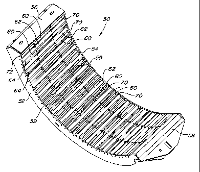
s Figure 2 is a perspective view of a concave section according to the present
invention.
Figure 3 is a side view of the concave section shown in Fig. 2.
Figure 4 is fragmentary perspective view of the concave section shown in Fig.
2 with concave wires shown partially installed.
0
Detailed Description
Fig. 1 shows an agricultural combine 10 comprising a supporting structure 12
having ground engaging means extending from the supporting structure, such as
wheels 14. A harvesting platform 16 is used for harvesting a crop and
directing it to
a feederhouse 18. The harvested crop is directed by the feederhouse 18 to a
beater
20. The beater directs the crop upwardly through the inlet transition section
22 to the
rotary crop processing unit 24. A rock trap 25 is positioned between the
feederhouse
and the beater 20.
ao The rotary crop processing unit 24 threshes and separates the harvested
crop material. It comprises a rotor or rotating member 26 radially surrounded
by a
casing 28 that together define an inlet section 30, a threshing section 32 and
a
separating section 34. The rotor 26 comprises a hollow cylindrical drum having
a
plurality of crop processing elements that engage the crop and rotate it in
the casing
25 28. The bottom of the casing has a concave 36 under the threshing section
32 and a
separating grate 38 under the separating section 34.
Grain and chaff falling through the concave 36 and the separating grate 38
are directed to cleaning system 40. The cleaning system 40 removes the chaff
and
directs the clean grain to a clean grain elevator (not shown). The clean grain
3o elevator deposits the clean grain in a grain tank 42. The clean grain in
the tank 42
can be unloaded into a grain cart or truck by an unloading auger 44.
3


CA 02297624 2000-02-03
Threshed and separated straw is discharged from the rotary crop processing
unit 24 through outlet 46 to a discharge beater (not shown). The discharge
beater in
turn propels the straw out the rear of the combine. The operation of the
combine is
controlled from operator's cab 48.
s The present invention is directed to the concave 36 located under the
threshing section 32 of the rotary crop processing unit 24. The concave of the
present invention may also be used as a separating grate. However, other types
of
separating grates may be preferred.
Three concave sections form the concave 36. A concave section 50 is shown
~o in Fig. 2. The section 50 includes a frame having two end members 52 and 54
axially spaced from one another. The end members are curved to extend
circumferentially about a portion of the rotor 26. Two straight support
members 56,
58 extend between and are joined to the curved end members. Curved
intermediate
supports 59 are arranged between the two curved end members.
Threshing is accomplished by an array of straight rectangular bars 60 and
straight round bars 62 that extend between the two curved end members 52, 54.
The bars extend parallel to the axis of the rotating member 26. The bars are
spaced
from one another to form openings 64 therebetween for grain to pass through.
The
rectangular bars provide an aggressive threshing edge while the round bars
provide
ao a rounded threshing surface that is capable of shedding crop material.
The rectangular bars 60 have inner edges 66 that define an arcuate inner
plane of the concave. The round bars 62 have a surface that is tangent to the
arcuate inner plane as shown in Fig. 3. The rectangular and round bars are
welded
to the curved end members 52, 54 and to the intermediate supports 59.
25 In a preferred embodiment, the rectangular bars and the round bars are
arranged in an alternately fashion as shown in Fig. 2. However, it will be
readily
appreciated that the rectangular bars and the round bars need not alternate
with one
another. For example, a round bar can be spaced between every two rectangular
bars or vice versa to provide a concave having different characteristics. In a
3o preferred embodiment, the rectangular bars are 6mm thick and 38mm deep. The
round bars have a diameter of 16mm. The bars are spaced approximately 28mm on
4


. CA 02297624 2000-02-03
center, resulting in the opening 64 between adjacent bars being suitable for
threshing corn and other large grains.
To reduce the opening size for smaller grains, optional wires 70 can be
inserted into the concave section, between the bars as shown in Fig. 4. The
wires 70
s are inserted through apertures 72 in the end members 52, 54 and the
intermediate
supports 59. The wires are disposed between the rectangular and round bars 60,
62. The wires extend parallel to the bars and reduce the size of the openings
64 in
the concave. The wires 70 have an enlarged, nail like, head 74 at one end that
engages the end member 54. When multiple concave sections 50 are used, the
o adjacent concave section engages the wire heads 74 to hold the wires in
place. The
concave can be utilized with all of the wires 70 in place, all of the wires 70
removed,
or a select number of wires removed to provide different opening sizes in the
concave.
In a rotary combine, a single long concave section can be utilized as the
15 concave or multiple shorter concave sections can be arranged end-to-end to
form
the concave. When multiple concave sections are provided, each section may be
configured with a different number of the wires 70 to provide different
opening sizes
in the different concave sections. An opening along the side of the combine
supporting structure 12 provides access to the concave.
ao The concave of the present invention, having both round and rectangular
bars, can be utilized in a conventional combine having a transverse threshing
cylinder as the rotating member. However, limited access to the concave may
limit
the ability to add or remove the wires 70. As such, a single size opening may
be
required in the concave when used in conventional combines. The benefits of
both
as round and rectangular bars in shedding crop material will still be
available when the
concave is used in a conventional combine.
The concave of the present invention resists plugging by virtue of the use of
round bars. The curved surface of the round bars naturally resists
accumulation of
crop material thereon. The combination of round and rectangular bars provides
more
3o aggressive threshing action then is possible with a concave comprised
solely of
round bars.


CA 02297624 2000-02-03
The invention should not be limited to the above-described embodiment, but
should be limited solely by the claims that follow.
6

Dessin représentatif
Une figure unique qui représente un dessin illustrant l'invention.
États administratifs

Pour une meilleure compréhension de l'état de la demande ou brevet qui figure sur cette page, la rubrique Mise en garde , et les descriptions de Brevet , États administratifs , Taxes périodiques et Historique des paiements devraient être consultées.

États administratifs

Titre Date
Date de délivrance prévu 2005-08-02
(22) Dépôt 2000-02-03
Requête d'examen 2000-02-03
(41) Mise à la disponibilité du public 2001-01-07
(45) Délivré 2005-08-02
Réputé périmé 2007-02-05

Historique d'abandonnement

Il n'y a pas d'historique d'abandonnement

Historique des paiements

Type de taxes Anniversaire Échéance Montant payé Date payée
Requête d'examen 400,00 $ 2000-02-03
Enregistrement de documents 100,00 $ 2000-02-03
Le dépôt d'une demande de brevet 300,00 $ 2000-02-03
Taxe de maintien en état - Demande - nouvelle loi 2 2002-02-04 100,00 $ 2002-02-01
Taxe de maintien en état - Demande - nouvelle loi 3 2003-02-03 100,00 $ 2003-01-31
Taxe de maintien en état - Demande - nouvelle loi 4 2004-02-03 100,00 $ 2004-01-21
Taxe de maintien en état - Demande - nouvelle loi 5 2005-02-03 200,00 $ 2005-01-21
Taxe finale 300,00 $ 2005-05-03
Titulaires au dossier

Les titulaires actuels et antérieures au dossier sont affichés en ordre alphabétique.

Titulaires actuels au dossier
DEERE & COMPANY
Titulaires antérieures au dossier
HEIM, DANIEL MARC
RAMP, BENJAMIN EARL
Les propriétaires antérieurs qui ne figurent pas dans la liste des « Propriétaires au dossier » apparaîtront dans d'autres documents au dossier.
Documents

Pour visionner les fichiers sélectionnés, entrer le code reCAPTCHA :


Pour visualiser une image, cliquer sur un lien dans la colonne description du document. Pour télécharger l'image (les images), cliquer l'une ou plusieurs cases à cocher dans la première colonne et ensuite cliquer sur le bouton "Télécharger sélection en format PDF (archive Zip)" ou le bouton "Télécharger sélection (en un fichier PDF fusionné)".

Liste des documents de brevet publiés et non publiés sur la BDBC .

Si vous avez des difficultés à accéder au contenu, veuillez communiquer avec le Centre de services à la clientèle au 1-866-997-1936, ou envoyer un courriel au Centre de service à la clientèle de l'OPIC.


Description du
Document 
Date
(yyyy-mm-dd) 
Nombre de pages   Taille de l'image (Ko) 
Page couverture 2000-12-29 1 57
Description 2004-09-09 6 263
Revendications 2004-09-09 2 62
Dessins représentatifs 2000-12-29 1 34
Revendications 2003-11-13 2 60
Abrégé 2000-02-03 1 15
Description 2000-02-03 6 265
Revendications 2000-02-03 2 71
Dessins 2000-02-03 3 124
Dessins représentatifs 2005-07-22 1 38
Page couverture 2005-07-22 1 63
Cession 2000-02-03 5 151
Correspondance 2003-03-13 1 2
Correspondance 2003-03-07 1 50
Poursuite-Amendment 2003-11-13 4 105
Poursuite-Amendment 2003-08-12 2 63
Poursuite-Amendment 2004-09-09 5 194
Poursuite-Amendment 2004-03-09 2 71
Correspondance 2005-05-03 1 25