Sélection de la langue

Search

Sommaire du brevet 2299689 

Énoncé de désistement de responsabilité concernant l'information provenant de tiers

Une partie des informations de ce site Web a été fournie par des sources externes. Le gouvernement du Canada n'assume aucune responsabilité concernant la précision, l'actualité ou la fiabilité des informations fournies par les sources externes. Les utilisateurs qui désirent employer cette information devraient consulter directement la source des informations. Le contenu fourni par les sources externes n'est pas assujetti aux exigences sur les langues officielles, la protection des renseignements personnels et l'accessibilité.

Disponibilité de l'Abrégé et des Revendications

L'apparition de différences dans le texte et l'image des Revendications et de l'Abrégé dépend du moment auquel le document est publié. Les textes des Revendications et de l'Abrégé sont affichés :

  • lorsque la demande peut être examinée par le public;
  • lorsque le brevet est émis (délivrance).
(12) Demande de brevet: (11) CA 2299689
(54) Titre français: DISPOSITIF DE COMMANDE ET DE SURVEILLANCE DE PORTE
(54) Titre anglais: DOOR CONTROL AND MONITORING SYSTEM
Statut: Morte
Données bibliographiques
Abrégés

Abrégé anglais


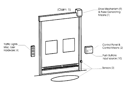
A position monitoring and control system comprises a pulse generating means
(1), in
conjunction with A control means (2) consisting of a micro control unit (MCU)
(5), and
input output unit (IOU) (6), to monitor the relative position of a door during
it's operating
cycle as well as communicate with other doors equipped with said system or a
host
computer (PC) for multi-door networking applications (Fig. 5). Said system is
then
capable of automatically compensating for various mechanical wear associated
with the
general operation of a door as well as eliminate the contact lag associated
with standard
mechanical type limit switches generally used for door control applications.
Said system
also monitors for a zero motion condition and automatically disconnects the
drive
mechanism if zero motion occurs. Said system uses an on board user interface
(7) and
display (8) to allow the user too easily modify application specific
parameters.

Revendications

Note : Les revendications sont présentées dans la langue officielle dans laquelle elles ont été soumises.


CLAIMS:

The embodiment of the invention in which an exclusive property or privilege is
claimed
are defined as follows:

1. A monitoring and control system for industrial garage door or barrier
applications
(Fig. 1), comprising an electronic pulse generating means (1) attached to a
motion
surface, such as the drive mechanism (9), to provide a relative reference of
door
travel. A control means (2) capable of receiving said electronic pulses along
with
other signals from various sensors (3) or input sources (10) associated with
door
control, the ability to process this information and perform the appropriate
output
functions for door drive mechanism control, wear compensation and
miscellaneous
user hardware control (4). A communications means (11) for inter system
communication (12) or host PC communication (13) (Fig.5). An on board user
interface means (7) and display (8) for modifying various operating
parameters.
2. A system as specified in claim 1 wherein said electronic pulse generating
means (1) is
attached to a door in such a manner as to provide a direct relation between
door
motion and the output signals generated by said pulse generating means (1).
Said
pulse-generating means (1) thus eliminates the need for mechanical type limit
switches and the contact lag associated with them.
3. A system as specified in claim 1 wherein said control means (2) comprises
two sub
systems (Fig.3). A micro control unit "MCU" (5) (Fig. 4): consisting of a
microprocessor (14), data memory (15), operating memory (16), storage memory
(17), user interface (7) and display (8), a communications interface (18), and
operation specific firmware. As well as an input output unit "IOU" (6) (Fig.2
& 3):
consisting of MCU (S) interface circuitry, input signal circuitry for
rendering various
input source signals to MCU (5) required levels or format, and output control
circuitry to render MCU (5) control signals to required output levels or
format for
door drive mechanism (9) control and miscellaneous user hardware (4) control.
4. A system as specified in claim 1 wherein said operation specific firmware
as
described in claim 3 consists of operating instructions for performing the
following:
~ Receiving output signals from said pulse-generating means as described in
claim
2. Using said signals to determine the relative position of a door at all
times.
Using said positional knowledge in association with application specific
operating
parameters to control a doors drive mechanism. Using said signals to monitor
for
a zero motion condition and automatically disconnect the drive mechanism if
one
exists. Using said positional knowledge to monitor for any variations in door
travel due to mechanical wear and automatically compensate for such wear.
~ Intersystem communication (12) and address control. Host PC communication
(13) for multi-door networking applications (Fig.5). Intersystem lockout
control
to prevent wind tunnel effects.
~ On board user interface (7) and display (8) control for modifying operating
parameters.
4


~ IOU (5) interfacing for controlling door operation requirements.
~ Monitor various time delay requirements.
~ Algorithm processing associated with various tasking requirements.


5

Description

Note : Les descriptions sont présentées dans la langue officielle dans laquelle elles ont été soumises.


CA 02299689 2000-02-18
DOOR CONTROL AND MONITORING SYSTEM
FIELD OF THE INVENTION:
This invention generally relates to the control of industrial garage doors or
barners. More particularly, the invention relates to the control and
monitoring of
high-speed industrial roll up doors.
BACKGROUND OF THE INVENTION:
It is common in devices used in the control of industrial garage doors or
barriers
that the control means consists of the following elements. 1) A limiting
device
containing standard mechanical type limit switches and a screw driven slider
setup
attached to the doors drive mechanism to determine the limit of door travel
during the
opening or closing cycles of door operation. 2) A control panel containing
electromechanical relays inter-linked to perform the required control logic
such as
time delays, sensor or push-button input control and drive mechanism control.
In
some cases a programmable logic controller "PLC" may be used to perform the
logic
requirements. In the case of electromechanical relay logic, the components are
bulky,
prone to rapid wear, and in most cases expensive. The enclosure required to
house
this type of relay logic is quite large and can cause difficulties during the
installation
process where space may be limited. This type of logic setup does not readily
lend
itself to modifications in system requirements making hardware additions and
user
modifications difficult and expensive. In the case where a PLC is used,
enclosure
requirements are reduced; however special programming knowledge, software and
equipment are required to perform any type of modifications. These
requirements
also make hardware additions and user modifications difficult and expensive.
In both
cases the limiting device used poses a multitude of problems. The standard
mechanical type limit switches associated with these limiting devices are
prone to
rapid distortion and wear requiring constant and costly re-adjustment or
replacement.
The contact lag associated with this type of mechanical limit switch can cause
a door
to not complete its required distance of travel. The decreased size of the
remaining
opening can cause a collision between the object passing through the door and
the
door itself. A collision of this type can be very costly in repairs and in
some instance
can result in personal injury.
It is common in industrial garage door or barner applications for security
features
to be incorporated that limit the possibility of damage or injury due to door
operation.
The security features commonly used in door control applications are often
prone to
rapid wear or mall function due to the environment in which they are used. The
failure rate of such components is virtually unpredictable. If a door comes
into
contact with an immovable object, referred to as a zero motion condition, and
these
security features have failed, the drive mechanism for the door will continue
to
operate. This type of event can cause extensive and costly damage to both the
object
wedged in the door and to the door itself and in some cases can result in
severe
personal injury.


CA 02299689 2000-02-18
It is common in industrial garage door or barrier applications for the drive
mechanism to incorporate frictional devices for torque transfer and breaking.
The
constant mechanical wear associated with these drive components creates the
necessity for chronic and costly re-adjustment and preventive maintenance
schedules.
It is common in industrial garage door or barner applications for multiple
doors to
be installed in the same building. Having two opposing doors open
simultaneously in
a building can create a wind tunnel effect inside said building that can
rapidly
increase heating or air conditioning costs as well as cause discomfort to
personnel.
SUMMARY OF THE INVENTION:
Said invention overcomes the limitations and problems associated with
industrial
garage door or barrier applications buy using an electronic pulse generating
means
attached to a motion surface of the door instead of the standard mechanical
limiting
devices commonly used, in conjunction with a purpose built microprocessor
based
control means capable of signal processing and analyses. Said system has been
developed using a pulse generating means to precisely monitor a doors position
thus
eliminating the various problems caused by mechanical type limit switches. The
ability to precisely monitor a door's position allows computation and
automatic
compensation of any variations in door travel characteristics due to the
mechanical
wear of drive components, thus decreasing the maintenance requirements of such
components. Using such a pulse generating means allows a zero motion condition
to
be reliably detected by simply monitoring the positional changes of door
travel while
the drive mechanism is active and disconnecting the drive control if zero
motion
occurs. The advantage of this type of safety feature is that if it fails the
door itself
becomes inoperable. Using a purpose built microprocessor based control means
renders inter door communication possible. This ability to communicate between
doors is used to prevent two opposing doors from being open at the same time
thus
minimizing the potential for wind tunnel effects. A simple user interface and
display
are also incorporated into the control means to allow for easy user
modifications to
the system via easy to access menu selections. The control means, being
purpose
built for industrial garage door or barrier applications means that all known
user
requirements have been incorporated in such a device thus minimizing the time
and
cost of performing hardware additions and user modifications.

Dessin représentatif
Une figure unique qui représente un dessin illustrant l'invention.
États administratifs

Pour une meilleure compréhension de l'état de la demande ou brevet qui figure sur cette page, la rubrique Mise en garde , et les descriptions de Brevet , États administratifs , Taxes périodiques et Historique des paiements devraient être consultées.

États administratifs

Titre Date
Date de délivrance prévu Non disponible
(22) Dépôt 2000-02-18
(41) Mise à la disponibilité du public 2001-08-18
Demande morte 2005-02-18

Historique d'abandonnement

Date d'abandonnement Raison Reinstatement Date
2004-02-18 Taxe périodique sur la demande impayée

Historique des paiements

Type de taxes Anniversaire Échéance Montant payé Date payée
Le dépôt d'une demande de brevet 150,00 $ 2000-02-18
Taxe de maintien en état - Demande - nouvelle loi 2 2002-02-18 50,00 $ 2002-02-06
Taxe de maintien en état - Demande - nouvelle loi 3 2003-02-18 50,00 $ 2003-02-18
Titulaires au dossier

Les titulaires actuels et antérieures au dossier sont affichés en ordre alphabétique.

Titulaires actuels au dossier
SKOWRONSKI, MICHAEL J.
Titulaires antérieures au dossier
S.O.
Les propriétaires antérieurs qui ne figurent pas dans la liste des « Propriétaires au dossier » apparaîtront dans d'autres documents au dossier.
Documents

Pour visionner les fichiers sélectionnés, entrer le code reCAPTCHA :


Pour visualiser une image, cliquer sur un lien dans la colonne description du document. Pour télécharger l'image (les images), cliquer l'une ou plusieurs cases à cocher dans la première colonne et ensuite cliquer sur le bouton "Télécharger sélection en format PDF (archive Zip)" ou le bouton "Télécharger sélection (en un fichier PDF fusionné)".

Liste des documents de brevet publiés et non publiés sur la BDBC .

Si vous avez des difficultés à accéder au contenu, veuillez communiquer avec le Centre de services à la clientèle au 1-866-997-1936, ou envoyer un courriel au Centre de service à la clientèle de l'OPIC.


Description du
Document 
Date
(yyyy-mm-dd) 
Nombre de pages   Taille de l'image (Ko) 
Page couverture 2001-08-16 1 41
Revendications 2000-02-18 2 76
Abrégé 2000-02-18 1 24
Description 2000-02-18 2 131
Dessins 2000-02-18 3 51
Dessins représentatifs 2001-08-16 1 10
Correspondance 2000-03-23 1 1
Cession 2000-02-18 2 104
Taxes 2003-02-18 1 156
Taxes 2002-02-06 1 66