Sélection de la langue

Search

Sommaire du brevet 2299861 

Énoncé de désistement de responsabilité concernant l'information provenant de tiers

Une partie des informations de ce site Web a été fournie par des sources externes. Le gouvernement du Canada n'assume aucune responsabilité concernant la précision, l'actualité ou la fiabilité des informations fournies par les sources externes. Les utilisateurs qui désirent employer cette information devraient consulter directement la source des informations. Le contenu fourni par les sources externes n'est pas assujetti aux exigences sur les langues officielles, la protection des renseignements personnels et l'accessibilité.

Disponibilité de l'Abrégé et des Revendications

L'apparition de différences dans le texte et l'image des Revendications et de l'Abrégé dépend du moment auquel le document est publié. Les textes des Revendications et de l'Abrégé sont affichés :

  • lorsque la demande peut être examinée par le public;
  • lorsque le brevet est émis (délivrance).
(12) Brevet: (11) CA 2299861
(54) Titre français: FILTRAGE DE COURANT DE DEFAUT POUR DISJONCTEUR DIFFERENTIEL
(54) Titre anglais: GFCI GROUND FAULT CURRENT FILTERING
Statut: Périmé
Données bibliographiques
(51) Classification internationale des brevets (CIB):
  • H01H 83/02 (2006.01)
  • H02H 1/04 (2006.01)
  • H02H 3/33 (2006.01)
(72) Inventeurs :
  • ZARETSKY, AL (Etats-Unis d'Amérique)
(73) Titulaires :
  • LEVITON MANUFACTURING CO., INC. (Etats-Unis d'Amérique)
(71) Demandeurs :
  • LEVITON MANUFACTURING CO., INC. (Etats-Unis d'Amérique)
(74) Agent: RIDOUT & MAYBEE LLP
(74) Co-agent:
(45) Délivré: 2008-08-05
(22) Date de dépôt: 2000-02-29
(41) Mise à la disponibilité du public: 2000-09-01
Requête d'examen: 2005-02-02
Licence disponible: S.O.
(25) Langue des documents déposés: Anglais

Traité de coopération en matière de brevets (PCT): Non

(30) Données de priorité de la demande:
Numéro de la demande Pays / territoire Date
09/260,991 Etats-Unis d'Amérique 1999-03-01

Abrégés

Abrégé français

Un système permettant de contrôler la réponse d'un disjoncteur différentiel, en présence de courants de fuite aléatoires en raison de la présence d'un milieu conducteur tel que de l'eau ou de la glace. Le signal à partir d'un transformateur différentiel à noyau magnétique est appliqué à deux filtres en parallèle. Le premier filtre passe la fréquence fondamentale de la source et le second filtre passe une large bande de fréquences commençant à deux fois la fréquence fondamentale. Les sorties des filtres sont appliquées à un microprocesseur qui manipule les sorties de filtre et compare certaines des sorties de filtre à un motif de courant de fuite stocké attendu. Le microprocesseur fait fonctionner un relais pour déconnecter la charge de la source lorsqu'une condition de défaut existe.


Abrégé anglais

A system for controlling the response of a ground fault circuit interrupter in the presence of random leakage currents due to the presence of a conductive media such as water or ice. The signal from a magnetic core differential transformer is applied to two filters in parallel. The first filter passes the fundamental frequency of the source and the second filter passes a broad band of frequencies starting at twice the fundamental frequency. The output of the filters are applied to a microprocessor which manipulates the filter outputs and compares certain of the filter outputs to a stored pattern of expected current leakage. The microprocessor operates a relay to disconnect the load from the source when a fault condition exists.

Revendications

Note : Les revendications sont présentées dans la langue officielle dans laquelle elles ont été soumises.


I claim:


1. A GFCI fault current filtering system, comprising:

a) differential transformer having an aperture therethrough;

b) a phase line passing through said transformer aperture and forming a first
one turn
winding on said transformer, said phase line having a first phase line end and
a second
phase line end and coupled, at said first phase line end, to a phase conductor
of an AC
power source and, at said second phase line end, to a phase terminal of an
electrical
load;

c) a neutral line passing through said transformer aperture and forming a
second one
turn winding on said transformer, said neutral line having a first neutral
line end and a
second neutral line end and coupled, at said first neutral line end to a
neutral
conductor of said AC power source and, at said second neutral line end, to a
neutral
terminal of said electrical load;

d) a secondary winding on said differential transformer to provide a first
signal when
the current through said neutral line does not equal the current through said
phase
line;

e) a first filter coupled to said secondary winding and tuned to pass a
selected
frequency signal of said first signal;

f) a second filter coupled to said secondary winding and tuned to pass a band
of
selected frequencies signal of said first signal;

g) a microprocessor coupled to said first filter to received said selected
frequency
signal and compute a first moving average of said selected frequency signal
and said
microprocessor is coupled to said second filter to receive said band of
selected
frequencies signal and compute a second moving average of said band of
selected
frequencies signal; and


6


h) selectively operable switch device in said phase and neutral lines and
responsive to
an output of said microprocessor to operate said selectively operable switch
device to
open said phase and neutral lines and interrupt the flow of current to an
electrical load
coupled to said load phase and neutral terminals.

2. A GFCI ground fault current filtering system, as defined in Claim 1,
further comprising:
a) an amplifier having input terminals to receive said first signal from said
secondary
winding on said differential transformer and a first output coupled to said
first filter
and said second filter.

3. A GFCI ground fault current filtering system, as defined in Claim 1,
further comprising:
a) a first analog to digital converter with an input terminal coupled to said
first filter
and an output terminal coupled to said microprocessor to provide a digitized
selected
frequency signal to said microprocessor; and

b) a second analog to digital converter with an input terminal coupled to said
second
filter and an output terminal coupled to said microprocessor to provide a
digital band
of selected frequencies signal to said microprocessor.

4. A GFCI ground fault current filtering system, as defined in Claim 2 further
comprising:
a) a first analog to digital converter with an input terminal coupled to said
first filter
and an output terminal coupled to said microprocessor to provide a digitized
selected
frequency signal to said microprocessor; and

b) a second analog to digital converter with an input terminal coupled to said
second
filter and an output terminal coupled to said microprocessor to provide a
digitized
band of selected frequencies signal to said microprocessor.

5. A GFCI ground fault current filtering system, as defined in Claim 1,
further comprising:
a) a GFCI coupled to a first output terminal of said microprocessor and to
said
selectively operable switch device to operate said switch device to an open
position
when said first moving average exceeds a first predetermined value.


7


6. A GFCI ground for fault current filtering system, as defined in Claim 2,
further
comprising:

a) a GFCI coupled to a first output terminal of said microprocessor and to
said
selectively operable switch device to operate said switch device to an open
position
when said first moving average exceeds a first predetermined value.

7. A GFCI ground fault current filtering system, as defined in Claim 1,
wherein said
selectively operable switch device receives an output of said microprocessor
to operate said
switch device when said second moving average signal exceeds a second
predetermined
value.

8. A GFCI ground fault current filtering system, as defined in Claim 2,
wherein said
selectively operable switch device receives an output of said microprocessor
to open said
switch device when said second moving average signal exceeds a second
predetermined
value.

9. A GFCI ground fault current filtering system, as defined in Claim 1,
wherein said
selectively operable switch device receives an output of said microprocessor
to open said
switch device when said band of selected frequencies signal does not match a
signal stored in
the memory of said microprocessor.

10. A GFCI ground fault current filtering system, as defined in Claim 2,
wherein said
selectively operable switch device receives an output of said microprocessor
to open said
switch device when said band of selected frequencies signal does not match a
signal stored in
the memory of said microprocessor.

11. A method of operating a selectively operable switch device to open a phase
line and a
neutral line between a source of AC power and an electrical load, comprising
the steps of:
a) extending said phase line through an aperture of a magnetic core
differential
transformer;

b) extending said neutral line through the aperture of said magnetic core
differential
transformer;


8


c) applying an output signal of said differential transformer to a first
filter to select a
first signal and to a second filter to select a second signal;

d) applying said first and said second signals to a microprocessor;

e) manipulating said first signal and said second signal in accordance with
criteria
stored in said microprocessor and providing a third signal; and

f) providing an operating signal to said selectively operable switch device to
cause
switch device to open said phase and neutral lines in response to said third
signal
applied by said microprocessor to said operable switch device.

12. A method, as set forth in Claim 11, further comprising the step of:

a) selecting said magnetic core differential transformer to have a broadband
response
in excess of any expected current leakage frequencies.

13. A method, as set forth in Claim 12, further comprising the step of
a) amplifying the output signal of said differential transformer.
14. A method, as set forth in Claim 11, wherein:

a) said first filter passes a single frequency signal; and
b) said second filter passes a band of frequencies

15. A method, as set forth in Claim 12, wherein:

a) said first filter passes a single frequency signal; and
b) said second filter passes a band of frequencies.

9

Description

Note : Les descriptions sont présentées dans la langue officielle dans laquelle elles ont été soumises.


CA 02299861 2000-02-29

Docket No.: 0267-001-1270
GFCI GROUND FAULT CURRENT FILTERING

Albert Zaretsky

BACKGROUND OF THE INVENTION
Field of the Invention

The invention is directed to the field of ground fault circuit interrupters
(GFCIs)
and more particularly GFCIs to protect electrical devices where there are
normally erratic current
leakages to ground.

Description of the Prior Art

There are some situations where the normal ground current leakage approaches
or
in some cases is greater than that required to trigger a GFCI. Two such
examples are
refrigerators and washing machines, where the leakages due to a water
environment or melting
ice cause erratic random ground leakages. In cases such as these, a
conventional GFCI can not
be used, thus compromising the safety of the user. No device is known which
satisfactorily
provides GFCI protection under these conditions.

SUMMARY OF THE INVENTION

The instant invention describes a new device which will facilitate accurate
and
correct triggering due to ground leakage in the presence of erratic and random
ground leakage. A
differential transformer detects imbalances in the current through the phase
and neutral lines
connecting a source to an electrical load. The output of the transformer is
amplified and fed to
two filters. A first filter is sharply tuned to pass only the fundamental
frequency signal. The


CA 02299861 2000-02-29

second filter is a band pass filter that has a lower cutoff in excess of twice
the fundamental
frequency to block the second harmonic and twice the fundamental frequency.
The outputs of
the filters are fed to analog to digital converters and are inputted to inputs
of a microprocessor.
The program of the microprocessor senses each of the two filter outputs
separately and computes
a moving average of each. The moving average time period is determined by the
leaking
characteristics of the appliance to be protected. When either average exceeds
by a preset amount
for a predetermined period of time, this signifies a ground leakage above the
normal ground
leakage, causing a trip signal to be generated which opens contacts in the
phase and neutral lines
thus separating the AC power source from the electrical load. It is an object
of the instant
invention to provide a GFCI which will provide proper triggering of the
operating relay in the
presence of erratic and random ground leakage.

It is another object of the instant invention to employ a microprocessor to
compare ground leakage to a stored pattern of permitted ground leakage for a
particular device.
It is yet another object of the instant invention to provide a device which
can

respond to abnormal ground leakage current while retaining the normal
functions of a GFCI.
Other objects and features of the invention will be pointed out in the
following
description and claims and illustrated in the accompanying drawings, which
disclose, by way of
example, the principles of the invention, and the best mode which is presently
contemplated for
carrying them out.

BRIEF DESCRIPTION OF THE DRAWING

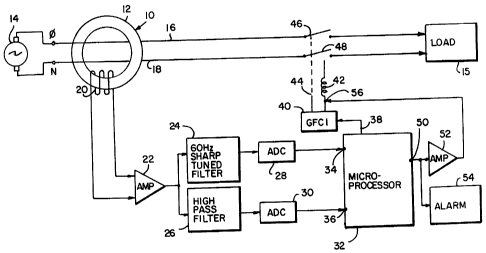
The sole figure is a schematic diagram of the instant invention.
2


CA 02299861 2000-02-29

DESCRIPTION OF THE PREFERRED EMBODIMENT

A broadband differential transformer 10 in the shape of a toroid 12 receives
therethrough a phase line 16 and a neutral line 18 from a source of AC power
14. The phase line
16 and the neutral line 18 each act as a single turn winding for the
transformer 10. The
differential transformer 10 frequency response band must be greater than the
expected random
ground leakage frequencies. A seconding winding 20 couples the differential
signal to an
amplifier 22. Amplifier 22 is coupled to the input of a 60 Hz sharp-tuned
filter 24 which only
passes the fundamental 60 Hz frequency. The amplifier 22 is also coupled to
the input of a high
pass filter 26 which has a band starting at a frequency above 120 Hz, twice
the fundamental
frequency so as to block the second harmonic and the fundamental which might
be generated by
switching loads each half cycle.

The output of filter 24 is applied to a first analog to digital converter 28
while the
output of filter 26 is applied to a second analog to digital converter 30. The
outputs of filters 24
and 26 are thus converted to a digital format and applied to input terminals
34 and 36,

respectively of a microprocessor 32. The microprocessor 32 computes a moving
average for
each input at terminals 34 and 36. The moving average time period is
determined by the leakage
characteristics of the device to be protected. When either moving average
exceeds a preset
amount for a predetermined time period, this signifies a ground leakage above
the normal ground
leakage causing a trigger signal to be generated which opens the lines 16 and
18 as will be
described below.

The microprocessor 32 also stores a pattern of the leakage characteristics of
the
devices to be protected and provides a trip signal in the event an abnormal
ground leakage as
3


CA 02299861 2000-02-29

indicated by no match between the stored pattern and the pattern of the
applied waves such as
may occur due to arcing or there is a high moving average signal.

Thus, if the moving average produced by the microprocessor 32 in response to
the
power line frequency signal applied at terminal 34, the normal GFCI ground
fault, exceeds by a
given amount and for a given period of time, a signal is applied to a GFCI 40
via output terminal
38. The GFCI, as is well known, has a control device such as a silicon
controlled rectifier which
responds to a fault current to operate the solenoid 42 (See U.S. Patent No.
4,709,293 issued

November 24, 1987 and assigned to the assignee of the instant invention). The
solenoid plunger
44 is attached to movable contact arms 46 and 48 to open the phase line 16 and
the neutral line
18. When the signal is removed from the GFCI 40, the solenoid 42 is
deactivated and the
plunger 44 returns to a rest position (not shown) where the movable contact
arms 46 and 48
move to their closed positions in contact with fixed contacts to close the
phase line 16 and
neutral line 18 between the AC power source 14 and an electrical load 15.

a The signal applied to terminal 36, the erratic random ground leakage of a
water
operated appliance, of microprocessor 32 is evaluated to determine whether its
moving average is
above a limit stored in the memory of microprocessor 32. In the event the
signal exceeds the
limit for the moving average, an output signal is applied to an amplifier 52
from output terminal
50 of microprocessor 32. The output at terminal 50 can also be applied to an
alarm 54 which can
be a visual alarm such as a light, an auditory alarm such as a bell or buzzer
or a combination of
both. The signal at output terminal 50 could also be transmitted to a remote
location (not
shown). The output of amplifier 52 is applied to terminal 56 of solenoid 42 to
cause the plunger
44 to open the movable contact arms 46, 48 and open the phase and neutral
lines 16, 18

4


CA 02299861 2000-02-29
respectively.

The microprocessor 32 also compares the signal at terminal 36 with a stored
current pattern in the memory of the microprocessor 32. The pattern stored is
a typical current
wave for the device being protected and includes the normal current and any
expected current
leakage which is typical of the device in operation. The incoming signal on
input terminal 36 is
cross-correlated with the stored program wave to determine leakage randomness.
An arc can
also be detected by the signal applied to the input terminal 36. The output
terminal 50 provides a
signal to amplifier 52 when the detected current pattern exceeds the stored
current pattern by
more than a given amount such as when arcing occurs. The output of amplifier
52 is applied to
terminal 56 of the solenoid 42 as above described. More complex mathematical
methods of
waveform analysis could also be used, for example, least squares analysis, in
place of the moving
averages.

While there have been shown and described and pointed out the fundamental
novel features of the invention as applied to the preferred embodiment, as is
presently
contemplated for carrying them out, it will be understood that various
omissions and
substitutions and changes of the form and details of the device illustrated
and in its operation
may be made by those skilled in the art, without departing from the spirit of
the invention.


Dessin représentatif
Une figure unique qui représente un dessin illustrant l'invention.
États administratifs

Pour une meilleure compréhension de l'état de la demande ou brevet qui figure sur cette page, la rubrique Mise en garde , et les descriptions de Brevet , États administratifs , Taxes périodiques et Historique des paiements devraient être consultées.

États administratifs

Titre Date
Date de délivrance prévu 2008-08-05
(22) Dépôt 2000-02-29
(41) Mise à la disponibilité du public 2000-09-01
Requête d'examen 2005-02-02
(45) Délivré 2008-08-05
Expiré 2020-03-02

Historique d'abandonnement

Il n'y a pas d'historique d'abandonnement

Historique des paiements

Type de taxes Anniversaire Échéance Montant payé Date payée
Enregistrement de documents 100,00 $ 2000-02-29
Le dépôt d'une demande de brevet 300,00 $ 2000-02-29
Taxe de maintien en état - Demande - nouvelle loi 2 2002-02-28 100,00 $ 2002-01-23
Taxe de maintien en état - Demande - nouvelle loi 3 2003-02-28 100,00 $ 2002-12-13
Taxe de maintien en état - Demande - nouvelle loi 4 2004-03-01 100,00 $ 2004-01-28
Taxe de maintien en état - Demande - nouvelle loi 5 2005-02-28 200,00 $ 2005-02-01
Requête d'examen 800,00 $ 2005-02-02
Taxe de maintien en état - Demande - nouvelle loi 6 2006-02-28 200,00 $ 2006-01-05
Taxe de maintien en état - Demande - nouvelle loi 7 2007-02-28 200,00 $ 2007-01-22
Taxe de maintien en état - Demande - nouvelle loi 8 2008-02-29 200,00 $ 2007-12-18
Taxe finale 300,00 $ 2008-05-13
Taxe de maintien en état - brevet - nouvelle loi 9 2009-03-02 200,00 $ 2009-01-09
Taxe de maintien en état - brevet - nouvelle loi 10 2010-03-01 250,00 $ 2010-01-07
Taxe de maintien en état - brevet - nouvelle loi 11 2011-02-28 250,00 $ 2011-01-25
Taxe de maintien en état - brevet - nouvelle loi 12 2012-02-29 250,00 $ 2012-01-19
Taxe de maintien en état - brevet - nouvelle loi 13 2013-02-28 250,00 $ 2013-01-18
Taxe de maintien en état - brevet - nouvelle loi 14 2014-02-28 250,00 $ 2014-01-22
Taxe de maintien en état - brevet - nouvelle loi 15 2015-03-02 450,00 $ 2015-01-19
Taxe de maintien en état - brevet - nouvelle loi 16 2016-02-29 450,00 $ 2016-01-12
Taxe de maintien en état - brevet - nouvelle loi 17 2017-02-28 450,00 $ 2017-01-13
Taxe de maintien en état - brevet - nouvelle loi 18 2018-02-28 450,00 $ 2018-01-12
Taxe de maintien en état - brevet - nouvelle loi 19 2019-02-28 450,00 $ 2019-01-15
Titulaires au dossier

Les titulaires actuels et antérieures au dossier sont affichés en ordre alphabétique.

Titulaires actuels au dossier
LEVITON MANUFACTURING CO., INC.
Titulaires antérieures au dossier
ZARETSKY, AL
Les propriétaires antérieurs qui ne figurent pas dans la liste des « Propriétaires au dossier » apparaîtront dans d'autres documents au dossier.
Documents

Pour visionner les fichiers sélectionnés, entrer le code reCAPTCHA :


Pour visualiser une image, cliquer sur un lien dans la colonne description du document. Pour télécharger l'image (les images), cliquer l'une ou plusieurs cases à cocher dans la première colonne et ensuite cliquer sur le bouton "Télécharger sélection en format PDF (archive Zip)" ou le bouton "Télécharger sélection (en un fichier PDF fusionné)".

Liste des documents de brevet publiés et non publiés sur la BDBC .

Si vous avez des difficultés à accéder au contenu, veuillez communiquer avec le Centre de services à la clientèle au 1-866-997-1936, ou envoyer un courriel au Centre de service à la clientèle de l'OPIC.


Description du
Document 
Date
(yyyy-mm-dd) 
Nombre de pages   Taille de l'image (Ko) 
Dessins représentatifs 2000-08-28 1 9
Abrégé 2007-12-06 1 21
Abrégé 2000-02-29 1 21
Description 2000-02-29 5 206
Revendications 2000-02-29 5 165
Dessins 2000-02-29 1 18
Page couverture 2000-08-28 1 36
Revendications 2007-06-12 4 143
Dessins représentatifs 2008-07-21 1 10
Page couverture 2008-07-21 1 41
Taxes 2002-01-23 1 33
Cession 2000-02-29 4 220
Taxes 2002-12-13 1 31
Taxes 2004-01-28 1 33
Taxes 2005-02-01 1 27
Correspondance 2004-02-23 1 18
Taxes 2004-01-28 1 36
Poursuite-Amendment 2005-02-02 1 23
Taxes 2006-01-05 1 27
Poursuite-Amendment 2006-12-13 2 59
Taxes 2007-01-22 1 29
Poursuite-Amendment 2007-06-12 8 289
Taxes 2007-12-18 1 29
Correspondance 2008-05-13 1 33
Cession 2009-07-15 15 586