Note : Les descriptions sont présentées dans la langue officielle dans laquelle elles ont été soumises.
CA 02302112 2000-03-27
CANADIAN PATENT
File No. 45200.2
THREAD PROTECTOR REMOVER
FIELD OF THE INVENTION
The present invention relates to a device for removing thread protectors
installed
on lengths of pipe, tubing or the like.
BACKGROUND OF THE INVENTION
In the oil well drilling and servicing industry, lengths of pipe or tubing are
used
which have a box end and a pin end which are both threaded. The pin end
engages the box end
of an adjacent length of pipe to create a pipe or tubing string. The threads
at both ends of the
pipe may be damaged while being transported, unloaded or stored rendering the
pipe unuseable.
To guard against such damage, it is common to install thread protectors which
engage the
threaded ends of the pipe.
There is no industry standard for thread protectors and they may be offered in
various configurations. The thread protectors are most often made from plastic
although they
may also be made from metal. Each model of thread protector must include two
configurations,
one to fit on the box end and another to fit on the pin end of the pipe.
Therefore, one thread
protector will have an external thread to fit on the box end while another
will have an internal
thread to fit on the pin end.
It is often very difficult to conveniently remove thread protectors and very
often
brute force is required to remove them, often resulting in the very type of
damage that the thread
protectors are meant to protect against. As well, the wide variety of the
different thread
protectors has hindered the development of a universal type thread protector
remover which
would be effective with all of the different thread protectors currently
available and developed in
the future.
CA 02302112 2000-03-27
Therefore, there is a need in the art for thread protector removers which are
convenient and safe to use and which are effective with most makes and
configurations of thread
protectors commonly available.
SUMMARY OF THE INVENTION
The invention is a tool for removing or tightening thread protectors installed
on
lengths of pipe having threaded ends. In one aspect of the invention, the tool
comprises:
(a) a disc-shaped housing defining an internal chamber and having a perimeter
defining at least two openings;
(b) a drive member rotatably mounted within the internal chamber including
means
by which rotational force may be applied to the drive member; and
(c) at least two thread protector gripping members each of which engages the
drive
member and each of which is movable between an extended position wherein a
portion of the member extends through a perimeter opening, and a retracted
position within the housing;
(d) wherein rotational movement of the drive member causes the thread
protector
gripping members to move to their extended position and engage the thread
protector.
In one embodiment, the tool includes biasing means for biasing the thread
protector gripping
members towards their retracted position. Preferably, the force with which the
thread protector
gripping members are moved towards their extended position increases as the
rotational force
applied to the drive member increases.
In one embodiment, each gripping member rotationally engages the housing and
comprises a gear section having a curved edge defining a plurality of gear
teeth, and a wing
section having an outboard tip; and the drive member is a circular disk having
an edge defining a
2
CA 02302112 2000-03-27
plurality of gear teeth complementary to and engaging the gear teeth on the
center section of the
gripping member, such that rotation of the drive member causes rotation of the
gripping member
such that the outboard tip of each gripping member extends through a perimeter
opening.
Preferably, each gripping member has two wing sections arrayed substantially
symmetrically on
either side of the center section, each wing section having an outboard tip.
Each outboard tip may
be a sharp tip which may penetrate the surface of the thread protector. The
gripping member
may be a semi-circular disk.
In another embodiment, each gripping member is an elongate sliding pin
oriented radially
within the housing, slidingly engaging the housing and having an outer end and
an inner end; the
outer end of each sliding pin may engage the thread protector and the inner
end of each sliding
pin defines a drive member engaging surface; and wherein the drive member is
an eccentrically
shaped disk having a peripheral surface which engages the inner ends of the
sliding pins such
that rotation of the drive member causes outward radial movement of the
sliding pins, thereby
causing the outer ends of each sliding pin to extend through a perimeter
opening. 'The outer end
of each sliding pin may be a sharp tip which may penetrate the surface of the
thread protector.
In another aspect of the invention, the invention comprises a tool for
removing or
tightening pipe thread protectors having a cylindrical opening, said tool
comprising:
(a) a disc-shaped housing which may be inserted into the cylindrical opening,
said
housing defining an internal chamber and having a circular perimeter defining
three openings spaced around the perimeter;
(b) a drive gear rotatably and centrally mounted within the internal chamber
having a
plurality of gear teeth around the circumference of the drive gear;
(c) three gripping wings, each comprising a semi-circular disk having a
central
section having a curved edge defining a plurality of gear teeth complementary
to
and engaging the gear teeth of the drive gear and two outboard sections having
an
outboard tip on either side of the central section, wherein the gripping wing
is
rotatably mounted to the housing and moveable between an extended position
3
CA 02302112 2000-03-27
where one outboard tip is extended through a perimeter opening and a retracted
position where both outboard tips are contained within the housing;
wherein rotation of the drive gear causes rotation of the gripping wings to
their extended
position.
In another aspect of the invention, the invention comprises a combination tool
for
removing or tightening thread protectors having splines or grooves, said tool
comprising:
(a) a circular ring having inner grooves which are complementary to the
splines of a
thread protector;
(b) a disk having outer lugs which are complementary to the grooves of a
thread
protector;
(c) wherein said ring and said disk are attached back to back and face in
opposite
directions; and
(d) means for applying rotational force to the tool, said means provided on
both sides
of the tool.
The mean for applying rotational force may be a drive stem having a square or
hexagonal
configuration which permits the use of conventional wrenchs or drive sockets.
BRIEF DESCRIPTION OF THE DRAWINGS
The invention will now be described by way of an exemplary embodiment with
reference to the accompanying simplified, diagrammatic, not-to-scale drawings.
In the drawings:
FIGURE 1 illustrates the preferred embodiment of the invention, positioned for
use in removing a thread protector from the pin end of the pipe.
4
CA 02302112 2000-03-27
FIGURE 2 illustrates the preferred embodiment positioned for use in removing a
thread protector from the box end of a pipe.
FIGURE 3 is a cross-section through the cam-actuated embodiment of the
invention, with its thread protector gripping members in the retracted
position.
FIGURE 4 is a cross-section through the cam-actuated embodiment of the
invention, with its thread protector gripping members in the extended
position.
FIGURE 5 is a cross-section through the gear-actuated embodiment of the
invention, with its thread protector gripping members in the retracted
position.
FIGURE 5A is a cross-section of a variant of a gear-activated embodiment, with
the thread protector gripping member in the extended position.
FIGURE 6 illustrates an alternative embodiment of the invention, positioned
for
removing a splined or notched thread protector from the pin end f a pipe.
FIGURE 7 is a cross-section through the splined or notched thread protector
shown in Figure 6.
FIGURE 8 and 9 are views of the alternative embodiment of the invention
depicted in Figure 6.
DETAILED DESCRIPTION OF THE INVENTION
The present invention is a tool, generally represented by reference numeral
(10) in
Figures l and 2, for removing a thread protector from either the pin end or
the box end of a
length of pipe. Refernng to Figure 1, the pin end of a pipe (40) has external
tapered threads (42).
A pin-end thread protector (50) having internal tapered threads (52) has been
twisted onto the pin
end of pipe (40) such that internal threads (52) of thread protector (50)
engage and protectively
cover the external threads (42) of pipe (40). Thread protector (50) has
interior cylindrical surface
5
CA 02302112 2000-03-27
(54) defining cylindrical bore (55) having a diameter the same as or slightly
smaller than that of
the bore pipe (40). Thread protector (50) also has exterior perimeter surface
(56) which may be
of any convenient geometric configuration. Thread protector (50) will commonly
be made of a
synthetic material such as plastic.
The tool (10) has a housing (20) having cylindrical perimeter surface (21),
the
diameter of which is slightly smaller than the cylindrical bore (55) of the
thread protector (50),
such that housing (20) may be inserted into cylindrical bore (55) as
schematically indicated by
arrows "A". Housing (20) has a plurality of thread protector gripper openings
(22) which open
out through the perimeter surface (21 ); the purpose of gripper openings (22)
is explained in
1 S greater detail hereinafter.
Positioned across the upper end of housing (20) and connected thereto is a
retainer member (30), which serves the function of holding housing (20) in
position within
cylindrical bore (55) of thread protector (50) such that gripper openings (22)
lie within the depth
of cylindrical bore (55) when housing (20) has been inserted thereinto.
Retainer member (30)
may be simply a flat bar, but in a preferred embodiment it will be a circular
flat plate large
enough to cover substantially the entire top surface of thread protector (50),
as indicated in
Figures l and 2. A drive stem (32), rotatably and co-axially mounted to
housing (20), has a
hollow socket (34) to facilitate operation of tool (10) using a conventional
socket wrench or
similar device. Hollow socket (34) may be of square, hexagonal, or other
appropriate
configuration to permit use of a desired style of wrench. Alternatively, drive
stem (32) may have
a square, hexagonal, or other appropriate external configuration so as to
permit engagement
thereof with a crescent wrench or open-end wrench. In a preferred embodiment,
retainer
member (30) will have a handle (36) which may be gripped by an operator to
position the tool
(10) within the thread protector (50).
Figure 2 also depicts tool (10) as described above, but positioned for use in
removing a thread protector from the box end of pipe (40) having internal
tapered threads (44).
A box-end thread protector (60) having external tapered threads (64) has been
twisted into the
box end of pipe (40) such that external threads (64) of thread protector (60)
engage and
protectively cover the internal threads (44) of pipe (40). Thread protector
(60) has interior
6
CA 02302112 2000-03-27
cylindrical surface (62) defining cylindrical bore (65). The top, or upper,
end of thread protector
(60) may also have perimeter flange (66) which further protects the end of
pipe (40).
Figures 3 and 4 are cross-sectional views illustrating the inner mechanism of
a
cam-actuated embodiment of tool ( 10). Housing (20) defines central chamber
(26), and gripper
openings (22) which, in the embodiment shown in Figures 3 and 4, are elongate
slots emanating
radially outward from central chamber (26) and opening through the perimeter
surface (21 ) of
the housing (20). The drive member is a cam rotor (28), which is an irregular
disk defining a
plurality of curved cam lobes (28b) and a corresponding number of curved cam
valleys (28c).
The cam rotor (28) is fixedly mounted to cam pivot pin (28a), which in turn is
co-axial with and
rigidly connected to drive stem (32) and is rotatably mounted within housing
(20). The number
of cam lobes (28b) and cam valleys (28c) matches the number of gripper
openings (22).
Positioned in each gripper opening (22) is a thread protector gripper (24),
which in the
embodiment shown in Figures 3 and 4 is an elongate gripper pin having a
pointed outer end (24)
and a round inner end (24b). Each gripper pin (24) is slidably mounted within
its corresponding
gripper opening (22). In the preferred embodiment, each gripper opening (22)
is provided with
biasing means, such as a spring (not shown), which automatically positions the
gripper pin (24)
in the "retracted" position illustrated in Figure 3 when the tool (10) is not
being operated.
Figure 4 specifically illustrates the operation of a cam-actuated embodiment
of
the invention described above in relation to Figure 3. In Figure 4, cam rotor
(28) has been
rotated in the direction indicated by arrow "R". The rotation of cam rotor
(28) has caused cam
lobes (28b) to engage the curved ends (24b) of gripper pins (24), with the
result that gripper pins
(24) are urged radially outward within gripper openings (22), and pointed ends
(24a) of gripper
pins (24) project beyond perimeter surface (21 )of housing (20).
Therefore it may be readily seen, having reference to Figures l and 2, that
when
housing (20) of the cam-actuated embodiment of the present invention has been
inserted into the
bore (55 or 65) of a thread protector (SO or 60) on a pipe (40), and drive
stem (32) is rotated in a
selected direction, the pointed ends (24a) of gripper pins (24) will project
out of gripper openings
(22) and press into the comparatively soft material of the inner surface (54
or 62) of the thread
protector (50 or 60). With the gripper pins (24) thus engaging the thread
protector (50 or 60),
7
CA 02302112 2000-03-27
and with movement of pipe (40) being restrained, further rotation of drive
stem (32) will urge the
thread protector (50 or 60) to rotate relative to the pipe (40), thereby
loosening or tightening the
thread protector (SOor 60) according to the chosen direction of rotation of
drive stem (32). It will
also be readily seen that increased rotation of drive stem (32) enhances the
effectiveness of th
invention, because the radial extension of the gripper pins (24), as well as
the force with which
their pointed ends (24a) are pressed into the inner surface (54 or 62) of the
thread protector (50
or 60), will increase with further rotation of the cam disk (28) concurrent
with further rotation of
drive stem (32).
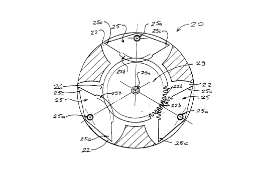
Figure 5 is a cross-sectional view illustrating the inner mechanism of a gear-
actuated embodiment of the invention. In this embodiment, central chamber (26)
houses a drive
member which in this case is a gear wheel (29) connected to the drive stem
(32). The gear wheel
(29) has gear teeth (29b) continuously around its perimeter (notwithstanding
that gear teeth (29b)
are shown only partially in Figure 5. The gripper openings (22) in this
embodiment of the
invention are wide recesses each housing a gripper wing (25) as illustrated in
Figure 5. Each
gripper wing (25) is a substantially planar member rotatably mounted to the
housing (20) by a
gripper wing pin (25a) having an inner central section with gear teeth (25b)
which may engage
the gear teeth (29b) of gear wheel (29), and having two pointed wingtips (25c)
arrayed
substantially symmetrically either side of the corresponding gripper wing pin
(25a).
Having reference to Figure SA, it may be readily seen that when housing (20)
of
the gear-actuated embodiment of present invention has been inserted into the
bore (55, 65) of a
thread protector (50, 60) on a pipe (40), and drive stem (32) is rotated in a
selected direction, one
of the pointed wingtips (25c) of each gripper wing (25) will swing outward
through gripper
openings (22) so as to project beyond the perimeter surface (21), and will
then press into the
comparatively soft material of the inner surface (54, 62) of the thread
protector (50, 60). With
the projecting wingtips (25c) thus engaging the thread protector (50, 60), and
with movement of
pipe (40) being restrained, further rotation of drive stem {32) will urge the
thread protector (50,
60) to rotate relative to the pipe (40). If drive stem (32) is rotated in the
opposite direction, the
other wingtips (25c) or gripper wings (25) will swing out and engage the
thread protector (50,
60). Accordingly, the thread protector (50, 60) may be selectively loosened or
tightened
depending on the chosen direction of rotation of drive stem (32). It will also
be readily seen that
8
CA 02302112 2000-03-27
increased rotation of drive stem (32) enhances the effectiveness of tool (10),
because the outward
extension of wingtips (25c), as well as the force with which they are pressed
into the inner
surface (54, 62) of the thread protector (50, 60), will increase with further
rotation of gear wheel
(29) concurrent with further rotation of drive stem (32).
Figures 3 and 5 illustrate two alternative embodiments of the invention. In
both
embodiments, the rotation of a drive member (28, 29) in the housing (20)
causes a gripping
element (24, 25) to extend beyond the perimeter of the housing to grip the
thread protector and
cause it to rotate. The present invention is not intended to be restricted to
the two embodiments
illustrated. Those skilled in the art may conceive of alternative
configurations which accomplish
the same result by similar means.
The embodiment shown in Figure SA is a slight variant of the gear-actuated
embodiment shown in Figure 5. As may be seen, the gripper wing (25) is
substantially semi-
circular in configuration. The housing (20) includes integral stoppers (23)
which limit the travel
of the gripper wings (25). The stoppers (23) are integral with the housing
(20) and have the
effect of splitting each gripper opening (22) such that each wingtip (25c) is
positioned within a
gripper opening (22). Therefore, in this embodiment, there are 6 gripper
openings (22), for each
wingtip (25c)
Figures 6 through 9 illustrate an alternative embodiment of the present
invention,
namely a combination tool for use in removing thread protectors that have
internal notches or
external splines (or both). In this embodiment, the tools has no moving parts
but is shaped to
engage notches or splines on the thread protector in order to rotate the
thread protector. Figure 6
depicts combination tool (70) positioned for use in removing a thread
protector (50) having
internal notches (57). The thread protector (50) in Figure 6 is also shown as
having splines (58),
and as will be seen shortly, the combination tool (70) may also be used to
remove such a thread
protector by engaging the splines (58). Figure 7 is a section through the
thread protector (50)
more clearly illustrating the notches (57) and splines (58). As will be
readily apparent, thread
protector (50) could have notches (57) only or splines (58) only, and still be
removable using
combination tool (70).
9
CA 02302112 2000-03-27
Referring to Figures 6, 8 and 9, combination tool (70) has a circular ring
(72) with
spline-engaging grooves (72a), plus bracing members (73) which is shown in
cruciform shape
but obviously could be provided in numerous other configurations with equal
utility. The
combination tool (70) also has insert body (74) comprising flange (75), inner
disc (76), and two
or more lugs (78) projecting radially from inner disc (76) and configured so
as to mate with
notches (57) of the thread protector (50).
The combination tool (70) also has drive stems (71) and (79) which are coaxial
with each other as well as with circular ring (72) and inner disc (76). Drive
stem (71), generally
associated with circular ring (72), and drive stem (79), generally associated
with inner disc (76),
have drive sockets (71 a) and (79a) respectively, to facilitate operation of
combination tool (70)
using a conventional socket wrench or similar device. Drive sockets (71 a) and
(79a) may be of
square, hexagonal, or other appropriate configuration to permit use of a
desired style of wrench.
Alternatively, drive stems (71 ) and (79) may have a square, hexagonal, or
other appropriate
external configuration so as to permit engagement thereof with a crescent
wrench or open-end
wrench.
It may be readily seen from Figure 6 that combination tool (70) may be
deployed
such that inner disc (76) enters cylindrical bore (55) of thread protector
(50) and such that lugs
(78) engage notches (58) of thread protector (50). Rotational force may then
be applied to drive
stem (71 ) so as to tighten or loosen thread protector (50) from pipe (40),
according to the
direction of rotation. Similarly, it may be readily seen that combination tool
(70) could be turned
180 degrees from the position shown in Figure 6 and lowered over thread
protector (50) such that
the spline-engaging grooves (72a) of circular ring (72) engage splines (58) of
thread protector
(50), whereupon rotational force applied to drive stem (79) will tighten or
loosen thread protector
(50) as desired.
As will be apparent to those skilled in the art, various modifications,
adaptations
and variations of the foregoing specific disclosure can be made without
departing from the scope
of the present invention.