Note : Les descriptions sont présentées dans la langue officielle dans laquelle elles ont été soumises.
CA 02304174 2000-03-21
WO 99/15065 PCT/US98/19818
-1-
BRUSH CONTAINER WITH LOCKING DEVICE
Technical Field
This invention relates to toilet bowl cleaning brushes and containers for
storing them. More particularly, it relates to sealable and securable
containers for
storing such brushes.
Background Art
Toilet bowls can become stained due to chemicals present in a water supply or
due to residual waste. To remove stains many toilet bowl cleaning products
contain
surfactants applied with a brush. During cleaning, a brush often becomes
soiled and
contaminated with germs. Even after rinsing, there can still be residual waste
on the
brush (or at least the perception that such waste has not been fully rinsed
offj. In any
event the brush will be damp.
As such, toilet bowl brushes are often stored in a container between uses. In
addition, some containers are provided with a liquid disinfectant formulated
to
sanitize a brush between uses. Such brushes and their containers are
preferably stored
on the floor near a toilet.
However, disinfectants may contain ingredients which are harmful if ingested.
Very young children may not be able to recognize that a toilet brush and its
container
contain harmful products. Thus, in households with young children such
containers
are usually stored in locked cabinets or closets (rather than the preferred
site, next to a
toilet).
While various entry deterent devices have been developed (e.g. in the
pharmaceutical container field), applying these concepts to toilet brush
container
systems can lead to unnecessarily complex designs, an insufficient seal and
thus
spillage or odors, and/or an ineffective locking device. Alternately, this
might require
a user to touch the t~ of the container in order to unlock or lock the
container. This
CA 02304174 2000-03-21
WO 99/15065 PCTIUS98/19818
-2-
may be objectionable in this application as brush drippage might have
contaminated
the top portion of a container during insertion or extraction.
It can therefore be seen that a need exists for an improved entry deterrent
device for a toilet bowl brush/container system.
BRIEF SUMMARY OF THE INVENTION
In one aspect the invention provides a combined brush and storage container
system. The system includes a container having an upper edge, an internal
storage
cavity extending downward from the edge to define a peripheral cavity sidewall
and a
ledge formed on the sidewall. A radially resilient collar is disposed over the
ledge and
has first and second ends and a latch extending radially inward.
A key (preferably a ring-like skirt) is mounted on the upper edge over the
collar for maintaining the collar within the cavity. A brush having an upper
handle, a
radially extending support below the upper handle, and a lower brush portion
below
the support is provided. When the brush portion is inserted in the container
the
support is supported over (preferably on) the ledge.
Relative movement of the first and second collar ends from a first position to
a
second position can drive the latch radially outward from a position blocking
removal
of the brush. Return of the ends to the first position from the second
position can
cause the latch to move radially inward into a locking position. The collar
and cavity
are preferably cylindrical.
In one aspect the collar includes oppositely facing inner and outer surfaces
and
the latch extends radially inward from the inner surface. In this aspect, the
key is
mounted for rotational movement around the edge and includes a lower portion
extending downward into the cavity between the collar and the sidewall, the
lower
portion having an internal surface. The collar external surface and lower
portion
internal surface each are a limiting surface. A first of the limiting surfaces
forms a
foot extension extending radially toward the other. There is also a recess in
the other.
CA 02304174 2000-03-21
WO 99/15065 PCT/US98119818
-3-
In this aspect, when the key is in a first placement the foot is misaligned
with
the recess and contacts the first limiting surface (limiting the first and
second ends to
the first position). When the key is rotated from the first to a second
placement, the
foot is aligned with the recess and the first and second ends of the collar
can be moved
relative to each other. The collar external surface can be a first of the
limiters
circumferentially adjacent the latch. Also, preferably, the collar external
surface is the
first limiting surface and the key internal surface is the second limiting
surface.
In another aspect, there are two latches extending inward from opposite sides
of the collar, two recesses formed on opposite sides of the collar and two
feet
extending from opposite sides of the lower portion. In yet another aspect the
first and
second ends are essentially 90 circumferential degrees from the two latches.
In another embodiment, an alignment post extends axially downwardly from
the collar opposite the first and second ends and the ledge forms an aperture
for
receiving the post.
1 S The container has an opening in the sidewall adjacent the first and second
ends, the collar including first and second tabs which are part of the first
and second
ends, respectively. The first and second tabs extend radially outward through
the
opening to provide a pinch operated locking system. In this regard, the first
and
second ends overlap such that when the first end is pinched toward the second
end it
expands the collar, thus freeing the brush.
In one other aspect, the key and the container include first and second
exterior
markings, respectively, the markings being aligned when the latch does not
inhibit the
removal of the brush.
The brush support is preferably a wall and disinfectant fluid is preferably
placed in the container cavity.
The invention also includes a method of storing such a brush. One positions
the brush in the above described container.
It will be appreciated from the discussion below that the present invention
provides an assembly for storing a toilet bowl cleaning brush where the
bristles/pad of
CA 02304174 2000-03-21
WO 99/15065 PCTIUS98/19818
the brush are immersible in a disinfectant between use. A user can pick up the
assembly by the brush handle and transport the entire assembly to another
place.
In addition, a dependable sealingllocking device is provided which requires
several affirmative steps to unlock the container, thereby making it difficult
for a
young child to access the disinfectant therein. Moreover, a brush locked with
the
inventive system can be unlocked without touching the top of the container.
A primary object of the invention is to provide a system of the above kind
which requires a number of affirmative actions to open, thus rendering the
opening
process relatively difficult for a young child (yet simple for most adults).
Another object of the invention is to provide a storage container for a
cleaning
brush in which the container is designed to store both the brush and a
disinfectant with
reduced risk of spillage.
Another object of the invention is to provide a system of the above kind which
inhibits odors from escaping the container.
I S Another object of the invention is to provide a system of the above kind
which
is comprised of few parts, which is inexpensive to produce, and which is easy
for a
consumer to use.
Still other objects and advantages of the present invention (e.g. methods for
using these systems) will become apparent from examination of the
specification and
claims which follow.
BRIEF DESCRIPTION OF THE DRAWINGS
Fig. 1 is perspective view of an embodiment of the inventive system;
Fig. 2 is an exploded perspective view of the system of Fig. 1;
Fig. 3 is a cross-sectional view taken along line 3-3 in Fig. 1;
Fig. 4 is an enlarged exploded view of a portion of the locking mechanism of
Fig. 1;
Fig. 5 is a cross-sectional view taken along 5-5 of Fig. 3 with a locking key
in
a locking co~guration;
CA 02304174 2000-03-21
WO 99/15065 PCT/US98/19818
-5-
Fig. 6 is a view similar to Fig. 5, albeit with the locking key in an
unlocking
configuration;
Fig. 7 is a view similar to Fig. 6 with a collar in an expanded position;
Fig. 8 is a cross-sectional view taken along line 8-8 of Fig. 7;
Fig. 9 is a cross-sectional view taken along line 9-9 of Fig. 5;
Fig. 10 is a cross-sectional view taken along Line 10-10 of Fig. 6;
Fig. 11 is a cross-sectional view taken along line 11-11 of Fig. 7; and
Fig. 12 is a cross-sectional view taken along line 12-12 of Fig. 4.
Modes for Carrying Out Invention
Fig. 1 shows the combined brush and storage system of the present invention
(generally 10). Referring also to Figs. 2, 3 and 4, the system 10 generally
includes
four separate components or assemblies including a container 12, a locking key
ring
14, a locking collar 16 and a brush assembly 18. Unless otherwise specified,
all of the
components and assemblies of the system are preferably made of plastic such as
ABS
of polyethylene.
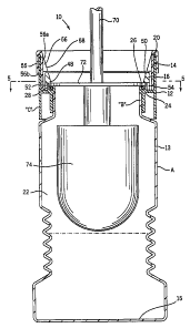
As best seen in Fig. 3, container 12 includes a floor wall 15 and a
cylindrical
peripheral cavity sidewall 13 which extends upwardly from wall I S to an upper
edge
20. Walls 13 and I S together define a storage cavity 22. Below edge 20 a
circumferential flange 24 extends radially inwardly forming a ledge 26. O-ring
28 is
positioned on ledge 26 and is preferably made of rubber. Wall 13 has an
opening 30
between ledge 28 and edge 20 see Figs. 1 and 4). Opposite opening 30 a post
aperture 19 extends downward through ledge 26. Wall 13 also forms first and
second
apertures 90, 91 which pass through opposing sides of wall 13. Each aperture
90, 91
is preferably formed approximately 90 circumferential degrees from aperture 19
and
each is approximately twice as long as opening 30.
Referring to Figs. 3, 4 and 5, collar I6 includes a radially resilient band
having
an inner surface 32, an outer surface 34, and first and second ends 36 and 38,
respectively. Ends 36 and 38 extend past each other and are interleaved see
Fig. 4).
CA 02304174 2000-03-21
WO 99115065 PCT/US98119818
-6-
First and second tabs 40, 42, respectively, extend radially outwardly as part
of second
ends 36, 38, respectively. Finger pads 44 and 45 may be provided on each of
tabs 40
and 42. Opposite tabs 40 and 42 a single alignment post 46 extends downwardly
from
collar 16. Post 46 is formed so that it fits snugly within aperture 19. Collar
16 may
be formed of resilient metal (or if desired a resilient plastic).
First and second latches 48, 50 extend radially inward from opposite sides of
surface 32 and each is preferably positioned so as to be approximately 90
circurnferential degrees from post 46. Just below latches 48 and S0, external
surface
34 define two recesses 52, 54. In the figures recesses 52 and 54 are
illustrated as
openings.
Referring to Figs. 5 and 7, a diameter D", where n is 1 or 2, is defined by
the
distal edges of latches 48 and 50 and diameter Dn can be manipulated by
changing the
spacial relationship between tabs 40 and 42 (i.e. ends 36 and 38). In
addition, a
diameter Dm, where m is 3 or 4, is defined by collar outer surface 34 taken
through
latches 48 and 50 and diameter Dm is also manipulated via tabs 40 and 42. In a
relaxed or first position see Fig. 5), ends 40 and 42 are separated and
diameter D" is
D~ while diameter Dm is D3. However, when tabs 40 and 42 are pinched together
into
second position see Fig. 7), latches 48 and 50 are forced radially outwardly,
diameter
D" is D2 where D2 is greater than D1 and diameter Dm is D4 where D4 is greater
than
D3.
Refen-ing still to Figs. 3, 4 and 5 and also to Fig. 12, key 14 is in the form
of a
slip ring or skirt mounted over upper edge 20 having external and internal
walls 55
and 56, respectively. Wall 55 defines internal and external surfaces 92, 93
(see Fig.
9). Wall 56 defines an internal surface 58 and includes a top portion 56a and
a bottom
portion 56b. Portion 56a slops radially inwardly and downwardly while portion
56b
is essentially vertical.
Two legs 60, 62 extend downwardly from opposite sides of portion 56a and
radially inwardly from portion 56b. A separate foot 64, 66 extends radially
inwardly
from the distal end of each of legs 60 and 62. Feet 64 and 66 are sized such
that they
are receivable in recesses 52 and 54 when the key is aligned to permit this.
The distal
CA 02304174 2000-03-21
WO 99/15065 PCT/US98/19818
_7-
edges of feet 64 and 66 define a diameter DS which is essentially equal to
diameter D3
see Fig. 5). Approximately 90 circumferential degrees from leg 60, lower
portion
56b forms an opening 68 which is approximately twice as long (in the
circumferential
direction) as opening 30.
First and second securing feet 95, 96 extend radially inward from the distal
edge of internal surface 92. Foot 95 is circumferentially aligned with foot 64
while
foot 96 is circumferentially aligned with foot 66. Feet 95 and 96 are sized so
as to be
snugly receivable within apertures 90 and 91 but to be approximately half as
long (in
the circumferential direction) as apertures 90 and 91.
Brush assembly 18 has an upper handle 70, a radially extending generally
disk-like support wall 72 sized to rest on o-ring 28 and then on ledge 26, and
a lower
bristle or pad section 74. Alternatively, other brushing means can be used. A
diameter D6 see Fig. 2) of wall 72 is greater than diameter D~ but less than
diameter
D2.
Disinfectant/cleaning fluid can be added to the cavity 13 to cover bristles
57.
Numerous known fluids of this type can be used. One such fluid is .4% alkyl
dimethyl benzyl ammonium chloride, .O1% of a dye such as Acid Blue, and the
remainder water. If desired, a portion of the water can be replaced with a
surfactant
compatible with the disinfectant to provide 1% non-ionic surfactant (e.g. an
ethoxylated alcohol such as L-24-9 from Huntsman). Also, a perfume oil can
also be
added (e.g. .1%). Other disinfectants may also be used.
Referring to Fig. 3, when assembled, post 46 is received in aperture 19 see
Fig. 8) and collar 16 rests on ledge 26 with tabs 40 and 42 aligned with and
extending
radially out of opening 30. (See Figs. 1, 2 and 5). Key 15 straddles edge 20
with
lower portion 56b extending between wall 13 and collar 16 above ledge 26 and
with
opening 68 aligned with opening 30. Outer surface 34 faces internal surface 58
of
portion 56b and feet 95 and 96 are received within apertures 90 and 91,
respectively.
Once feet 95 and 96 are secured in apertures 90 and 91, key 14 is axially
locked onto
edge 20 and maintains collar 16 thereunder. Nevertheless, key 14 can be
rotated
CA 02304174 2000-03-21
WO 99/15065 PCT/US98/i9818
_g_
through an angle (e.g. 20E} about edge 20. During rotation feet 95 and 96
slide along
the lengths of apertures 90 and 91.
First and second alignment markers 41 and 43 see Figs. 1 and 2) are provided
on external and easily observable surfaces of container 12 and key 14. Markers
41
and 43 are aligned when feet 64 and 66 are adjacent recesses 52 and 54 and are
misaligned when feet 64 and 66 are not aligned with recesses 52 and 54,
respectively.
Referring to Fig. 6, in order to secure brush 74 inside container 12, key 14
is
rotated about edge 20 until feet 64 and 66 are aligned with recesses 52 and 54
(i.e.
markers 41 and 43 are aligned). See Figs. 2, 6 and 10). When key 14 is
rotated, feet
95 and 96 slide along the circumferential lengths of recesses 90 and 91. With
recesses
52, 54 and feet 64 and 66 aligned, one can push on opposite sides of tabs 40
and 42 as
illustrated by arrows 76 and 78 in Fig. 7 forcing tabs 40 and 42 together.
When tabs
40 and 42 are pinched together, latches 48 and 50 are forced radially outward
and
diameter D" is expanded to D2 see Figs. 7 and 11). Because feet 64 and 66 are
aligned with recesses 52 and 54, they are received therein and do not impede
expansion of collar 16.
When latches 48 and 50 are forced radially outward, because wall 72 diameter
D6 is less than diameter D2, section 74 can be inserted into container 12 such
that wall
72 rests on o-ring 78. Next, tabs 40 and 42 are released, collar 16
resiliently contracts
back to its original position with latches 48 and 50 above o-ring 28 defining
diameter
D1. Latches 48 and 50 "step on" support wall 72 and secure the wall in place.
To ensure that latches 48 and 50 are not inadvertently removed from this
"locking position", key 14 can be rotated about edge 20 until feet 64 and 66
are
misaligned with recesses 52 and 54 (i.e. markings 41 and 43 are misaligned)
com are
Figs. 5 and 9 with Fig. 6). When key 14 is in this second configuration, feet
64 and
66 contact outer surface 34 and restrict expansion of collar 16 such that
diameter Dn is
limited to D~ and Dm is limited to D3. Thus, when markers 41 and 43 are
misaligned,
if pressure is applied to tabs 40 and 42, radially outward movement of latches
48 and
SO is impeded and latches 48 and 50 secure section 74 within container 12.
CA 02304174 2000-03-21
WO 99/15065 PCT/I1S98/19818
-9-
When assembly 18 is again to be used, one picks up system 10 via handle 70
and transports the entire system to an area for use. One rotates key 14 from
the
locking configuration (see Figs. 1, 5 and 9) to the unlocked configuration see
Figs. 2,
6 and 10) with markings 41 and 43 aligned. Next, one forces tabs 40 and 42
from the
locking position see Figs. 1 and 6) to the unlocking position see Figs. 2 and
7) and
removes assembly 18 from container 12 for use.
Industrial Applicability
The present invention is comprised of few parts, is inexpensive to produce,
and which is easy for a consumer to use. What has been described above are the
preferred embodiments of the present invention. Other embodiments are also
within
the intended scope of the claims. For example, while the system is described
as one
wherein the outer surface of collar 16 forms a recess and the internal surface
of key 14
forms legs and feet, these elements could be reversed. For example, the legs
and feet
or, for that matter, just feet, could be formed on the outer surface of collar
16 and the
recesses could be formed in the internal surface of key 14.
In addition, the invention is meant to include a system wherein the key does
not rotate to lock the collar in a single configuration. Moreover, the system
may
include more than two latches or the latches may be located at different
circumferential positions with respect to each other or with respect to tabs
40 and 42.
As such, the claims which follow should be looked to in order to judge the
full scope
of the invention.