Sélection de la langue

Search

Sommaire du brevet 2309568 

Énoncé de désistement de responsabilité concernant l'information provenant de tiers

Une partie des informations de ce site Web a été fournie par des sources externes. Le gouvernement du Canada n'assume aucune responsabilité concernant la précision, l'actualité ou la fiabilité des informations fournies par les sources externes. Les utilisateurs qui désirent employer cette information devraient consulter directement la source des informations. Le contenu fourni par les sources externes n'est pas assujetti aux exigences sur les langues officielles, la protection des renseignements personnels et l'accessibilité.

Disponibilité de l'Abrégé et des Revendications

L'apparition de différences dans le texte et l'image des Revendications et de l'Abrégé dépend du moment auquel le document est publié. Les textes des Revendications et de l'Abrégé sont affichés :

  • lorsque la demande peut être examinée par le public;
  • lorsque le brevet est émis (délivrance).
(12) Demande de brevet: (11) CA 2309568
(54) Titre français: OBTURATEUR DE DISTRIBUTEUR DE LIQUIDES
(54) Titre anglais: FLUID DISPENSING CLOSURE
Statut: Morte
Données bibliographiques
(51) Classification internationale des brevets (CIB):
  • B65D 47/14 (2006.01)
(72) Inventeurs :
  • BEAVER, JEFFREY L. (Etats-Unis d'Amérique)
(73) Titulaires :
  • RIEKE CORPORATION (Etats-Unis d'Amérique)
(71) Demandeurs :
  • RIEKE CORPORATION (Etats-Unis d'Amérique)
(74) Agent: SMART & BIGGAR
(74) Co-agent:
(45) Délivré:
(22) Date de dépôt: 2000-05-26
(41) Mise à la disponibilité du public: 2000-11-27
Requête d'examen: 2000-05-26
Licence disponible: S.O.
(25) Langue des documents déposés: Anglais

Traité de coopération en matière de brevets (PCT): Non

(30) Données de priorité de la demande:
Numéro de la demande Pays / territoire Date
60/136,152 Etats-Unis d'Amérique 1999-05-27
09/576,566 Etats-Unis d'Amérique 2000-05-22

Abrégés

Abrégé anglais


A fluid dispensing closure which incorporates a
dispensing valve to control fluid flow through the closure
and a vent passageway to vent air into the container as
necessary. The closure includes a dispenser spout offset
from the axis of the closure and capable of mating
engagement with a receiving container. The dispenser spout
has a fluid passageway with a spring-biased ball valve
seated therein. A vent passageway is also formed in the
closure which includes a gravity loaded ball valve to close
the vent passageway according to the position of the
closure. A removable overcap sealingly encloses the
dispenser spout and vent to capture any fluid leakage.

Revendications

Note : Les revendications sont présentées dans la langue officielle dans laquelle elles ont été soumises.


CLAIMS

Claim 1. A dispensing closure adapted to control the flow
of fluid from a container, said dispensing closure
comprising:
a housing adapted to be attached to the container;
a nozzle extending from said housing in fluid
communication with the container, said nozzle having a
valve assembly for selectively preventing fluid flow
through said nozzle; and
a vent formed in said housing proximate said nozzle,
said vent including a vent opening and a valve member for
selectively closing said vent opening.

Claim 2. The dispensing closure as defined in claim 1 and
further comprising a cap detachably mounted to said
closure, said cap enclosing said nozzle and said vent
opening to selectively prevent fluid leakage from said
closure.

Claim 3. A dispensing closure for selectively dispensing
fluid from a container into a receiving system, the
dispensing closure comprising:
a housing having an inner threaded surface for
threaded attachment to the container, and an outer surface;
a dispensing nozzle contained within the housing and
having a dispensing end and a receiving end,
a valve assembly for selectively dispensing fluid
through the nozzle, the valve assembly being contained
within the dispensing end of the nozzle;

7


a vent contained within the housing at a location
displaced from the nozzle.

Claim 4. The dispensing closure as described in claim 3,
wherein the dispensing nozzle is laterally displaced from
the vertical central axis of the housing.

Claim 5. The dispensing closure as described in claim 4,
wherein the valve assembly contained within the dispensing
nozzle comprises:
a circular aperture at the dispensing end of the
nozzle,
a valve ball sized to fit sealingly within the
circular aperture, and
a coil spring anchored within the receiving end and
the valve ball, the valve ball being biased against and
thereby selectively sealing the circular aperture.

Claim 6. The dispensing closure as described in claim 3,
wherein the vent comprises an opening and a valve member
for selectively closing the vent opening.

Claim 7. The dispensing closure as described in claim 6
wherein the valve member consists of a vent ball that rests
upon the opening within the vent.

Claim 8. The dispensing closure as described in claim 3,
further comprising a cap detachably mounted to the closure,
the cap enclosing both the nozzle and the vent.


8


Claim 9. A dispensing closure for selectively dispensing
fluid from a container into a receiving system, the
dispensing closure comprising:
a housing having an inner threaded surface for
threaded attachment to the container, and an outer surface,
the housing being substantially cylindrical about a central
vertical axis;
a dispensing nozzle contained within the housing and
having a dispensing end and a receiving end, the nozzle
being laterally displaced from the vertical central axis of
the housing;
a valve assembly for selectively dispensing fluid
through the nozzle, the valve assembly being contained
within the dispensing end of the nozzle and having: a
circular aperture at the dispensing end of the nozzle; a
valve ball sized to fit sealingly within the circular
aperture; and a coil spring anchored within the receiving
end and the valve ball, such that the valve ball is biased
by the spring against the circular aperture, thereby
sealing the aperture; and
a vent contained within the housing at a location
displaced from the nozzle, the vent comprising an opening
and a valve member for selectively closing the vent
opening.

Claim 10. The dispensing closure as described in claim 9,
wherein the valve member of the vent consists of a vent
ball that rests upon the opening within the vent.

Claim 11. The dispensing closure as described in claim 9,
further comprising a cap detachably mounted to the closure,
the cap enclosing both the nozzle and the vent.


9


Claim 12. The dispensing closure as described in claim 9,
wherein the dispensing nozzle is integrally molded within
the housing, and wherein the vent is formed within the
housing at a location displaced apart from the dispensing
nozzle.


10
Description

Note : Les descriptions sont présentées dans la langue officielle dans laquelle elles ont été soumises.


CA 02309568 2000-OS-26
940-3055
FLUID DISPENSING CLOSURE
Relation Applications
This application claims priority from U.S. Provisional
Application No. 60/136,152 filed on May 27, 1999.
Background Of The Invention
I. Field of the Invention
This invention relates to a fluid dispensing closure
for selectively dispensing fluids such as juices into a
desired container and, in particular, to a dispenser
matingly engageable with a receiving container and
including, in combination, a spring-biased dispensing valve
and a vent valve.
II. Description of the Prior Art
A variety of closures have been developed for
selective control of fluid flow from a container. The most
common closure incorporates a valve which may be rotated or
otherwise manually opened and closed to dispense fluid from
the container. The dispensing closure is typically
situated near the bottom of the container allowing gravity
to force fluid through the closure.
However, commercial beverage dispensers incorporate
mechanical dispensing means associated with the housing.
Examples include milk and juice dispensers which have
external dispensing systems. Bulk beverage containers are
internally replaced as needed. These containers must be
capable of preventing fluid leakage during transport while
also preventing contamination of the contents and
dispensing closure. In order to ensure smooth dispensing
#19248 v2 - App. for Fluid Dispensing Closure


CA 02309568 2000-OS-26
of the fluid, a venting system allowing air to replace the
dispensed liquid should be included in the dispensing
closure. The closure will cooperate with the dispensing
machine to facilitate on demand pouring of fluids such as
juice or milk.
III. Summary of the Present Invention
The present invention overcomes the disadvantages of
the prior known dispensers by providing a dispensing
closure which incorporates a spring-biased dispensing valve
and vent valve within the confines of the closure.
The fluid dispensing closure of the present invention
includes a substantially cylindrical base adapted to be
threadably attached to the container. A cylindrical
dispensing spout extends from the base. The dispensing
spout is offset from the axis of the base but provides
fluid communication with the container. A valuing member
is disposed within the dispenser spout to control fluid
flow therethrough. In a preferred embodiment the valuing
member comprises a spring-biased ball seated within the
dispenser spout to control fluid flow. The dispenser spout
is offset from the central axis of the closure to
accommodate a vent valve. The vent includes a vent
passageway in communication with a vent aperture. A ball
captured within the passageway selectively closes the vent
aperture according to the position of the closure to
selectively facilitate venting of the dispensing closure.
The dispenser includes means for receiving a removable
overcap which encloses the dispensing spout and vent to
capture any potential fluid leakage. The overcap includes
a rim bead adapted to engage an annular groove extending
around the spout and vent. The cap can be simply removed
2


CA 02309568 2000-OS-26
and attached by flexing the cap. The dispenser spout is
provided with an 0-ring seal to facilitate sealing
engagement with a receiving container. Upon insertion of
the spout into the receiver container, the spring-biased
ball valve is displaced from its valve seat allowing fluid
to flow through the spout. Gravity will cause the vent
ball to close off the vent aperture thereby ensuring that
fluid flows through the spout and not the vent.
Other objects, features and advantages of the
invention will be apparent from the following detailed
description taken in connection with the accompanying
drawings.
IV. Brief Description of the Drawing
The present invention will be more fully understood by
reference to the following detailed description of a
preferred embodiment of the present invention when read in
conjunction with the accompanying drawing, in which like
reference characters refer to like parts throughout the
views and in which:
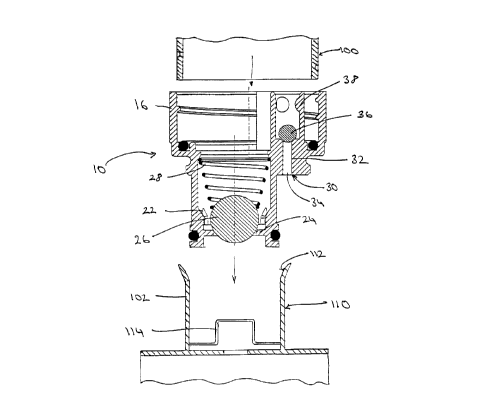
FIGURE 1 is an exploded view of the dispensing closure
in conjunction with a fluid container and a dispensing
mechanism;
FIGURE 2 is a perspective view of a fluid dispensing
closure embodying the present invention, and having a cut-
away section showing the internal closure construction;
FIGURE 3 is a bottom perspective view of the closure;
and
FIGURE 4 is a cross-sectional view thereof with the
cap removed.
3


CA 02309568 2000-OS-26
V. Detailed Description of A Preferred
Embodiment of the Present Invention
Referring first to Figures 1, 2 and 4, there is shown
a closure 10 for selectively dispensing a fluid from a bulk
container 100 into a dispensing system 110. In a preferred
embodiment, the closure 10 is designed to dispense a liquid
such as juice from a replaceable bulk container 100. The
closure 10 must prevent fluid leakage during transport and
storage of the bulk container 100 but must be compatible
with the dispensing system 110 for dispensing of the fluid
contents.
The closure 10 of the present invention includes a
housing 12 adapted to be threadably secured to a neck 102
of the container bottle 100. The housing 12 includes an
annular extension surface 14 having a plurality of
protrusions 16 to facilitate gripping during attachment to
the container 100.
Extending from the housing 12 is a fluid nozzle 18
through which the fluid is dispensed. The nozzle 18 has a
tubular configuration smaller in diameter than the housing
12 and, as shown in Figures 1-3 is off-set from the central
vertical axis of the closure 10. The nozzle 18 is
configured to matingly engage the dispensing system 110 as
will be subsequently described. The nozzle 18 includes an
inner fluid passageway 20 within which is seated a valve
assembly 22 for controlling fluid flow through the nozzle
18. The valve assembly 22 has a valve seat 24 and a
spring-biased valve ball 26 which seals within the valve
seat 24 to block fluid flow. A coil spring 28 biases the
ball 26 towards the closed position against the seat 24.
Also disposed within the housing 12 is a vent 30 which
allows air to replace the dispensed fluid within the
4


CA 02309568 2000-OS-26
container 100. The vent assembly 30 is molded directly
within the closure 10 in close proximity to the fluid
nozzle 18. The vent 30 comprises a cylindrical passageway
32 in communication with a vent throughbore 34. A vent
ball 35 is captured within the cylindrical passageway 32
for movement between a closed position seated within the
throughbore 34 and an open position allowing flow through
the vent 30. A plurality of protrusions 38 within the
passageway 32 keeps the vent ball 36 within the vent
passageway 32. The weight of the vent ball 36 serves to
close the throughbore 34 by sealing the top of the
cylindrical passageway 32. However, as fluid is dispensed
from the container 100, a vacuum builds within the housing
12 until the force is sufficient to lift the vent ball 36
from the valve seat 32. This unseating of the vent ball 36
causes air to vent through the closure 10. This enables the
fluid to dispense smoothly through the closure 10.
As best shown in Figures 1 and 2, a containment cap 40
is selectively attached to the closure 10. The closure 10
includes an annular rim 42 which encircles not only the
nozzle 18 but also the vent passageway 34. The cap 40 has
an annular bead 44 on an inside rim of the cap 40, which is
received within the rim 42. With the cap 40 positioned on
the closure 10, contaminants are kept from the dispensing
nozzle 18 prior to use. Additionally, because the cap 40
encircles both the nozzle 18 and the vent assembly 30, any
fluid leakage from either passageway will be captured
within the cap 40.
The closure 10 is designed to selectively dispense
fluid from a container 100 into a dispensing system 110.
Referring to Figure 1, the closure 10 is secured to the
container 100 upon filling of the container 100 at the


CA 02309568 2000-OS-26
supplier. During transport and storage, the cap 40 is
maintained on the closure 10. Prior to use, the cap 40 is
removed and the nozzle 18 is inserted into the dispensing
system 110. The nozzle 18 sealingly engages a receptor
112, which includes means 114 for pushing the valve ball 26
away from the seat 24. The dispensing of fluid from the
container 100 is now controlled by the dispensing system
110. Once the container 100 has been emptied, the
container 100 and its closure 10 are removed from the
dispensing system 110 allowing the valve ball 26 to seat,
thereby closing valve 22. This prevents any escaping of
residual fluid as the empty containers 100 are being
replaced with full ones.
The foregoing detailed description has been given for
clearness of understanding only and no unnecessary
limitations should be understood therefrom as some
modifications will be obvious to those skilled in the art
without departing from the scope and spirit of the appended
claims.
What is claimed is:
6

Dessin représentatif
Une figure unique qui représente un dessin illustrant l'invention.
États administratifs

Pour une meilleure compréhension de l'état de la demande ou brevet qui figure sur cette page, la rubrique Mise en garde , et les descriptions de Brevet , États administratifs , Taxes périodiques et Historique des paiements devraient être consultées.

États administratifs

Titre Date
Date de délivrance prévu Non disponible
(22) Dépôt 2000-05-26
Requête d'examen 2000-05-26
(41) Mise à la disponibilité du public 2000-11-27
Demande morte 2004-10-07

Historique d'abandonnement

Date d'abandonnement Raison Reinstatement Date
2003-10-07 R30(2) - Absence de réponse
2004-05-26 Taxe périodique sur la demande impayée

Historique des paiements

Type de taxes Anniversaire Échéance Montant payé Date payée
Requête d'examen 400,00 $ 2000-05-26
Le dépôt d'une demande de brevet 300,00 $ 2000-05-26
Enregistrement de documents 100,00 $ 2000-07-27
Taxe de maintien en état - Demande - nouvelle loi 2 2002-05-27 100,00 $ 2002-05-03
Taxe de maintien en état - Demande - nouvelle loi 3 2003-05-26 100,00 $ 2003-05-05
Titulaires au dossier

Les titulaires actuels et antérieures au dossier sont affichés en ordre alphabétique.

Titulaires actuels au dossier
RIEKE CORPORATION
Titulaires antérieures au dossier
BEAVER, JEFFREY L.
Les propriétaires antérieurs qui ne figurent pas dans la liste des « Propriétaires au dossier » apparaîtront dans d'autres documents au dossier.
Documents

Pour visionner les fichiers sélectionnés, entrer le code reCAPTCHA :


Pour visualiser une image, cliquer sur un lien dans la colonne description du document. Pour télécharger l'image (les images), cliquer l'une ou plusieurs cases à cocher dans la première colonne et ensuite cliquer sur le bouton "Télécharger sélection en format PDF (archive Zip)" ou le bouton "Télécharger sélection (en un fichier PDF fusionné)".

Liste des documents de brevet publiés et non publiés sur la BDBC .

Si vous avez des difficultés à accéder au contenu, veuillez communiquer avec le Centre de services à la clientèle au 1-866-997-1936, ou envoyer un courriel au Centre de service à la clientèle de l'OPIC.


Description du
Document 
Date
(yyyy-mm-dd) 
Nombre de pages   Taille de l'image (Ko) 
Description 2000-05-26 6 237
Dessins représentatifs 2000-11-16 1 14
Abrégé 2000-05-26 1 21
Revendications 2000-05-26 4 113
Dessins 2000-05-26 2 77
Page couverture 2000-11-16 1 39
Correspondance 2000-06-30 1 2
Cession 2000-05-26 2 80
Cession 2000-07-27 2 109
Correspondance 2000-08-30 2 90
Cession 2000-05-26 4 170
Correspondance 2000-09-26 1 1
Poursuite-Amendment 2003-04-07 4 196