Note : Les descriptions sont présentées dans la langue officielle dans laquelle elles ont été soumises.
CA 02310974 2001-07-09
Specification
Summary
This invention relates to a compact and lightweight electric booster
controlled by
an innovative chain strain sensor. The booster may allow a wide range of
existing
high efficiency power drills to be installed in minutes on any rigid or
suspended
derailleur bicycles. The unique function of the booster is to efficiently
assist
the rider when he (she) needs to pedal on steep climbs. For all other riding
events, such as flat or shallow rate pedaling, or downhill coasting, the
booster
sensor may be switched "OFF" from a handlebar control to not alter the general
feeling and handling of a regular bicycle.
CA 02310974 2001-07-09
Back ound
A preliminary search on the Canadian, American and European patent database
web sites has identified several bicycle booster concepts of interest. The
most
relevant one was found to be the Canadian patent #CA 2146284 dated April 4
1995 which refers to "Bicycle; Chain Strain Sensing Sprocket Mechanism". This
device provides an automatic control of a booster by sensing of the bicycle
chain
tension similar to the present application. However, a more detailed
examination
revealed that, unlike the present application which provides full
compatibility with
derailleur bikes, this patented device is limited to non derailleur bicycles
only as
it is attached to the frame seat and chain stays without any capability to
fallow the
chain lateral motions that normally occur when the rider shifts gears on any
derailleur bike. Besides, no manually operated sensor disconnector that allows
straigl~teni~g of the chain upper string to mi~ir~i~e friction is provided for
the
riding events that do not require booster operation. The only ON/OFF switch
that
was referred to in this patent description was used to control the booster
through
the motor throttle, not through the chain strain sensor like the present
application
does.
Another finding of interest was the American patent US5758735 dated 199&06-
02 that refers to a " High performance bicycle propulsion". This concept also
provides a chain tension sensor of a sprocket idler type. However, unlike the
present application which is entirety mechanical, the tension signal is
converted
into an electric signal through strain gage instrumentation and again, this
sensing
device is suitable to non derailleur bikes only as it is rigidly mounted on
the
frame.
Another fording of interest was the American patent US 6,062,329 filed in
April
3,1995. "Pedal Bicycle having an Auxiliary Power Means" which discloses a
booster power train that uses an auxiliary chain to drive one of the existing
sprockets of the bike rear hub like the present application does. However,
unlike
the present application which refers to a complete chain J sprocket
transmission,
the concept refers to transmission of a gear box type to achieve the gear
ratio
required by the booster.
Another findurg of interest was the European patent EP 1 097 8b3 A2 tiled in
November 7, 2000 "Electric Power Assist Bicycle" which discloses a chain
sprocket transmission like the present application does. However, unlike the
present application which refers to chain transmission using the rear hub's
largest
cog, the concept refers to a chain transmission using one of the bicycle front
cogs.
At this point, no patent related to the integration of a power drill for a
bicycle
booster was found.
CA 02310974 2001-09-27
Brief Description of the Drawings
FIG 1 is a perspective view of the overall booster equipment.
FIG 2 is a schematic that illustrates the basic functions of the booster
control and sensing
unit. The front view was chosen to clarify the features that provide booster
compatibility
with derailleur bicycles.
FIG 3 is a side view showing some details that are more specific to the
sensing and
control unit.
FIG 4 is a set of side views representing the three possible modes of
operation of the
sensing and control unit:
View A depicts the device attitude when the control switch is set "ON" and no
booster assistance is required by the rider (rider coasting or not pedaling
hard).
View B depicts the device attitude when the control switch is set "ON" and
maximum booster assistance is required by the rider (rider pedaling hard).
View C depicts the device attitude when the control switch is set "OFF" by the
rider to
deactivate the booster sensor in order to minimize chain friction (regular
bicycle mode).
FIG 5 is a side view showing the power train configuration of the booster.
FIG 6 illustrates the versatility of the booster interface to accommodate
various bike
frames:
View A depicts the power train installation on a road bicycle.
View B depicts installation on a mountain bike with rear suspension.
FIG 7 depicts the possible configurations of the power tool trigger control
system using a
cam shaft located at the booster end of the chain strain sensing cable.
View A depicts the sensor cable mounted in the "pushing way".
View B depicts the sensor cable mounted in the "pulling way".
FIG 8 is an overall view of the housing of a possible interface when a power
drill is to be
used for a booster motor.
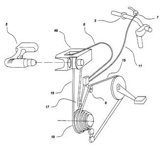
C7~ 02310974 2001-07-09
Red to FIG 1, the )~ooater equipm~t is campoaed of a co~rnl and chain
sensing device having an idler sprocket (9) installed at the upper string
paetion
ofthe bicycle chain (15). The device sends the chain strain signal through a
bicycle cable (8) (referred to as the sensor cable) to the trigger of an
electric motor
S like the powtr drill (5). The dwice is controlled by a ON /OFF switch (7)
mounted on the handlebar (3) through another bicycle cable (11) (referred to
as
the control cable). The device also includes an idler sprocket tensioner (17)
to
prevent the booster chain ( 16) ~ derailing when ttte booster is in operation.
The booster chain (16) drives permanently the largest (inner) cog of the
bicycle
rear hub (19). The rear derailleut shifter is set to allow shifting from the
3rd gear
only in order to prevent possible interference between the booster chain (16)
and
the bicycle chain (15). The chain (16) is mountod on a clutch unit in the
booster
housing (49). The function of the clutch unit is to disconnect the power drill
(5)
motor from the bicycle rear hub ( 19) to minimize friction when the rider
pedals
with the booster switched OFF, or when the rider pedals faster than the
booster
motor spins.
Referring to FIG Z, the control and sensing device is secured on the right
hand
seat stay (1) of the bicycle. The device is &ee to rotate around a pivot axis
(12)
allowing the idler sprocket (9) to follow any lateral motion of the bicycle
chain
(15) when the rider shifts gears. The idler sprocket (9) is slightly tilted to
provide
sufficient clearaunce with chain stay (2) when the rider shifts to the outer
cog (6)
(high gear) of the bicycle rear hub (19). The sensing and control device is
composed of one spring loaded arm (13) whose vertical position is controlled
by
the "ON-OFF" switch (7) mounted on the handlebar (3) through the control
cable (1I). The arm (13) is attached to the floating bracket (IO) that
connects to
the spring loaded arm (14). When the switch (7) is "ON", the arm (14) may
plunge as the amount of strain in the bicycle chain (15) increases. The
downward
motion of the arm (14) is transmitted through the sensar cable (8) and causes
the
trigger of an electric mater, like the drill (5) shown in the figure, to be
pulled to
provide the rider with automatic assistance. The device that controls the
motor
trigger is of a cam shaft type. A spring (35) may be provided to ensure
minimal
cable pre-tensioning. The cam shaft device is mounted on the booster housing
(49), its position may be adjusted to frt various drill models. To minimize
unwanted booster powex oscillations duo to rider poor pedaling, techniq»e, or
due
to the absence of cages, or step~in shoes, or any other pedal device to
facilitate
smoother rider operation throughout the pedaling cycle, a damper (26) is
provided
between the floating bracket (10) sad the opposite end of arm (14).
SECT E.J1~ 8 CORr~ECTtOf~l
S>=.E C~V'7T~FIC~TE
COHf~~~,':~i ~'v~~ rIRTICLE $
Y0lFi i:~'~ 3,~ iFVCP,°f
CA 02310974 2001-09-27
Referring to FIG 3, the sensing and control device is secured through its
fixed bracket
(2S) along the right hand seat stay ( 1 ) by means of clamps like the pair of
U-bolts (4).
The device is articulated around a pivot point (12) in order to follow all
possible lateral
motions of the chain ( 1 S) when the rider shifts gears. Fixed bracket (2S)
may have
means to ensure that the axis of (12) is set approximately parallel to chain
stay (2)
regardless of the angle between seat stay ( I ) and chain stay (2). As the
rider pedals
harder, the chain tension (T) increases, causing an increase of chain angle
(a) which in
turn, applies a downward force (F) to the idler sprocket (9) and causes the
arm (14) to
plunge. Downward motion of arm (14) transmits a trigger signal (S) through
sensor cable
(8). Cable (8) is shown in the Figure connected in the ""pushing way"'
(through pivots
(21) and (22)) relative to parallelogram arm (14). However, sensor cable (8)
may be
connected in the ' "pulling way" " instead, through pivots (23) and (24) to
produce a similar
trigger signal. When chain tension (19) decreases, a recall spring (18) brings
the arm (14)
back to its original up position. The parallelogram arm ( 14) is rigidly
attached to the
1 S floating bracket (10). This floating bracket is able to move up or down,
driven by the
"ON / OFF" switch signal {C) through control cable (11), and to swing around
pivot
(12) depending on chain (1S) lateral position. A spring loaded chain tensioner
sprocket
(17) is provided to prevent possible derailing of the booster drive chain (16)
off the rear
hub {19) largest cog it is installed on. A damper (26) is mounted between the
floating
bracket (10) and parallelogram (14) through lever (27) to filter-out chain
tension spikes
due to pedaling irregularities that may affect smooth operation of the booster
motor.
Damper (26) may be of a design similar to miniature oleo shock absorbers
commonly
used in radio-controlled cars.
Referring to FIG 4, View A shows the position of parallelograms (13), (14)
when the
2S booster is switched " "ON" but no assistance is required by the rider at
this point. Chain
tension (T) is insufficient to overcome the recall effect of spring (18).
View B shows the plunging of parallelogram arm (14) when the rider pedals
harder and
therefore requires booster assistance. The magnitude of chain tension (T) is
now
sufficient to overcome the recall effect of spring ( I 8), and arm ( 14) is
driven downward
to send signal (S) to booster trigger.
View C shows the device switched ' "OFF" by the rider through signal (C) which
causes
both the arm {13) and the floating bracket (10) to plunge. Once floating
bracket (10)
reaches its low position, chain tension (T) has no more effect on signal (S)
to be sent to
booster. The booster sensor is now deactivated. As chain upper string (1S) is
back into a
3S straight configuration (~ = 1800), it is no longer able to drive vertically
the idler sprocket
(9) and lower arm ( 14), and the chain friction caused by the idler sprocket
(9) is now
eliminated.
CA 02310974 2001-07-09
Referring to FIG S, the power train lay-out is shown when the largest cog of
the
existing rear hub (19) of the bicycle is used. A one-way clutch (48) is
installed
inside the booster housing (49) to avoid unwanted friction caused by the
booster
motor when the rider pedals faster than the motor spins. A primary chain (53)
connects the motor shaft (45) to the clutch (48). A secondary chain (16)
connects
the clutch (48) to the largest cog of bicycle rear hub ( 19). For best
efficiency on
steep climb, a gear ratio of about 5:1 needs to be achieved when 300 Watts to
500
Watts power drills having a maximum speed of 1,500 rpm are used. A sprocket
chain tensioner (17) (which is attached to the fixed bracket of the contml
and sensing device (25) that was described in FIG 3) is spring loaded by (55)
and
has an artn length (x) that may be adjusted depending on the geometry of the
existing bicycle frame.
Referring to FIG 6, View A shows the configuration when the boosts is
installed on a road bicycle type flame that rxhibita a typical high seat stay
to chain
stay angle (~ 1). The arm length of the chain temsioner needs to be reduced to
(xl)
to allow proper installation of the control and sensing device along the
bicycle
seat stay. The lockable pivot of the booster frame is set in low position (-h)
relative to the seat post clamp (41).
View B shows the opposite configuration when the booster has to be installed
on
a mountain bike type frame equipped with roar suspensions. These frames
exhibit
a typical shallow seat stay to chain stay angle (,(32) as illustrated. The arm
length
of the chain tensioner needs to be increased to (x2) to allow proper
installation of
the cornrol and sensing device along the bicycle seat stay. The booster body
is
mounted on tire bicycle frame through attachment points (56) that are usually
provided by standard M5.80 threaded holes in the vicinity of the left hand and
right baud dmp-outs for fenders or rack installation. The boostex houai~g is
c~nected in the back to legs (40) through pivots (57), and in the front to the
existing seat tube quiok release through pivots (41 ). The purpose of lockable
pivot (47) and link (58) is to provide means to adjust the height (+h) of the
booster housing depending on bicycle rear hub ( 19) largest cog diameter and
frame geometry. For a bicycle with rear suspension, pivots (41), (56), and
(57)
are equipped with lose fit bushings to allow the whole booster interface to
follow
the up and down motion of rear suspension.
BECl bC~P~ 8 C~RRECTtOM
~E i.' C~~i';?~F~f;ATF
CUHF;;.-=: ';'~!.~ i',F?T~';.LE B
\le°~Ih~ ,,,,
CA 02310974 2001-07-09
Referring to FIG'1 Views A and B , the chain strain sealing device drives a
cam
shaft (32) in rotation through cable (8). Rotation of cam shaft (32) causes
the
trigger of the booster motor to be pulled by the pressure of a low friction
roller
(30) (like a ball bearing) mounted on the cam shaft (32). The function of the
roller (30) is to eliminate contact friction between the cans shaft (32) and
trigger
(33). A rotational spring (34) or a linear spring (35) or a combination of
both is
provided to ensure proper residual cable tension. The pre-load of the recall
spring, or spring combination (34), (35) needs to be significantly lower than
the
pre-load of spring ( 18) shown in FIG (3) for a proper operation of the chain
strain
sensing device.
View A shows the cam shaft cable mounted in the "puahit~ way", when a
decrease (-S) of the cable tension generates an increase (P) of booster
assistance.
View B shows the cam shaft cable mounted in the "pulling way", when a cable
tension increase (+S) generates a increase (P) of power assistance.
Referring to P'iG 8, The housing for a booster using a power drill is composed
of
a light weight frame secured to the rear of the bicycle through legs (40) that
connect to two standard M5.80 dueaded holes that are usually provided on the
left
hand and right hand bicycle drop-outs. The front of the housing is attached to
the
existing seat post quick release through lugs (41) that are equipped with
loose- fit
bushings (42) for install~ion on bicycles having roar suspension. The power
drill
handle is secured between the foam pads (43). The drill chuck is tightened
around
the hexagonal shaft (44) that drives the booster power train through cog (45).
Some openings (46) aro provided for proper cooling of the power drills that
may
have air intakes located in the front part of their body. Pivot (4'~ are
lockable in
order to secure the booster frame in position once the chain of the booster
power
train is adjusted properly. The right hand side of the frame receives the
booster
clutch (48) through axis shown. The top of the booster frame may be coverod
with a light weight fairing (not shown) of a streamline design for the sake of
aerodynsrnics and cosmetics.
SECT t~l 8 CORFIEC110N
$~ a (~EnT~~iC:ATE
~:uHi~~ ,~ ~ f'';', - ~,I~TICLE B
s~CJI~ s tit i52'iFdC~l~,