Note : Les descriptions sont présentées dans la langue officielle dans laquelle elles ont été soumises.
CA 02317767 2005-10-26
71932-72
TITLE: ANIMAL WARNING ALARM DEVICE
FIELD OF THE INVENTION
This invention relates generally to an animal warning alarm device for
mounting on a vehicle to warn deer and other animals that the vehicle is
approaching.
BACKGROUND OF THE INVENTION
The number of collisions that occur every year between vehicles and
animals in high risk areas and on open roadways is significant. To reduce the
risk of hazardous animal/vehicle collisions, vehicle mounted warning alarm
devices of various types including both wind activated alarms and ultrasonic
alarms have met with varying degrees of success.
A major drawback to wind activated alarms is that the signals they emit
vary in strength and frequency with variations in wind speed and direction and
vehicle speed.
Electrically powered ultrasonic alarms will produce sound at a constant
frequencylregardless of wind velocity and direction or vehicle speed. However,
the sound waves that they generate may not carry far enough to adequately
alert
most animals to the approaching vehicle.
SUMMARY OF THE INVENTION
The present invention relates to an animal warning alarm device for
mounting on a vehicle that produces a high pitched, semi-directional sonic
wave
that will carry a sufficient distance to adequately alert deer and most other
animals of the approaching vehicle at virtually any speed, thereby greatly
reducing the risk of hazardous animal/vehicle collisions.
In accordance with a broad aspect, the invention provides an animal
warning alarm device mounted on a vehicle to warn animals when the vehicle
-1-
CA 02317767 2005-10-26
71932-72
is approaching comprising a housing having a hollow tube projecting forwardly
from said housing, an electronic sonic generator attached to said housing for
producing a sonic wave that is channelled out through a forward open end of
said tube, and means for attaching said device to the vehicle with the forward
open end of said tube angled downwardly in a forward direction toward the road
surface beneath the vehicle, whereby the sonic wave that is emitted from the
tube will be reflected off the road surface and produce a virtual sonic echo
effect.
1n accordance with another broad aspect, the invention provides an animal
warning alarm device adapted to be mounted on a vehicle to warn animals when
the vehicle is approaching comprising a housing, a hollow tube projecting
forwardly from said housing, an electronic sonic generator attached to said
housing for producing a sonic wave that is channelled out through a forward
open end of said tube, and a mounting bracket adapted to be attached to the
vehicle, said housing having an adjustable pivotal connection with said
mounting
bracket such that the forward open end of said tube is angled downwardly in a
forward direction toward the road surface beneath the vehicle.
In accordance with one aspect of the invention, the device produces a
sonic wave that is channeled out through the forward open end of a tube
that is angled downwardly in a forward direction relative to the vehicle
-1 a-
CA 02317767 2000-09-06
toward the road surface, preferably at a 45° angle, to cause the sonic
wave
to be reflected from the road surface, producing a virtual sonic echo effect.
In accordance with another aspect of the invention, the tube has a
straight walled passage for channeling the sonic wave outwardly through
the tube.
In accordance with another aspect of the invention, the device
includes a housing having a front wall from which the tube projects, and a
rear wall containing a stepped bore within the housing in coaxial alignment
with the passage in the tube containing a sonic generator.
In accordance with another aspect of the invention, the sonic
generator has a forwardly facing sound discharge opening in coaxial
alignment with the passage in the tube.
In accordance with another aspect of the invention, the device
includes a chamber forwardly of the sonic generator containing an
acoustical foam layer to prevent any particles in the air from passing
through the tube into contact with the sonic generator.
In accordance with another aspect of the invention, the device
includes a mounting bracket adapted to be fixed to a mounting surface on
the vehicle, and the housing has an adjustable pivotal connection with the
mounting bracket to permit the housing to be pivoted up or down relative
to the mounting bracket to adjust the downward angle of the tube relative
to the road surface.
In accordance with another aspect of the invention, the housing has
a flange on one side including a flat bottom wall which is engaged by one
leg of an L-shaped base bracket and a flat side wall extending at a right
angle to the bottom wall which is engaged by another leg of the base
bracket, and a bolt extends upwardly through aligned holes in the one leg
of the base bracket and the flange, and a nut is threaded onto an upwardly
protruding end of the bolt for securing the housing to the base bracket.
In accordance with another aspect of the invention, the mounting
bracket has a first leg adjustably pivotally connected to the one leg of the
-2-
CA 02317767 2000-09-06
base bracket rearwardly of the housing and a second leg extending at a
right angle to the first leg.
In accordance with another aspect of the invention, the base bracket
and mounting bracket are made of metal, and the upper end of the bolt that
secures the base bracket to the housing flange provides a ground terminal
for a ground wire coming off the sonic generator.
In accordance with another aspect of the invention, a power lead
wire coming off the sonic generator is connected to a dash mounted control
switch powered off a fused circuit of the vehicle.
These and other objects, advantages, features and aspects of the
present invention will become apparent as the following description
proceeds.
To the accomplishment of the foregoing and related ends, the
invention, then, comprises the features hereinafter fully described and
particularly pointed out in the claims, the following description and the
annexed drawings setting forth in detail a certain illustrative embodiment of
the invention, this being indicative, however, of but one of the various
ways in which the principles of the invention may be employed.
BRIEF DESCRIPTION OF THE DRAWING
In the annexed drawing:
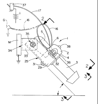
Fig. 1 is a schematic side elevation view of a preferred form of
animal warning alarm device in accordance with this invention shown
angled downwardly in a forward direction relative to a vehicle at an angle
approximately 45° to the road surface;
Fig. 2 is a top plan view of the device of Fig. 1 as seen from the
plane of line 2-2 thereof;
Fig. 3 is a front elevation view of the device of Fig. 1 as seen from
the plane of the line 3-3 thereof; and
Fig. 4 is a fragmentary longitudinal section through the device of Fig.
2 taken generally along the plane of the line 4-4 thereof.
-3-
CA 02317767 2000-09-06
DETAILED DESCRIPTION OF THE PREFERRED EMBODIMENT
Referring now in detail to the several figures of the drawing, there is
shown a preferred form of animal warning alarm device 1 in accordance
with this invention including a housing 2 having a hollow tube 3 projecting
forwardly from the front wall 4 thereof and a cover 5 projecting rearwardly
from the back wall 6 thereof. The housing 2 and tube 3 are desirably
integrally molded as one piece out of a suitable plastic, whereas the cover 5
is desirably separately molded out of a suitable plastic to permit the sonic
generator to be mounted in the device before the cover is secured in place
as described hereafter.
As clearly shown in Fig. 4, within the housing 2 are a pair of coaxial
stepped bores 7 and 8. The forwardmost stepped bore 7 has a diameter
somewhat greater than the diameter of the through passage 9 in the tube 3
to provide a radial shoulder 10 therebetween that acts as a stop for
locating a sonic generator 1 1 in the forwardmost stepped bore when
inserted from the rear and secured in place using a suitable adhesive or
potting compound or the like. Further, the rearmost stepped bore 8 has a
diameter somewhat greater than the diameter of the forwardmost stepped
bore 7 to provide a radial shoulder 12 therebetween that acts as a stop
limiting the extent of insertion of the open end 13 of the cover 5 into the
rearmost stepped bore.
Preferably, the outer wall 14 of the cover 5 is tapered toward the
open end 13 for ease of insertion of the open end into the rearmost
stepped bore 8 and is secured in place using a suitable adhesive/solvent
cement. In such outer wall 14 is a slot 15 (see Fig. 4) that extends from
the open end rearwardly of the rear wall 6 of the housing 2 for passage of
the power and ground leads 16, 17 from the sonic generator 1 1 exteriorly
of the housing.
The sonic generator 1 1 has a forwardly facing sound discharge
opening 18 in coaxial alignment with the passage 9 in the tube 3which is
preferably straight walled for channeling the sound wave passing through
-4-
CA 02317767 2000-09-06
the tube. Intermediate the passage 9 in the tube 3 and forwardmost
stepped bore 7 in the housing 2 is a chamber 19 having a diameter
somewhat smaller than the diameter of the forwardmost stepped bore 7
and somewhat greater than the diameter of the through passage 9 in the
tube for receipt of an acoustical foam layer 20 which covers the discharge
opening 18 in the sonic generator 1 1 to dampen the sound waves emitted
therefrom and keep any particles in the air from entering the sonic
generator through the passage 9 and possibly causing damage thereto.
Although the dimensions of the device may vary, in a preferred
embodiment of the present invention, the sound discharge opening 18 in
the sonic generator 1 1 has a diameter of approximately one-eighth inch,
and the passage 9 in tube 3 has a diameter of approximately three-eighths
inch and an axial length of approximately one and three-eighths inch. The
chamber 19 has a diameter of approximately seven-sixteenths inch and an
axial length of approximately five-eighths inch, and the forwardmost
stepped bore 7 has a diameter of approximately nine-sixteenth inch and an
axial length of approximately three-eighths inch, and the rearmost stepped
bore 8 has a diameter of approximately three-fourths inch and an axial
length of approximately one-fourth inch. Also, the sonic generator 1 1
preferably is designed to operate within a voltage range of eight to sixteen
volts direct current at an operating frequency of 4.8 + 0.5k Hz to produce
an ultrasonic wave of 18,000 to 21,000 Hertz at a sound pressure level of
120 dB (AS).
It has been found that such a device will produce a semi-directional
sonic wave that will carry in excess of 1,600 feet. Also, it has been found
that when such a device is angled downwardly toward the road surface in a
forward direction relative to the vehicle, the semi-directional sonic wave
produced by the device will be reflected off the road surface and produce a
virtual sonic echo effect that is very effective in alerting deer and most
other animals of an approaching vehicle with sufficient warning to
substantially reduce the risk of animal/vehicle collisions.
-5-
CA 02317767 2000-09-06
To achieve maximum effectiveness, the tube 3 should desirably be
angled downwardly in a forward direction at an angle of approximately
45°
to the road surface as schematically shown in Fig. 1. This causes the
sound emitted from the device to be reflected off the road surface and
produce different tones due to the different compositions of the road
surface and the constantly changing distance between the device and the
road surface due to the vibrations of the vehicle as the vehicle is driven
along the road surface.
To facilitate mounting of the device base 1 in the desired angular
orientation on a vehicle, one end of an L-shaped base bracket 25 may be
attached to a flange 26 on one side of the housing 2 by engaging one leg
27 of the base bracket with a flat bottom wall 28 on the flange and the
other leg 29 with a flat side wall 30 of the flange extending at a right angle
to the bottom wall, and inserting a bolt 31 upwardly through aligned holes
in the bottom leg and flange and threading a nut 32 onto the upper end of
the bolt protruding through the flange as schematically shown in Figs. 1
through 3. The other end of the base bracket 25 extends rearwardly of the
housing 2 for pivotal attachment of one leg 33 of an L-shaped mounting
bracket 34 to the side leg 29 of the base bracket using a suitable fastener
such as a nut and bolt and star washer assembly 35. The other leg 36 of
the mounting bracket 34 extends at a right angle to the first leg rearwardly
of the cover 5, and may have two or more mounting holes therein /not
shown) for attaching the mounting bracket at a suitable location on the
vehicle. For example, the mounting bracket may be attached behind the
grill or on the chassis of the vehicle or other suitable location where the
device 1 can be oriented with the tube facing forward in the normal
direction of movement of the vehicle but angled downwardly, preferably at
an angle of approximately 45° to the road surface, without any
obstructions in front of the tube opening.
The holes in the mounting bracket 34 may be located over existing
holes in the vehicle, or holes may be drilled in the vehicle in line with the
-6-
CA 02317767 2000-09-06
holes in the mounting bracket to permit the mounting bracket to be secured
in place using suitable screws, lug washers and nuts or self-tapping metal
screws or other suitable fasteners as desired. Once installed, the device 1
can easily be adjusted to achieve the desired angular orientation relative to
the road surface by loosening the nut and bolt connection 35 between the
mounting bracket 34 and base bracket 25 and pivoting the device to the
desired angular orientation and retightening the nut. Preferably the device
is mounted so that it is approximately six inches to a foot off the road
surface but could be as much as three feet off the road surface if desired.
When both the mounting and base brackets 34 and 25 are made of
metal and the mounting bracket 34 is mounted on a metal surface M of the
vehicle which is grounded as schematically shown in Fig. 1, the sonic
generator 1 1 can be grounded simply by attaching the ground wire 16 to a
terminal 36 formed by the upper end of the metal fastener 31 used to
fasten the base bracket 25 to the housing. If the vehicle surface on which
the device is mounted is not a vehicle ground, the ground wire 16 can be
removed from the terminal 36 and attached to any suitable grounded
surface G on the vehicle as depicted in phantom lines in Fig. 1.
The power lead 17 for the sonic generator 1 1 may be connected for
example to a dash mounted control switch 37, also schematically shown in
Fig. 1. Power to the control switch 37 may be provided by connecting the
control switch to any fused circuit, such as the radio or parking lights of
the vehicle, and may be made at the fuse block or under the dash as
desired.
When installed, the device may be used at any time. However, since
the high frequency sound wave that is generated by the device may be
irritating to some people especially in cities and congested areas, the
operator may only wish to use the device when driving in high risk areas
and on open roads. If desired, an indicator light 38 such as a light emitting
diode (LED) may be connected in parallel to the sonic generator circuit to
alert the user when the device is operating.
_7_
CA 02317767 2000-09-06
Although the invention has been shown and described with respect
to a certain preferred embodiment, it is obvious that equivalent alterations
and modifications will occur to others skilled in the art upon the reading and
understanding of the specification. The present invention includes all such
equivalent alterations and modifications, and is limited only by the scope of
the claims.
_g_