Note : Les descriptions sont présentées dans la langue officielle dans laquelle elles ont été soumises.
CA 02323602 2000-10-13
MULTIPURPOSE TOOL
FIELD OF THE INVENTION
The present invention relates to a multipurpose tool and more particularly,
relates to a multipurpose ironworker's tool.
BACKGROUND OF THE INVENTION
In construction, a variety of measuring and indicating devices are used to
ensure the correct placement and attachment of the various structural
components of a
building such as the foundation, walls, floors, roofs, etc. Typically, it is
important to
ascertain if structures are level in a horizontal plane and plumb in a
vertical line in
relation to the horizontal plane. Also, a variety of angles, including non-
square
angles, must be accurately measured and marked. Multiple calculations are
required
from the data supplied by these tools so that structures are placed correctly
within a
given foundation and the required accurate placement of structural components.
As
such, a plurality of tools is usually employed which include various types of
levels,
which can include line levels, water levels, plumb bobs, framing squares,
bevel
gauges, compasses, etc.
Obviously, while these tools have received wide acceptance within the building
trades, they do not address the time saving conveniences obtained with the
tool of the
present invention. The tool of the present invention combines many devices
into a
single tool and provides for extremely accurate and convenient marking of
structural
components and particularly, provides a tool useful in the ironworker's trade.
The present invention provides a tool which may be used as a level, both in
the
-1-
CA 02323602 2000-10-13
horizontal and vertical planes, and can also be used for marking various
angles, and
also incorporates a compass.
SUMMARY OF THE INVENTION
It is an object of the present invention to provide a multipurpose tool which
combines many functions in one and which may be utilized in many different
trades.
According to one aspect of the present invention, there is provided a
multipurpose tool comprising an elongated body portion, the body portion
having a
first and second end walls, and first and second pairs of opposed side walls
extending
between the first and second end walls, at least one of the end walls and one
of the
side walls being mutually perpendicular to each other, a plurality of level
indicating
means recessed in the body portion, the level indicating means being designed
to
indicate a vertical level, a horizontal level and a 45 angle thereto, at
least one magnet
recessed in the body portion, and a recess formed in one end of the body
portion, the
recess extending between the first pair of opposed side walls, a protractor
arm having
a longitudinally extending slot therein mounted in the recess.
In greater detail, the multipurpose tool of the present invention is designed
to
combine the features of a number of different individual tools. In particular,
in a
preferred embodiment, the multipurpose tool can function as a bevel square, a
combination square, a marking gauge, a torpedo level, a ruler, a compass, etc.
It may
find use both for the average handyman and also for commercial and industrial
use.
Thus, it can be used by woodworkers, metal workers, millwrights, etc.
As aforementioned, the multipurpose tool has a main body portion which may
-2-
CA 02323602 2000-10-13
be formed of any suitable material such as a wood or plastic material. In a
preferred
embodiment, the body portion is formed of a molded plastic material.
Preferably, although not essential, the body portion has a generally
rectangular
configuration with four sides and two ends. In this respect, in a preferred
embodiment, not all of the side walls are necessarily planer - there are
various
recesses and notches formed therein for purposes which will become clear from
the
description of the preferred embodiment. It suffices to say that there should
be at
least one end wall and one side wall each lying in a single plane such that
the various
level indicating devices may be used.
As aforementioned, there are various level indicating devices and preferably,
these are of the bubble tube variety wherein the bubble of a gas must be
aligned
between two lines to indicate a horizontal, perpendicular or 45 angle. In one
embodiment, there may be provided lighting means associated with each of the
level
indicating devices - these would be small lights adjacent thereto having a
battery
powered light which may be activated by touch.
The device includes a protractor arm which is retractable within the body of
the
multipurpose tool and which is preferably rotatable through 270 . In order to
precisely align the protractor arm at 270 from its recessed position, there
is preferably
provided a stop member. Also, in order to retain the protractor arm in any
desired
position, there may be provided locking means for doing so. Also, the
protractor arm
is preferably slidable within its mount such that its length may be adjusted.
As will be seen from the description of the preferred embodiments, there are
-3-
CA 02323602 2000-10-13
provided various notches and recesses which provide convenient places to hold
the
marking tools during the use of the device.
BRIEF DESCRIPTION OF THE DRAWINGS
Having thus generally described the invention, reference will be made to the
accompanying drawings, in which:
Figure 1 is a perspective view of one embodiment of a multipurpose tool
according to the present invention;
Figure 2 is a side elevational view thereof;
Figure 3 is a top plan view thereof;
Figure 4 is a bottom plan view thereof;
Figure 5 is a side view illustrating operation of the protractor arm; and
Figure 6 is a side view illustrating use of the multipurpose tool as a
compass.
DESCRIPTION OF THE PREFERRED EMBODIMENTS
Referring to the drawings in greater detail and by reference characters
thereto,
there is illustrated a multipurpose tool which is generally designated by
reference
numeral 10.
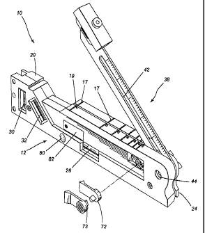
Multipurpose tool 10 includes a body portion 12 which, in general terms, has a
first pair of opposed side walls 14 and 16, and a second pair of opposed side
walls 18
and 20. First and second end walls 22 and 24 respectively are substantially
perpendicular to side walls 14, 16, 18 and 20 such that the overall
configuration is
rectangular.
Provided on side wall 18 are a plurality of indicia 26 for purposes of
-4-
CA 02323602 2007-08-03
measurement such as is commonly used by linear measuring devices.
Multipurpose tool 10 also includes a plurality of bubble tube level members
and
to this end, there is shown a horizontal bubble tube 28, a vertical bubble
tube 30, and
bubble tube 32 for a 45 angle. It will be understood that the terms
horizontal and
vertical are relative and depend on the orientation of the device.
In the illustrated embodiment, a pair of magnets 34 are provided recessed
within
side wall 18, magnets 34 being particularly useful when the device is employed
on steel
beams. Also, a groove 48 is formed in side wall 14 to enable mounting on a
cylindrical
member such as a pipe.
There is also provided a protractor arm which is generally designated by
reference numeral 38 and which protractor arm carries indicia 40 thereon again
for
purposes of measurement. A longitudinally extending slot 42 is used for
mounting
protractor arm 38 and to this end, there is provided a mounting member 44
having a
wing nut 46 such that protractor arm 38 can be tightened in any desired
position. As
shown in Figure 5, protractor arm 38 may extend through 270 . It will also be
noted that
at its distal end, protractor arm 3 8 has a bevelled shape while at its
proximal end, it has
an arcuate configuration.
End wall 24, as may best be seen in Figure 4, has at its outer periphery a
recess or
notch 50 formed therein. Similarly, end wall 22 has a recess 54 formed
thereat. Recess
54 is useful as a heel portion when the multipurpose tool is placed on an H-
beam as is
commonly done by ironworkers before tracing a marking line.
Located at end wall 22 is a recess generally designated by reference numeral
68
-5-
CA 02323602 2000-10-13
(Figure 4) and which is designed to receive a moveable pin or compass point 60
which is moveable through a snap and pivot member 62 (shown in dotted lines).
Within side wall 20, there is provided a recess generally designated by
reference numeral 64 to permit ready access to protractor arm 38. It will also
be noted
that the wall is formed such that there is a notch generally designated by
reference
numeral 66 which may be utilized as a place to receive the end of a tape of a
tape
measure device in order to measure the distance with respect to the opening of
the
protractor arm such that the same angle can be transferred.
In order to ensure the perpendicularity of protractor arm 3 8 with respect to
side
wall 18, there is provided a stop member 70. Similarly, there are provided
moveable
stop members 72 and 73 placed such that protractor arm 38 is temporarily
stopped at
an angle of 45 and 30 respectively. It will also be seen that side wall 20
includes
notches 17 with indicia 19 to indicate the angle that protractor arm 38 forms
with
respect to side wall 20.
In the preferred embodiment, and as shown in the drawings, there is provided a
light 74 mounted adjacent horizontal bubble tube 28 such that easier visual
access
may be gained thereto. Similarly, there is provided a light 76 adjacent
vertical bubble
tube 30 and a light 78 adjacent 45 bubble tube 32. Lights 74, 76 and 78 are
LED's
which are operated by switch 80. A suitable battery is mounted within door 82.
Protractor arm 38 has, at its distal end, an angled end 84 and in which there
is
provided a notch 86. Notch 86 is designed to be used with a marking device
such as a
pencil such that it will not slip when marking an object. Protractor arm 38
also has a
-6-
CA 02323602 2000-10-13
proximal end 88 which is of an arcuate configuration and has a notch 90
therein.
As may be seen in Figures 2 and 6, end wall 24 also has an arcuate recess 94.
This facilitates the holding of the device in use and is designed to receive a
finger of
the user.
A holding device generally designated by reference numera198 is designed to
be attached to the distal end of protractor arm 38 by means of a retaining
member 104.
In turn, holding device 98 is designed to receive a marking device 102 by
means of
screw 100.
It will be understood that the above described embodiments are for purposes of
illustration only and that changes or modifications may be made thereto
without
departing from the spirit and scope of the invention.
-7-