Note : Les descriptions sont présentées dans la langue officielle dans laquelle elles ont été soumises.
CA 02328166 2000-10-06
WO 00/55873 PCT/US00/06793
TITLE: Inductor,Coil Structure And Method For Making Sarne
~ACKGR UND OF THE INVENTION
The present invention relates to an inductor coil structure and method for
making
same. The coil structure of the present invention is preferably for use in a
high current low
profile inductor commonly referred to by the designation IHLP. However, the
particular
coil structure may be used in other types of inductors.
Inductor coils have in the prior art been constructed from various shapes of
materials formed into various helical shapes. However, there is a need for an
improved
to inductor coil structure which is simple to manufacture and which provides
an efficient and
reliable inductance coil.
Therefore, a primary object of the present invention is the provision of an
improved
inductor coil structure and method for making same.
A further object of the present invention is the provision of an inductor coil
15 structure which can be used in a high current low profile inductor having
no air spaces in
the inductor, and which includes a magnetic material completely surrounding
the coil.
A further object of the present invention is the provision of an inductor coil
structure which includes a closed magnetic system which has self shielding
capability.
A further object of the present invention is the provision of an inductor coil
2o structure which maximizes the utilization of space needed for a given
inductance
performance so that the inductor can be of a minimum size.
A further object of the present invention is the provision of an improved
inductor
coil structure which is smaller, less expensive to manufacture, and is capable
of accepting
more current without saturation than previous inductor coil structures,
25 A further object of the present invention is the provision of an inductor
coil
structure which lowers the series resistance of the inductor.
SUMMARY OF THE INVENTION
The foregoing objects may be achieved by a high current low profile inductor
3o comprising a conductor coil having first and second coil ends. A magnetic
material
surrounds the conductor coil to form an inductor body. The inductor coil
comprises a
CA 02328166 2000-10-06
WO 00/55873 PCT/US00/06793
plurality of coil turns extending around a longitudinal coil axis in an
approximately helical
path which progresses axially along the coil axis. The coil turns are fornned
from a flat
plate having first and second opposite flat surfaces, at least a portion of
each of the flat
surfaces of the coil turns facing in a axial direction with respect to the
coil axis.
The method for making the inductor includes taking an elongated plate
conductor
having a first end, a second end, opposite side edges, opposite flat surfaces,
and a
longitudinal plate axis. A plurality of slots are cut in each of the opposite
side edges of the
plate conductor so as to form the plate conductor into a plurality of cross
segments
extending transversely with respect to the plate axis and a plurality of
connecting segments
1o extending approximately axially with respect to the plate axis. The
connecting segments
connect the cross segments together into a continuous conductor which extends
in a sine
shaped path. As used herein the term "sine shaped" refers to any shape which
generally
conforms to a sine curve, but which is not limited to a continuous curve and
may include
apexes, squared off corners or other various shapes.
After cutting the slots in the opposite side edges of the plate conductor the
connecting segments are bent along one or more bend axes extending
transversely with
respect to the plate axis so as to form the plate conductor into a plurality
of accordion folds,
each of which comprise one of the cross segments and a portion of one of the
connecting
segments. In the resulting structure, the cross segments and the connecting
segments form
2o a continuous conductor coil of approximate helical shape having first and
second opposite
ends.
BRIEF DESCRIPTION OF THE FIGURES OF THE DRAWINGS
Figure 1 is a perspective view of the inductor constructed in accordance with
the
present invention and mounted upon a circuit board.
Figure 2 is a pictorial view of the coil of the inductor before the molding
process.
Figure 3 is a pictorial view of the inductor of the present invention after
the
molding process is complete, but before the leads have been formed.
Figure 4 is an end elevational view taken along line 4-4 of Figure 2.
3o Figure 5 is an elevational view taken along lines 5-5 of Figure 4.
CA 02328166 2000-10-06
WO 00/55873 PCTIUS00106793
Figure 6 is a perspective view of an elongated conductor blank from which the
inductor coil is formed.
Figure 7 shows the blank of Figure 6 after the formation of slots extending
inwardly from the opposite edges thereof.
Figure 8 is a view similar to Figure 7, showing the first folding step in the
formation of the inductor coil of the present invention.
Figure 9 is a side elevational view showing the same folding step shown in
Figure 8.
Figure I O is a view similar to 8 and showing a second folding step in the
process
to for making the inductor coil of the present invention.
Figure 11 is an inverted pictorial view of the inductor after it has been
pressed, but
before the leads have been formed.
Figure 12 is a view similar to figure 11 showing the inductor after partial
forming
of the leads.
Figure 13 is a view similar to Figures 1 l and 12 showing the final forming of
the
leads.
SAILED DESCRIPTION OF THE PREFERRI~D EMBODIMENT
Referring to the drawings the numeral 10 generally designates an inductor of
the
2o present invention mounted upon a circuit board 12. Inductor 10 includes an
inductor body
14 having a first lead 16 and a second lead 18 extending therefrom and being
folded over
the opposite ends of body 14. Leads 16, 18 are soldered or otherwise
electrically
connected on the circuit board 12.
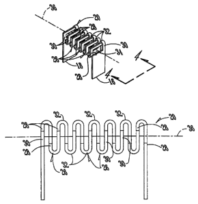
Referring to Figure 2, the inductor coil of the present invention is generally
designated by the numeral 20. Leads 16, 18 form the ends of coil 22. Between
leads 16,
18 are a plurality of L-shaped coil segments 26 each comprising a horizontal
leg 28 and a
vertical leg 30. Vertical leg 30 terminates at a connecting segment 32 which
is folded over
at approximately 180° so as to create an accordion like configuration
fox inductor coil 20.
The L-shaped coil segments are connected together to form a helical coil
having an open
coil center 34 extending along a longitudinal coil axis 36.
3
CA 02328166 2000-10-06
WO 00155873 PCT/US00/06793
Figures 6-10 show the process for making the coil 20. Initially as shown in
Figure
6 a blank flat conductor plate 50 formed of copper or other electrically
conductive material
includes: first and second ends 52, 54; a pair of opposite flat surfaces 56;
and a pair of
opposite side edges 58, 60.
Figure 7 shows the first step in forming the coil 20. In this step a plurality
of slots
62, 64 are cut in the opposite edges 58, 60 respectively of the blank flat
plate 50. Various
cutting methods may be used such as stamping or actual cutting by laser ar
other cutting
tools known in the art.
Upon completion of the cutting operation, the blank 50 is transformed into an
1o elongated sine shaped body formed from a plurality of cross segments 66
extending
transversely to the longitudinal axis of plate 50 and a plurality of
connecting segments 67
extending axially with respect to the longitudinal axis of plate 50. The
segments 66, 67
form a continuous sine shaped conf guration as shown in Figure 7.
Figure 8 shows the next step in forming the coil 20. The end 52 is folded over
at an
15 angle of 180° to form the 180° angle bend 63 in the first
connecting segment 67. Figure 10
shows a second bend 65 which is in the next connecting segment 67. Bends 63,
65 are in
opposite directions, and are repeated until an accordion like structure is
provided similar to
that shown in Figure 5.
In Figure 5 the coil 20 includes opposite ends 16, 18 which are formed from
the
20 opposite ends 52, 54 of blank 50. The cross segments 66 of blank 50 form
the first
horizontal legs 28 of coil 20, and the connecting segments 67 of blank 50 form
the second
vertical legs 30 and the connecting segments 32 of coil 20.
An example of a preferred material for coil 20 is a copper flat plate made
from
OFHC copper 102, 99.95% pure.
25 The magnetic molding material of body 14 is comprised of a powdered iron, a
filler, a resin, and a lubricant. The preferred powdered material is
manufactured by BASF
Corporation, 100 Cherryhill Road, Parsippany, New Jersey under the trade
designation
Carbonyl Iron, Grade SQ. This SQ material is insulated with 0.875% mass
fraction with
75% H3P04.
4
CA 02328166 2000-10-06
WO 00/55873 PCT/US00/06793
An epoxy resin is also added to the mixture, and the preferred resin for this
purpose
is manufactured by Morton International, Post Office Box 15240, Reading,
Pennsylvania
under the trade designation Corvel Black, Number 10-7086.
In addition a lubricant is added to the mixture. The lubricant is a zinc
stearate
manufactured by Witco Corporation, Box 45296, Huston Texas under the product
designation Lubrazinc W.
Vaxious combinations of the above ingredients may be mixed together, but the
preferred mixture is as follows:
1,000 grams of the powdered iron.
io 3.3% by weight of the resin.
0.3% by weight of the lubricant.
The above materials (other than the lubricant) are mixed together and then
acetone is added
to wet the material to a mud-like consistency. The material is then permitted
to dry and is
screened to a particle size of -50 mesh. 'The lubricant is then added to
complete the material
82. The material 82 is then ready for pressure molding.
The next step in the process involves compressing the material completely
around
the coil 20 so that it has a density produced by exposure to pressure of from
15 to 25 tons
per square inch. This causes the powdered material 82 to be compressed and
molded
tightly completely around the coil so as to form the inductor body 14 shown in
Figure 1
and in Figures I 1-13.
At this stage of the production the molded assembly is in the form which is
shown
in Figure 11. After baking, the leads 16, 18 are formed or bent as shown in
Figures I2 and
13. The molded assemblies are then baked at 325°F for one hour and
forty-five minutes to
set the resin.
When compared to other inductive components the IHLP inductor of the present
invention has several unique attributes. The conductive coil, lead frame,
magnetic core
material, and protective enclosure are molded as a single integral low profile
unitized body
that has termination leads suitable for surface mounting. The construction
allows for
maximum utilization of available space for magnetic performance and is
magnetically self
shielding.
5
CA 02328166 2000-10-06
WO 00/55873 PCTIUS00/06793
The unitary construction eliminates the need for two core halves as was the
case
with prior art E cores or other core shapes, and also eliminates the
associated assembly
labor.
The unique conductor winding of the present invention allows for high current
operation and also optimizes magnetic parameters within the inductor's
footprint.
The manufacturing process of the present invention provides a low cost, high
performance package without the dependence on expensive, tight tolerance core
materials
and special winding techniques.
The magnetic core material has high resistivity (exceeding 3 mega ohms) that
1o enables the inductor as it is manufactured to perform without a conductive
path between
the surface mount leads. The magnetic material also allows efficient operation
up to 1
MHz. The inductor package performance yields a low DC resistance to inductance
ratio of
two milliOhms per microHenry. A ratio of S or below is considered very good.
The unique configuration of the coil 20 reduces its cost of manufacture. Coil
20
15 may be used in various inductor configurations other than IHLP inductors.
In the drawings and specification there has been set forth a preferred
embodiment
of the invention, and although specific terms are employed these are used in a
generic and
descriptive sense only and not for purposes of limitation. Changes in the form
and the
proportion of parts as well as in the substitution of equivalents are
contemplated as
2o circumstances may suggest or render expedient without departing from the
spirit or scope
of the invention as further defined in the following claims.
6