Sélection de la langue

Search

Sommaire du brevet 2330264 

Énoncé de désistement de responsabilité concernant l'information provenant de tiers

Une partie des informations de ce site Web a été fournie par des sources externes. Le gouvernement du Canada n'assume aucune responsabilité concernant la précision, l'actualité ou la fiabilité des informations fournies par les sources externes. Les utilisateurs qui désirent employer cette information devraient consulter directement la source des informations. Le contenu fourni par les sources externes n'est pas assujetti aux exigences sur les langues officielles, la protection des renseignements personnels et l'accessibilité.

Disponibilité de l'Abrégé et des Revendications

L'apparition de différences dans le texte et l'image des Revendications et de l'Abrégé dépend du moment auquel le document est publié. Les textes des Revendications et de l'Abrégé sont affichés :

  • lorsque la demande peut être examinée par le public;
  • lorsque le brevet est émis (délivrance).
(12) Demande de brevet: (11) CA 2330264
(54) Titre français: RACCORD ANGULAIRE REGLABLE ENTRE UNE TETE DE CLE ET UN CORPS
(54) Titre anglais: ANGLE ADJUSTABLE JOINT BETWEEN A WRENCH HEAD AND A SHANK
Statut: Morte
Données bibliographiques
(51) Classification internationale des brevets (CIB):
  • B25B 23/16 (2006.01)
  • B25B 23/00 (2006.01)
  • B25G 1/06 (2006.01)
(72) Inventeurs :
  • LEE, JACK (Taïwan, Province de Chine)
(73) Titulaires :
  • LEE, JACK (Taïwan, Province de Chine)
(71) Demandeurs :
  • LEE, JACK (Taïwan, Province de Chine)
(74) Agent: RICHES, MCKENZIE & HERBERT LLP
(74) Co-agent:
(45) Délivré:
(22) Date de dépôt: 2001-01-05
(41) Mise à la disponibilité du public: 2002-07-05
Requête d'examen: 2001-01-05
Licence disponible: S.O.
(25) Langue des documents déposés: Anglais

Traité de coopération en matière de brevets (PCT): Non

(30) Données de priorité de la demande: S.O.

Abrégés

Abrégé anglais


A wrench tool includes a shank (20) having two lugs (21) and a recess
(22) is defined in the end of the shank and communicates with a receiving
space
between the two lugs. An operation member (30) is rotatably received in the
recess and has first teeth (32). A head (40) has a connection port (43) which
is
pivotally connected between the two lugs and the connection port has second
teeth (430) which are engaged with the first teeth of the operation member.

Revendications

Note : Les revendications sont présentées dans la langue officielle dans laquelle elles ont été soumises.


6

The embodiment of the invention in which an exclusive property or privilege is
claimed are defined as follows:

1. A wrench tool comprising:
a shank having two lugs extending from an end thereof and a receiving
space defined between said two lugs, a recess defined in said end of said
shank
and communicating with said receiving space, an operation member rotatably
received in said recess and having first teeth defined in an outer periphery
thereof, and
a head having a connection port which is pivotally connected between
said two lugs by a pin and said connection port having second teeth which are
engaged with said first teeth of said operation member.

2. The tool as claimed in claim 1, wherein said operation member has a
passage defined longitudinally therethrough and a threaded hole is defined in
an
inner periphery defining said recess, a bolt extending through said passage of
said bolt 33 and engaged with said threaded hole.

3. The tool as claimed in claim 1, wherein said operation member has a
section located above a surface of said end of said shank.


Description

Note : Les descriptions sont présentées dans la langue officielle dans laquelle elles ont été soumises.

CA 02330264 2001-O1-05
2
ANGLE ADJUSTABLE JOINT BETWEEN A WRENCH HEAD AND A
SHANK
FIELD OF THE INVENTION
The present invention relates to a wrench whose head has teeth
engaged with a threaded operation member in the shank so that the head can be
angle adjustable relative to the shank by rotating the operation member.
BACKGROUND OF THE INVENTION
A conventional wrench is shown in Fig. 5 and generally includes a
head 11 having a slot defined between lugs and an engaging member 10 is
pivotally connected between the two lugs by a pin 100. A recess 14 is defined
in
an inner periphery defining the recess 14 so as to receive a spring 13 and a
ball
12 therein. The ball 12 is pushed by the spring 13 to engage with an end of
the
engaging member 10. The engaging member 10 i.s then pivotable about the pin
100 and set at a angle by the engagement of the ball 12 and the end of the
engaging member 10. Although the engaging member 10 can be set at different
positions to meet the needs of the users, the engagement of the ball 12 and
the
end of the engaging member 10 is not secure enough so that the engaging
member 10 is easily to slip when a force is applied to the engaging member 10.
The users have to re-adjust the engaging member 10 again.
The present invention intends to provide an angle adjustable structure
for a wrench head by using a threaded rod to engage with a toothed end of the
engaging member.

CA 02330264 2001-O1-05
3
SUMMARY OF THE INVENTION
In accordance with one aspect of the present invention, there is
provided a wrench tool and comprising a shank with two lugs extending from an
end thereof and a recess defined in the end of the shank and communicating
with
a receiving space defined bf;tween the two lugs. An operation member is
rotatably received in the recess and has first teeth. A head has a connection
port
which is pivotally connected between the two lugs and the connection port has
second teeth which are engaged with the first teeth of the operation member.
The
head is set at an angle relative to the shank by rotating the operation
member.
The primary object of the present invention is to provide a wrench
whose head can be pivoted and securely set relative to the shank.
These and further objects, features and advantages of the present
invention will become more o~>vious from the following description when taken
in connection with the accompanying drawings which show, for purposes of
illustration only, several embodiments in accordance with the present
invention.
BRIEF DESCRIPTION OF THE DRAWINGS
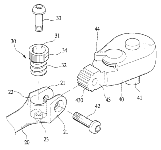
Fig. 1 is an exploded view to show a wrench tool of the present
invention;
Fig. 2 is a perspective view to show the wrench tool of the present
invention;
Fig. 3 is a cross sectional view to show that the operation member is
engaged with the connection port of the head of the wrench tool of the present
invention;

CA 02330264 2001-O1-05
~l
Fig. 4 is a cross sectional view to show that the operation member is
engaged with the connection port of the head when the shank of the wrench tool
is rotated an angle, and
Fig. 5 is a cross sectional view to show a conventional wrench tool.
DETAILED DESCRIPTION OF THE PREFERRED EMBODIMENT
Referring to Figs. 1 to 3, the wrench tool of the present invention
comprises a shank 20 having two lugs 21 extending from an end thereof and a
receiving space is defined between the two lugs 21. A recess 22 is defined in
the
end of the shank 20 and communicates with the receiving space. An operation
member 30 is rotatably received in the recess 22 and has first teeth 32
defined in
an outer periphery thereof. The operation member 30 has a passage 31 defined
longitudinally therethrough and a threaded hole 23 is defined in an inner
periphery defining the recess 22. A bolt 33 extends through the passage 31 of
the bolt 33 and is engaged with the threaded hole 23. The operation member 30
has a section 34 located above a surface of the end of the shank 20 and the
section 34 has a knurl surface fbr convenience of rotation.
A head 40 has a connection port 43 which is pivotally connected
between the two lugs 21 by a pin 42 and the connection port 43 has second
teeth
430 which are engaged with the first teeth 32 of the operation member 30. The
head 40 has an engaging rod 41 extending therefrom and a ratchet mechanism
(not shown) in the head 40 is control by a shifting lever 44 on the head 40.
Referring to Fig. 4, an angle between the shank 20 and the head 40 can
be changed or adjusted by rotating the operation member 30, the rotation of
the

CA 02330264 2001-O1-05
operation member 30 rotates t:he connection port 43. The engagement between
the first teeth 32 and the second teeth 430 is more secure compared with the
ball
12 and the engaging member 10 as disclosed in Fig. S so that the head 40 will
not slip during operation of the: wrench tool.
5 While we have shown and described an embodiment in accordance
with the present invention, it should be clear to those skilled in the art
that
further embodiments may be made without departing from the scope and spirit
of the present invention.

Dessin représentatif
Une figure unique qui représente un dessin illustrant l'invention.
États administratifs

Pour une meilleure compréhension de l'état de la demande ou brevet qui figure sur cette page, la rubrique Mise en garde , et les descriptions de Brevet , États administratifs , Taxes périodiques et Historique des paiements devraient être consultées.

États administratifs

Titre Date
Date de délivrance prévu Non disponible
(22) Dépôt 2001-01-05
Requête d'examen 2001-01-05
(41) Mise à la disponibilité du public 2002-07-05
Demande morte 2004-01-05

Historique d'abandonnement

Date d'abandonnement Raison Reinstatement Date
2003-01-06 Taxe périodique sur la demande impayée

Historique des paiements

Type de taxes Anniversaire Échéance Montant payé Date payée
Le dépôt d'une demande de brevet 150,00 $ 2001-01-05
Requête d'examen 200,00 $ 2001-01-05
Titulaires au dossier

Les titulaires actuels et antérieures au dossier sont affichés en ordre alphabétique.

Titulaires actuels au dossier
LEE, JACK
Titulaires antérieures au dossier
S.O.
Les propriétaires antérieurs qui ne figurent pas dans la liste des « Propriétaires au dossier » apparaîtront dans d'autres documents au dossier.
Documents

Pour visionner les fichiers sélectionnés, entrer le code reCAPTCHA :


Pour visualiser une image, cliquer sur un lien dans la colonne description du document. Pour télécharger l'image (les images), cliquer l'une ou plusieurs cases à cocher dans la première colonne et ensuite cliquer sur le bouton "Télécharger sélection en format PDF (archive Zip)" ou le bouton "Télécharger sélection (en un fichier PDF fusionné)".

Liste des documents de brevet publiés et non publiés sur la BDBC .

Si vous avez des difficultés à accéder au contenu, veuillez communiquer avec le Centre de services à la clientèle au 1-866-997-1936, ou envoyer un courriel au Centre de service à la clientèle de l'OPIC.


Description du
Document 
Date
(yyyy-mm-dd) 
Nombre de pages   Taille de l'image (Ko) 
Dessins représentatifs 2002-06-10 1 11
Abrégé 2001-01-05 1 18
Description 2001-01-05 4 142
Revendications 2001-01-05 1 30
Dessins 2001-01-05 5 57
Page couverture 2002-07-05 1 36
Cession 2001-01-05 3 86
Correspondance 2005-03-02 1 32