Sélection de la langue

Search

Sommaire du brevet 2334102 

Énoncé de désistement de responsabilité concernant l'information provenant de tiers

Une partie des informations de ce site Web a été fournie par des sources externes. Le gouvernement du Canada n'assume aucune responsabilité concernant la précision, l'actualité ou la fiabilité des informations fournies par les sources externes. Les utilisateurs qui désirent employer cette information devraient consulter directement la source des informations. Le contenu fourni par les sources externes n'est pas assujetti aux exigences sur les langues officielles, la protection des renseignements personnels et l'accessibilité.

Disponibilité de l'Abrégé et des Revendications

L'apparition de différences dans le texte et l'image des Revendications et de l'Abrégé dépend du moment auquel le document est publié. Les textes des Revendications et de l'Abrégé sont affichés :

  • lorsque la demande peut être examinée par le public;
  • lorsque le brevet est émis (délivrance).
(12) Brevet: (11) CA 2334102
(54) Titre français: DISPOSITIF FORMANT UNE SEPARATION ENTRE ETAGES
(54) Titre anglais: DEVICE FORMING A PARTITION BETWEEN STOREYS
Statut: Réputé périmé
Données bibliographiques
(51) Classification internationale des brevets (CIB):
  • E04B 5/14 (2006.01)
  • E01C 11/26 (2006.01)
  • E01C 13/02 (2006.01)
  • E04B 5/48 (2006.01)
  • F24D 5/10 (2006.01)
(72) Inventeurs :
  • VOLSTAD, OVE CHARLES (Norvège)
(73) Titulaires :
  • VOLSTAD ENERGY AS (Norvège)
(71) Demandeurs :
  • VOLSTAD ENERGY AS (Norvège)
(74) Agent: NORTON ROSE FULBRIGHT CANADA LLP/S.E.N.C.R.L., S.R.L.
(74) Co-agent:
(45) Délivré: 2007-08-21
(86) Date de dépôt PCT: 1999-05-20
(87) Mise à la disponibilité du public: 1999-12-09
Requête d'examen: 2004-05-14
Licence disponible: S.O.
(25) Langue des documents déposés: Anglais

Traité de coopération en matière de brevets (PCT): Oui
(86) Numéro de la demande PCT: PCT/NO1999/000162
(87) Numéro de publication internationale PCT: WO1999/063179
(85) Entrée nationale: 2000-12-01

(30) Données de priorité de la demande:
Numéro de la demande Pays / territoire Date
19982520 Norvège 1998-06-02

Abrégés

Abrégé français

L'invention se rapporte à un dispositif constituant une pièce de construction (1), de préférence disposée entre des parties de support (10, 11, 12) d'une structure de bâtiment ou d'usine, et formant de préférence une séparation entre étages, du type plancher ou terrasse. Cette pièce de construction (1) est auto-portée, de préférence fabriquée dans un matériau léger, et comporte un système de canaux pour l'air, de sorte que ladite pièce de construction (1) peut assurer le chauffage et/ou le refroidissement des pièces de la structure de bâtiment ou d'usine, ou peut assurer la fonte de glace ou de neige se trouvant sur ladite pièce de construction. Celle-ci est constituée d'au moins trois couches interconnectées (2, 3, 4) de matériau ondulé. Ces couches (2, 3, 4) sont disposées de façon à former des angles les unes avec les autres, de telle sorte que les ondulations forment entre elles de préférence un angle droit, ce qui permet la constitution entre les ondulations de couches (2, 3, 4) d'un système de canaux dans la pièce de construction (1). Un certain nombre de trous (6) sont ménagés dans la couche intermédiaire (3). Ces trous (6) sont formés transversalement à un plan, et de préférence dans un plan, traversant la section intermédiaire des ondulations, de sorte que l'air à une température adaptée au chauffage et/ou au refroidissement, ou à la fonte, respectivement, peut être introduit dans le système de canaux et/ou extrait dudit système de manière contrôlée. On remplit avantageusement les ondulations de la couche supérieure (4) en y coulant un matériau léger supplémentaire ayant une bonne conductivité thermique, jusqu'à un niveau atteignant au moins la hauteur des crêtes des ondulations de la couche ondulée supérieure (4).


Abrégé anglais


The invention relates to a device by a constructional
part (1) preferably extending between supporting
parts (10, 11, 12) of a building or plant construction,
and preferably forming a partition between
storeys, such as a floor or deck. The constructional
part (1) is self-supported, preferably of light-weight
material and comprises a channel system for air, so
that the constructional part (1) may provide heating
and/or cooling of rooms in the building or plant construction,
or may thaw snow and ice lying on the construciontal
part, respectively. The constructional part
(1) is made up of at least three interconnected layers
(2, 3, 4) of corrugated sheet material. The layers (2, 3,
4) are arranged at angles in relation to each other, in
such a way that corrugations form a preferably right
angle between themselves, so that the corrugations of
the layers (2, 3, 4) form a channel system in the constructional
part (1). A number of holes (6) are made
in the intermediate layer (3). The holes (6) extend
transversely to and preferably in a plane through the
mid section of the corrugations, so that air at a temperature
suitable for heating and/or cooling, or thawing,
respectively, may be supplied and/or extracted in a
controlled manner in the channel system formed. The
corrugations of the upper layer (4) are advantageously
filled with an additional cast (5) of light-weight material
of good thermal conductivity to a level at least
at the height of the corrugation ridges of the upper
sheet layer (4).

Revendications

Note : Les revendications sont présentées dans la langue officielle dans laquelle elles ont été soumises.


7
CLAIMS:

1. Arrangements in constructural elements intended to be incorporated in a
building
or plant construction, in which said constructural element will be orientated
in a
substantially horizontal position, forming a partition between storeys, such
as a
floor or a deck, said constructural element being shaped and designed with a
channel system for flowing air, and comprising at least two parallel layers in
the
form of interconnected corrugated sheets, the corrugations of two layers
crossing
each other perpendicularly, wherein said constructural element additionally
comprises at least one further corrugated sheet constituting a third,
intermediate
layer between two external layers, one upper layer and one lower layer as
referred
to the horizontal position of use, said intermediate corrugated sheet being
shaped
with a plurality of through going lateral holes interconnecting air spaces
forming
air channel systems at either side of said intermediate sheet, defined by the
internal side faces of the corrugated sheets surrounding said third corrugated

sheet.

2. Arrangements as set forth in claim 1, wherein the lateral holes in the
intermediate
layer are positioned in the middle portion of the intermediate layer.

3. Arrangements as set forth in claim 1 or 2, wherein the troughs of the
corrugations
of the upper layer are filled with a castable, hardenable, light-weight
material
exhibiting good thermal conducting properties, to a level positioned at least
corresponding to the level of the wave crests of the corrugations.

4. Arrangements as set forth in claim 3, wherein the corrugation wall of the
upper
sheet to be filled with said castable material is provided with embossings.

5. Use of a multilayer-constructural element shaped and designed in accordance
with
claim 1 as floor or paving disposed substantially horizontally, covering a
free
span, wherein the multilayer-constructural element is shaped, designed and


8
dimensioned so as to be self-supporting, withstanding bending strains,
compressive and tensile tensions.

Description

Note : Les descriptions sont présentées dans la langue officielle dans laquelle elles ont été soumises.


CA 02334102 2000-12-01

WO 99/63179 PCT/NO99l00162
DEVICE FORMING A PARTITION BETWEEN STOREYS

s The invention relates to a device by a. constructional part
preferably extending between supporting parts of a building
or plant construction, and preferably forming a partition be-
tween storeys, such as a floor or deck.

In known building and plant constructions the storey-
separating constructional part is normally of concrete. The
constructional part usually extends between the supporting
parts of the building or plant construction, and is either
cemented in situ or is in the form of prefabricated elements.
Work on such constructional parts of concrete is resource de-
is manding in its own ways. The use of heavy material such as
concrete in the partition between storeys, entails that the
supporting parts must be increased in size. Besides, each
storey must be provided with additional height of at least 30
cm to provide room for channels for the air normally used for

heating and/or cooling rooms in the building or plant con-


CA 02334102 2000-12-01

2
WO 99/63179 PCT/N099/00162
struction. All these things are cost-increasing conditions of
known constructions.

Among persons skilled in the art, there is a certain scepti-
cism towards the use of material other than concrete in e.g.
storey-separating constructional parts. Said scepticism in-
volves, among other things, doubt as to carrying capacity,
durability, etc. Neither has there been any capability of
utilising the partition between storeys for carrying for ex-
ample air which is used for heating and cooling. The objec-
tions in this matter are that the carr;ying capacity will be
weakened, that the constructional part cannot be used for
heating and cooling in a suitable manner, etc.

Besides, it is well known that the wor:k of clearing snow and
ice results in great costs during construction, as well as
1s during the subsequent operation and maintenance of the build-
ing and the plant construction.

An object of the present invention is to avoid, to the great-
est possible degree, the above heavy, work-demanding and
cost-increasing constructional parts in concrete. Other ob-
jects are to reduce the storey height by the use of freely
suspended air channels being avoided. Likewise, it is desired
to provide a more efficient means of removing snow and ice
lying on the constructional part, for instance when it forms
part of the roof of the building or plant, and which means

may be used for thawing snow and ice while the building or
plant construction is under construction.

This has been realised by means of the present device by a
constructional part preferably extending between supporting
parts of a building or plant construction, and preferably


CA 02334102 2007-05-17

W099/63179 -3- PCT/N099/00162
forming a partition between storeys, such as a floor a
deck. The constructional part is self-supporting,
preferably of light-weight material and comprises a
channel system , so that the constructional part may be

utilised for heating and/or cooling of rooms in the
building or plant construction, or may thaw snow or ice
lying on the constructional part, respectively. The
constructional part is made up of at least three
interconnected layers of corrugated sheet material. The

layers are placed at angles in such a way that
corrugations form a preferably right angle between
themselves, so that the corrugations of the sheet layers
form a channel system. The channels are interconnected by
a number of holes having been made in the intermediate

layer. The holes extend transversely to and preferably in
one plane through the mid section of the layer, so that
air at a temperature adjusted for heating and/or cooling
and thawing, respectively, may be taken through the

formed channel system in a controlled manner.

Other advantageous features of the invention will appear
from the fallowing part of the specification and the
dependent claims.

There is therefore provided, in accordance with one
aspect of the present invention, arrangements in
constructural elements intended to be incorporated in a
building or plant construction, in wich said
constructural element will be orientated in a
substantially horizontal position, forming a partition

between storeys, such as a floor or a deck, said
DOCSMTL: 2391592\I


CA 02334102 2007-05-17
- 3a-

constructural element being shaped and designed with a
channel system for a flowing air, and comprising at least
two parallel layers in the form of interconnected
corrugated sheets, the corrugations of two layers

crossing each other perpendicularly, wherein said
constructural element additionally comprises at least one
further corrugated sheet constituting a third,
intermediate layer between two external layers, one upper
layer and one lower layer as referred to the horizontal

1o position of use, said intermediate corrugated sheet being
shaped with a plurality of through-going lateral holes
interconnecting air spaces forming air channel systems at
either side of said intermediate sheet, defined by the
internal side faces of the corrugated sheets surrounding

said third corrugated sheet.Referring to the set of
figures, preferable non-limiting embodiments of the
invention will be explained in further detail.

Fig. 1 shows schematically a view of the present
constructional part, drawn so that the configuration
shows;

Fig. 2 shows a schematic vertical section of for example
a detached house in which the constructional part is used
as a floor on the ground in the lowermost storey, and
possibly in the roof of the detached house; and


CA 02334102 2000-12-01

4
WO 99/63179 PCT/N099/00162
Fig. 3 shows a schematic vertical section through a building
of several storeys, in which the constructional part is used
as a partition which forms floor and ceiling of the building.
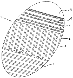
According to the invention, the present constructional part 1
should preferably form a storey-separating part such as a
floor or deck in a building or plant construction. The build-
ing or plant construction may be of different types, e.g. a
detached house, a multi-storey building, a road bridge etc.
The constructional part 1 which is self-supporting and of
light-weight material extends between supporting parts 10,
11, 12 of the building or plant construction. In Fig. 2 it is
shown in connection with an annular wall 10, while in Fig. 3
it extends between girders 11, 12. In Fig. 2 is shown that
the constructional part may rest on layers of insulating ma-
1s terial, e.g. Leca 8 and polystyrene 9. It will also be of ad-
vantage to insulate the constructional part 1 on its under-
side when it is used as a deck between storeys in the
building or plant construction.

Moreover, the constructional part 1 comprises a channel sys-
tem for air to be used for heating or cooling of rooms in the
building or plant construction, or for thawing snow or ice
lying on the constructional part 1, respectively. Said chan-
nel system which enables the constructional part to provide
heating and/or cooling, and the self-supporting and light-
weight properties of the constructional part 1 are provided
by the constructional part 1 being made up of at least three
interconnected layers 2, 3, 4 of corrugated sheet material.
The layers 2, 3, 4 are placed at angles in such a way that
the corrugations form a preferably rig-ht angle between them-
selves. The channels formed thereby, are made to communicate
with each other by a number of holes 6 having been made in


CA 02334102 2000-12-01

WO 99/63179 PCT/N099/00162
the sheet walls between ridges and valleys of the intermedi-
ate sheet layer 3. The holes 6 extend transversely to and
preferably in a plane through the mid section of the layer 3,
so that air at the appropriate temperature may be carried
5 through the channel system in a controlled manner.

The layers 2, 3, 4 are connected to each other at contact
points between corrugation valleys and ridges by means of
popping, gluing, screwing, welding or similar. To ensure good
temperature exchange, the corrugations of the upper layer 4
are filled with additional cast 5 of light-weight material of
good thermal conductivity to a level at least at the height
of the corrugation ridges. The walls of the corrugations in
the part to be cast in, may with advantage have embossings 7
either projecting from or into the wall of the corrugation,
is so that the co-operation between sheet material and addi-
tional cast 5 is the best possible.

Air may be supplied and/or extracted from the constructional
part 1 through at least one channel 14 in the supporting
parts 10, 11, 12 of the building construction. Each channel
14 is connected in a suitable manner to the cannel system of
the constructional part 1. Besides this, it will not be ex-
plained in further detail how air at temperatures for heating
or cooling, or possibly thawing may be provided, since that
is a condition which is outside the scope of the present in-
vention. It shall only be mentioned briefly that used air may
be carried through a heat exchanger to take care of energy
still left in the used air from the constructional part 1.

In certain building constructions the need for heating or
cooling will suggest that only parts of the partition between
storeys are provided with the present constructional part 1.


CA 02334102 2000-12-01

6
WO 99/63179 PCT/N099/00162
Part of the partition between the storeys may then, as snown
in Fig. 3, be replaced by one or more intermediate parts 13
of a different configuration than the present constructional
part 1. It is also given that the constructional part 1 may
s be composed of segments of smaller parts. These will then
have to be connected along the side edges in a suitable man-
ner, so that there is formed a constructional part 1 of di-
mensions adjusted for the building or plant construction in
question.

The roof of the buildings shown in Fig's. 2 and 3 could with-
out difficulty be kept completely and/or periodically free of
snow and ice by the use of the present constructional part 1
in the storey partition forming the roofs of said buildings.
The constructional part could also be used to keep, for exam-
1s ple, the road surface of a bridge construction free of snow
and ice.

The heating or cooling, or the thawing of snow and ice, re-
spectively, takes place through utilisation of the tempera-
ture difference between the air in the constructional part 1
and the rooms, the snow and the ice, respectively. The sur-
face of the constructional part will then have, for example,
either a higher or a lower temperature than that of the room.
Besides, dependent on whether heating or cooling is to take
place, the constructional part 1 will contribute to the room
temperature being changed to the desired level. It should be
mentioned in particular that with the present invention the
heating and the cooling can take place with a smaller tem-
perature difference between the air supplied and the room,
than what is common in traditional air plants, by walking on
a floor with either increased or reduced temperature.

Dessin représentatif
Une figure unique qui représente un dessin illustrant l'invention.
États administratifs

Pour une meilleure compréhension de l'état de la demande ou brevet qui figure sur cette page, la rubrique Mise en garde , et les descriptions de Brevet , États administratifs , Taxes périodiques et Historique des paiements devraient être consultées.

États administratifs

Titre Date
Date de délivrance prévu 2007-08-21
(86) Date de dépôt PCT 1999-05-20
(87) Date de publication PCT 1999-12-09
(85) Entrée nationale 2000-12-01
Requête d'examen 2004-05-14
(45) Délivré 2007-08-21
Réputé périmé 2012-05-22

Historique d'abandonnement

Date d'abandonnement Raison Reinstatement Date
2005-05-20 Taxe périodique sur la demande impayée 2006-05-09

Historique des paiements

Type de taxes Anniversaire Échéance Montant payé Date payée
Le dépôt d'une demande de brevet 150,00 $ 2000-12-01
Taxe de maintien en état - Demande - nouvelle loi 2 2001-05-22 50,00 $ 2000-12-01
Enregistrement de documents 100,00 $ 2001-04-02
Taxe de maintien en état - Demande - nouvelle loi 3 2002-05-21 100,00 $ 2002-05-17
Taxe de maintien en état - Demande - nouvelle loi 4 2003-05-20 100,00 $ 2003-05-09
Taxe de maintien en état - Demande - nouvelle loi 5 2004-05-20 200,00 $ 2004-05-12
Requête d'examen 800,00 $ 2004-05-14
Rétablissement: taxe de maintien en état non-payées pour la demande 200,00 $ 2006-05-09
Taxe de maintien en état - Demande - nouvelle loi 6 2005-05-20 200,00 $ 2006-05-09
Taxe de maintien en état - Demande - nouvelle loi 7 2006-05-23 200,00 $ 2006-05-23
Taxe de maintien en état - Demande - nouvelle loi 8 2007-05-22 200,00 $ 2007-05-02
Expiré 2019 - Modifications après acceptation 400,00 $ 2007-05-17
Taxe finale 300,00 $ 2007-06-05
Taxe de maintien en état - brevet - nouvelle loi 9 2008-05-20 200,00 $ 2008-05-20
Taxe de maintien en état - brevet - nouvelle loi 10 2009-05-20 450,00 $ 2010-05-19
Taxe de maintien en état - brevet - nouvelle loi 11 2010-05-20 250,00 $ 2010-05-19
Titulaires au dossier

Les titulaires actuels et antérieures au dossier sont affichés en ordre alphabétique.

Titulaires actuels au dossier
VOLSTAD ENERGY AS
Titulaires antérieures au dossier
VOLSTAD, OVE CHARLES
Les propriétaires antérieurs qui ne figurent pas dans la liste des « Propriétaires au dossier » apparaîtront dans d'autres documents au dossier.
Documents

Pour visionner les fichiers sélectionnés, entrer le code reCAPTCHA :


Pour visualiser une image, cliquer sur un lien dans la colonne description du document. Pour télécharger l'image (les images), cliquer l'une ou plusieurs cases à cocher dans la première colonne et ensuite cliquer sur le bouton "Télécharger sélection en format PDF (archive Zip)" ou le bouton "Télécharger sélection (en un fichier PDF fusionné)".

Liste des documents de brevet publiés et non publiés sur la BDBC .

Si vous avez des difficultés à accéder au contenu, veuillez communiquer avec le Centre de services à la clientèle au 1-866-997-1936, ou envoyer un courriel au Centre de service à la clientèle de l'OPIC.


Description du
Document 
Date
(yyyy-mm-dd) 
Nombre de pages   Taille de l'image (Ko) 
Dessins représentatifs 2001-03-22 1 18
Abrégé 2000-12-01 1 95
Description 2000-12-01 6 288
Revendications 2000-12-01 2 75
Dessins 2000-12-01 3 89
Page couverture 2001-03-22 2 97
Dessins représentatifs 2006-12-08 1 24
Description 2007-05-17 7 310
Revendications 2007-05-17 2 47
Page couverture 2007-07-30 1 65
Correspondance 2001-03-07 1 24
Cession 2000-12-01 4 182
PCT 2000-12-01 11 810
Cession 2001-04-02 2 79
Poursuite-Amendment 2004-05-14 2 35
Poursuite-Amendment 2004-06-28 2 42
Taxes 2006-05-09 1 41
Poursuite-Amendment 2007-05-17 6 189
Poursuite-Amendment 2007-06-01 1 15
Correspondance 2007-06-05 1 38
Taxes 2010-05-19 2 68