Note : Les descriptions sont présentées dans la langue officielle dans laquelle elles ont été soumises.
CA 02334422 2001-02-06
- 1 -
AUTOMATIC UNIT FOR PREPARING ESPRESSO COFFEE
This invention relates to a completely automatic unit for
preparing espresso coffee, in which the various mutually moving
parts are operated by the pressurized water delivered by the
service pump, further electrical or pneumatic controls being
absent.
The known art provides automatic espresso coffee dispensing units
comprising mutually moving parts driven by electrical actuators
controlled by sophisticated means, to ensure that the coffee
powder is subjected to the correct pressure necessary to obtain a
drink having the required quality.
Dispensing units of known type are complicated and costly, are
difficult and onerous to maintain, and have to be installed by
specialised personnel possessing the necessary equipment.
The main object of the invention is to provide an espresso coffee
dispensing unit of simple and economical construction,
installation and assembly, and which can be used without
difference either in automatic machines for professional use, or
in machines intended for domestic use.
A further object of thie invention is to provide a coffee
dispensing unit of the aforesaid characteristics, which can be
used with loose ground coffee, or with sachets or capsules pre-
filled with ground coffee.
CA 02334422 2007-09-25
2
A particular object of the invention is to provide a dispensing unit able to
use
those pre-filled sachets of coffee powder of the capsule type comprising a
semi-
rigid cup with a filtering base and top, and provided with a support collar.
The main object of the invention is attained by an automatic espresso coffee
dispensing unit comprising hot water delivery means and, for containing coffee
powder or a capsule, a compartment to be moved into sealed relationship
against said delivery means, the compartment being in the form of a
cylindrical
jacket rigid with a movable hollow body which is sealedly mounted on a fixed
hollow body to create a variable volume chamber connected via a two- or three-
way valve alternately to a pressurized water source and to discharge,
characterised in that said movable hollow body is slidable on two rods which
connect the fixed hollow body to the hot water delivery means, and is, in its
rest
position, maintained in contact with the fixed hollow body by elastic means.
The remaining objects are all attained according to the invention by a
dispenser
having preferred characteristics as described in the present application.
The merits and constructional and operational characteristics of
the invention will be apparent from the ensuing detailed
description, which illustrates two preferred embodiments thereof
with the aid of the figures of the accompanying drawings.
Figure 1 is a horizontal section through a first embodiment of the
invention in its rest position.
Figure 2 shows this latter in its first operative phase.
Figure 3 shows this latter in its second operative phase.
Figure 4 is a section on the line IV-IV of Figure 2.
CA 02334422 2007-09-25
2a
Figure 5 is a horizontal section through a second embodiment of
the invention in its rest position.
Figure 6 shows this latter in an operative phase.
Figure 7 is a section on the line VII-VII of Figure 5.
CA 02334422 2001-02-06
- 3 -
Figure 8 shows a possible hydraulic circuit for the device.
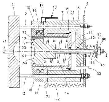
The dispensing unit 1 shown in Figures 1 to 4 comprises a normal
hot water delivery means 2 from which two cylindrical rods 3
extend towards the r-ight to support a fixed plate 4.
The rods 3 carry mounted thereon a fixed hollow body 5 provided
with a cylindr-ical inner cavity 51 in which a movable hollow body
or first hollow piston 7 slides in sealed relationship, or a f-irst
hollow piston 7 with interposed gasket 8.
From the base of the cylindrical cavity 51 their extends a conduit
52 connected to the pressurized water circuit (see Figure 8).
The first hollow piston 7 presents at one end a flange 71 which is
also mounted on the rods 3 and is connected to the plate 4 by a
first spring 72 of tension type which maintains it resting on the
body 5.
The first hollow piston or movable hollow body 7 carries upperly
fixed thereto a cylindrical jacket 73 within which a second piston
9 slides by way of an interposed gasket 10.
The second piston 9 presents an axial conduit 91 which extends to
the right into a tube 92 which sealedly passes through the base of
the first hollow piston 7 and the base of the cylindrical cavity
of the body 5 to reach beyond the plate 4; the gaskets 11 and 12
provide the seal.
The second piston 9 presents at its left end a depression 93, from
the centre of which there extends said axial conduit 91, and which
is closed by a perforated plate 94.
On the opposite end of the tube 92 there is mounted a disc 95
which acts as a support for a second spring 13 of compression type
acting between said disc and the base of the body 5.
CA 02334422 2001-02-06
_ 4 _
The disc 95 is slidablie axially on the tube 91, which has its end
externally threaded for a short distance, and is maintained in
position by a nut 96 screwed onto the tube 91.
The springs 13 and 14 are compressed to a greater or lesser extent
by screwing down the riut 96 to a greater or lesser degree.
A third spring 14 of compression type is positioned between the
base of the second piston 9 and the base of the first hollow
piston, to maintain ttie end of said the second piston at the level
of the cylindrical jacket 73 as shown in Figure 1.
The two rings 3 carry axially slidable thereon a hollow body 15
which has two cavities receiving a pair of fourth springs 16 of
compression type, and has an axial dimensional such that its left
end is flush with the cylindrical jacket 73.
An elastic pawl 17 is securely fixed to the flange 71 of the
first hollow pistons 7, and is inserted elastically into a seat
provided in the annular body 15.
The annular body 15 upperly presents a radial conduit 15 well
visible in Figure 4.
The aforedescribed uniit is shown in its rest position in Figure 1.
When it is desired to dispense espresso coffee, the elastic pawl
17 is pressed with one finger in the direction of the arrow 18, so
releasing the annular body 15 from the flange 71 of the first
hollow piston 7.
By virtue of the thrust of the fourth springs 16, the annular body
is moved into contact with the hot water delivery means 2, so
creating a cylindrical compartment 152 into which coffee powder is
fed via the conduit 151.
This position is showri in Figure 2.
CA 02334422 2001-02-06
- 5 -
When the ground coffee has been fed into said cylindrical
compartment, the service pump and the two-way valve 103 are
operated to feed pressurized water below the first hollow piston
7, this latter being ciisplaced until the cylindrical jacket 73
makes sealed contact with the wall of the distributor 2 and the
flange 71 makes contact with the annular body 15 to cause the pawl
17 to snap-operate ancl hook onto the annular body, as shown in
Figure 3.
The second piston 9 wiithdraws against the action of the third
spring 14 to maintain the coffee conveniently pressed.
The unit is hence reacly to dispense the coffee, which is achieved
by opening a timed valve 106 (Figure 8), to deliver hot water.
When delivery is complete the valve 106 returns to its initial
position, to discharge the hot water lying within the circuit
between it and the spr=ing-loaded valve 105, then the valve 103 is
again operated to return it into its initial position, and
discharge the water acting against the first hollow piston, so
enabling the first spring 72 to reposition this latter and the
annular body coupled to it as shown in Figure 1.
With reference now to Figures 5 to 7, these show the hot water
delivery means 2 with which there is associated a plate 20
provided with a central groove 21 the edges of which present two
parallel projecting ribs 22 for supporting and guiding the upper
rim 31 of a capsule 30 containing ground coffee.
Said ribs are interrupted at the position in which the capsule is
axially aligned with a cylindrical jacket 41 which projects from a
body 40 in the shape of an inverted cup corresponding to the
hollow body 5 of Figure 1 slightly modified.
This latter is sealedly mounted, via a gasket 42, on the outside
of a fixed piston 50 which is joined to the plate 20 at a precise
distance therefrom by two rods 23 on which the cup-shaped body 40
CA 02334422 2001-02-06
- 6 -
is slidingly mounted.
Two springs 51 mountecl on the rods 23 maintain the cup-shaped body
40 against the fixed piston 50, as in Figure 5.
The cylindrical jacket 41 contains a spring 42 which when in its
rest position reaches flush with the outer edge of the jacket.
The interior of the cup-shaped body communicates with the pump 101
via a conduit 44.
The interior of the cylindrical jacket communicates with the
outside via the conduit 46 through which the coffee is dispensed
into a cup.
The second embodiment of the invention operates in the following
manner.
When the dispensing unit is in its rest or standby position, it is
configured as in Figure 5. A capsule 30 is made to slide from the
outside by falling along the ribs 22 until it lies coaxial with
the jacket 41.
In this position the ribs are interrupted, and the capsule rests
on the retractable pin 23 of Figure 7.
Operation of the service pump 101 and valve 103 causes the cup.-
shaped body 40 to advance until the edge 440sealedly rests against
the edge of the perforated base 32 of the capsule 30, pressing it
in its turn sealedly against the plate 20, to attain the
configuration of Figure 6.
The retractable pin 23 is withdrawn electromagnetically when the
jacket 41 supports the capsule.
Advancement of the body 40 simultaneously causes compression of
the spring 40 against the perforated base 32 of the capsule 30.
CA 02334422 2001-02-06
- 7 -
After passing through the heater 104, hot water is delivered by
means of the pump 101 and valve 106 for a predetermined time, it
filtering through the capsule 30 to collect in the form of
espresso coffee at the exit of the conduit 46.
When this delivery has ended, it is a sufficient to halt the pump
and again switch firstly the valve 106 and then the valve 103, to
discharge firstly the excess hot water then the water contained
between the cup-shaped body 4 and the hollow piston 50, this
enabling the springs 23 to return the cup-shaped body 4 into its
initial position shown in Figure 5.
Withdrawing the cup-shaped body 4 with the relative jacket 41
disternds the spring 42 which maintains the capsule 30 perfectly
aligned with the ribs 22 along which its slides, to fall outside
the system when completely released from the jacket 41 and no
longer compressed by the spring 42.
Both the aforedescribed preferred embodiments are of horizontal
axis, however it is apparent that with a few obvious modifications
the device can also be constructed of vertical axis.