Une partie des informations de ce site Web a été fournie par des sources externes. Le gouvernement du Canada n'assume aucune responsabilité concernant la précision, l'actualité ou la fiabilité des informations fournies par les sources externes. Les utilisateurs qui désirent employer cette information devraient consulter directement la source des informations. Le contenu fourni par les sources externes n'est pas assujetti aux exigences sur les langues officielles, la protection des renseignements personnels et l'accessibilité.
L'apparition de différences dans le texte et l'image des Revendications et de l'Abrégé dépend du moment auquel le document est publié. Les textes des Revendications et de l'Abrégé sont affichés :
| (12) Brevet: | (11) CA 2334873 |
|---|---|
| (54) Titre français: | BATEAU GONFLABLE AUTOMATIQUEMENT |
| (54) Titre anglais: | AUTOMATICALLY INFLATABLE BOAT |
| Statut: | Durée expirée - au-delà du délai suivant l'octroi |
| (51) Classification internationale des brevets (CIB): |
|
|---|---|
| (72) Inventeurs : |
|
| (73) Titulaires : |
|
| (71) Demandeurs : |
|
| (74) Agent: | SMART & BIGGAR LP |
| (74) Co-agent: | |
| (45) Délivré: | 2007-02-06 |
| (86) Date de dépôt PCT: | 1999-06-23 |
| (87) Mise à la disponibilité du public: | 2000-01-06 |
| Requête d'examen: | 2001-03-02 |
| Licence disponible: | S.O. |
| Cédé au domaine public: | S.O. |
| (25) Langue des documents déposés: | Anglais |
| Traité de coopération en matière de brevets (PCT): | Oui |
|---|---|
| (86) Numéro de la demande PCT: | PCT/IB1999/001173 |
| (87) Numéro de publication internationale PCT: | IB1999001173 |
| (85) Entrée nationale: | 2000-12-11 |
| (30) Données de priorité de la demande: | ||||||
|---|---|---|---|---|---|---|
|
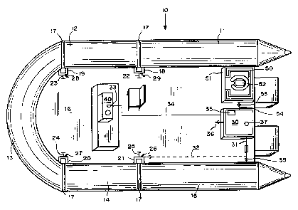
L'invention concerne un bateau (10) gonflable automatiquement, comprenant au moins deux compartiments séparés (11-15) qui sont reliés par une soupape d'intercommunication (18, 19, 20, 21) pouvant être ouverte de manière à raccorder des compartiments adjacents, ou fermée pour isoler des compartiments adjacents. Ce bateau gonflable est par ailleurs pourvu d'une pompe à gaz (30) montée de manière permanente sur ce bateau, cette pompe étant en communication fluidique avec un raccord afin de recevoir du gaz sous pression d'au moins un desdits compartiments gonflables. Cette pompe peut par ailleurs être actionnée pour gonfler automatiquement les compartiments gonflables du bateau jusqu'à une pression prédéterminée. Cette invention concerne également une enceinte gonflable (50) destinée à être gonflée et dégonflée afin de loger un individu adulte et une chaise percée (52), pour une plus grande intimité.
An automatically inflatable boat (10) including at least two separate
compartments (11-15) which are connected to one another
by an intercommunicating valve (18, 19, 20, 21) which can be opened to connect
adjacent compartments or closed to isolate adjacent
compartments. The inflatable boat is provided with a gas pump (30) permanently
mounted on the boat and in fluid communication with a
connection for receiving pressurized gas of at least one of the inflatable
compartments. The pump can be actuated in order to automatically
inflate the inflatable compartments of the boat to a preset pressure. Also
shown is an inflatable enclosure (50) which can be deflated and
inflated and to house an adult and a commode (52) to provide privacy.
Note : Les revendications sont présentées dans la langue officielle dans laquelle elles ont été soumises.
Note : Les descriptions sont présentées dans la langue officielle dans laquelle elles ont été soumises.
2024-08-01 : Dans le cadre de la transition vers les Brevets de nouvelle génération (BNG), la base de données sur les brevets canadiens (BDBC) contient désormais un Historique d'événement plus détaillé, qui reproduit le Journal des événements de notre nouvelle solution interne.
Veuillez noter que les événements débutant par « Inactive : » se réfèrent à des événements qui ne sont plus utilisés dans notre nouvelle solution interne.
Pour une meilleure compréhension de l'état de la demande ou brevet qui figure sur cette page, la rubrique Mise en garde , et les descriptions de Brevet , Historique d'événement , Taxes périodiques et Historique des paiements devraient être consultées.
| Description | Date |
|---|---|
| Inactive : CIB attribuée | 2021-01-12 |
| Inactive : CIB en 1re position | 2021-01-12 |
| Inactive : CIB attribuée | 2021-01-12 |
| Inactive : CIB expirée | 2020-01-01 |
| Inactive : CIB enlevée | 2019-12-31 |
| Inactive : Périmé (brevet - nouvelle loi) | 2019-06-23 |
| Inactive : TME en retard traitée | 2014-09-24 |
| Lettre envoyée | 2014-06-23 |
| Requête visant le maintien en état reçue | 2013-06-05 |
| Accordé par délivrance | 2007-02-06 |
| Inactive : Page couverture publiée | 2007-02-05 |
| Préoctroi | 2006-11-23 |
| Inactive : Taxe finale reçue | 2006-11-23 |
| Un avis d'acceptation est envoyé | 2006-05-29 |
| Lettre envoyée | 2006-05-29 |
| Un avis d'acceptation est envoyé | 2006-05-29 |
| Inactive : Approuvée aux fins d'acceptation (AFA) | 2006-04-28 |
| Modification reçue - modification volontaire | 2005-01-18 |
| Inactive : Dem. de l'examinateur par.30(2) Règles | 2004-07-19 |
| Lettre envoyée | 2002-02-27 |
| Inactive : Transfert individuel | 2002-01-21 |
| Modification reçue - modification volontaire | 2002-01-21 |
| Lettre envoyée | 2001-04-19 |
| Inactive : Page couverture publiée | 2001-03-30 |
| Inactive : CIB en 1re position | 2001-03-22 |
| Inactive : Inventeur supprimé | 2001-03-20 |
| Inactive : Inventeur supprimé | 2001-03-20 |
| Inactive : Lettre de courtoisie - Preuve | 2001-03-20 |
| Inactive : Notice - Entrée phase nat. - Pas de RE | 2001-03-13 |
| Demande reçue - PCT | 2001-03-08 |
| Requête d'examen reçue | 2001-03-02 |
| Exigences pour une requête d'examen - jugée conforme | 2001-03-02 |
| Toutes les exigences pour l'examen - jugée conforme | 2001-03-02 |
| Demande publiée (accessible au public) | 2000-01-06 |
Il n'y a pas d'historique d'abandonnement
Le dernier paiement a été reçu le 2006-06-07
Avis : Si le paiement en totalité n'a pas été reçu au plus tard à la date indiquée, une taxe supplémentaire peut être imposée, soit une des taxes suivantes :
Les taxes sur les brevets sont ajustées au 1er janvier de chaque année. Les montants ci-dessus sont les montants actuels s'ils sont reçus au plus tard le 31 décembre de l'année en cours.
Veuillez vous référer à la page web des
taxes sur les brevets
de l'OPIC pour voir tous les montants actuels des taxes.
Les titulaires actuels et antérieures au dossier sont affichés en ordre alphabétique.
| Titulaires actuels au dossier |
|---|
| ZODIAC HURRICANE TECHNOLOGIES, INC. |
| Titulaires antérieures au dossier |
|---|
| DOUGLAS HEMPHILL |
| GARY DALE |

