Note : Les descriptions sont présentées dans la langue officielle dans laquelle elles ont été soumises.
CA 02339256 2006-10-23
64005-843
1
DRIVE SYSTEM FOR VENEER SLICER
Technical Field
This invention relates to veneer slicers.
Background Art
Various types of veneer slicers are known. There
are, for example, the veneer slicers illustrated and
described in the following U.S. Patents: 2,576,520;
2,676,627; 3,441,069; 3,654,973; 3,680,612; 4,063,578;
4,068,693; 4,069,850; 4,083,391; 4,089,354; 4,102,372;
4,137,957; 4,503,896; 4,587,616; 4,601,317; 5,381,841;
5,511,598; 5,562,137; and, 5,590,700: Canadian Patent
1,204,985: and German Patent Specifications: 2,501,936; and,
2,523,481. There are also the disclosures of U.S. Patents:
4,392,519; 4,503,740; 4,831,747; 4,893,663; 5,067,534;
5,101,874; 5,143,129; 5,383,504; and, 5,490,548: German
Patent Specifications: 2,523,482; 3,915,516; and, 3,928,941:
and, Italian Patent Specifications: 1,084,683; and,
1,126,371. No representation is intended by this listing
that an exhaustive search of all pertinent prior art has
been made or that no better art than that listed exists, and
no such representation should be inferred. This listing
does not constitute a representation that the material
listed is pertinent, and no such representation should be
inferred.
Disclosure of the Invention
According to one aspect of the invention, a veneer
slicer comprises a frame and a flitch table for supporting a
flitch for the slicing of veneer therefrom. The flitch
table is supported from the frame. The veneer slicer
further comprises a knife. The flitch table and knife are
CA 02339256 2006-10-23
64005-843
2
relatively movable along a path toward and away from one
another. The flitch table is mounted on the frame for
movement of the flitch across the knife in cutting and
return strokes. The flitch table is supported from the
frame by a guide member secured to one of the flitch table
and the frame and a bearing member secured to the other of
the flitch table and the frame for cooperation with the
guide member. The guide member and bearing member form
between them at least one channel for a plurality of
bearings. The bearings are movable relative to the bearing
member and the guide member.
Illustratively according to the invention, the
guide member comprises a plurality of guide rails secured to
one of the frame and flitch table. The bearing member
comprises a plurality of bearing carriages secured to the
other of the frame and flitch table for cooperation with
each of the guide rails. Each bearing carriage and an
associated guide rail form at least one of said channels.
Further illustratively according to the invention,
the bearings are roller bearings.
Alternatively illustratively according to the
invention, the bearings are ball bearings.
Illustratively according to the invention, at
least one of the guide member and bearing member defines at
least one circulating channel for the ball or roller
bearings.
Additionally illustratively according to the
invention, the stroke of the flitch table during which the
knife assembly is in contact with the flitch to cut a slice
of veneer from the flitch is an upward stroke.
CA 02339256 2006-10-23
64005-843
3
Alternatively illustratively according to the
invention, the stroke of the flitch table during which the
knife assembly is in contact with the flitch to cut a slice
of veneer from the flitch is a downward stroke.
According to another aspect of the invention, a
drive mechanism for reciprocating a flitch table comprises a
drive shaft having an output end, a prime mover coupled to
the drive shaft for rotating the drive shaft, a coupler on
the output end of the drive shaft, and a connecting rod
coupled to the flitch table and the coupler.
Illustratively according to this aspect of the
invention, the drive mechanism further includes a clutch.
Further illustratively according to this aspect of
the invention, the clutch is operable selectively to cause
rotation of the drive shaft and reciprocation of the flitch
table.
Additionally illustratively according to this
aspect of the invention, the coupler includes a connecting
link. The drive mechanism further includes a counterweight
coupled to the drive shaft to counterbalance the
reciprocating/rotating mass of the flitch table, the
connecting link and the connecting rod.
Alternatively illustratively according to this
aspect of the invention, the coupler includes a flywheel.
The flywheel includes counterweight to counterbalance the
reciprocating/rotating mass of the flitch table and
connecting rod.
According to another aspect of the invention, a
drive mechanism for coupling a flitch table to a prime mover
consists essentially of a drive shaft, a throw, and a
CA 02339256 2006-10-23
64005-843
4
connecting rod. The drive shaft is coupled to the prime
mover to be driven thereby to rotate. The throw is coupled
to an output end of the drive shaft. The connecting rod
couples the throw to the flitch table.
Illustratively according to this aspect of the
invention, the drive shaft is coupled to the prime mover by
a clutch. The clutch is actuable selectively to cause
rotation of the drive shaft and reciprocation of the flitch
table.
Further illustratively according to this aspect of
the invention, a counterweight is coupled to the drive shaft
to counterbalance the reciprocating/rotating mass of the
flitch table, the throw and the connecting rod.
According to another aspect of the invention, a
drive mechanism for coupling a flitch table to a prime mover
consists essentially of a drive shaft, a flywheel, and a
connecting rod. The drive shaft is coupled to the prime
mover to be driven thereby to rotate. The flywheel is
coupled to an output end of the drive shaft. The connecting
rod couples the flywheel to the flitch table.
Illustratively according to this aspect of the
invention, the flywheel includes counterweight to
counterbalance the reciprocating/rotating mass of the flitch
table and connecting rod.
Brief Description of the Drawings
The invention may best be understood by referring
to the following description and accompanying drawings which
illustrate the invention. In the drawings:
Fig. 1 illustrates a partially fragmentary,
phantom front elevational view of a flitch table and
CA 02339256 2006-10-23
64005-843
reciprocating mechanism for a veneer slicer according to the
invention;
Fig. 2 illustrates a fragmentary sectional view of
the flitch table and reciprocating mechanism illustrated in
5 Fig. 1, taken generally along section lines 2-2 of Fig. 1;
Fig. 3 illustrates a front perspective view of a
portion of the flitch table and reciprocating mechanism with
a flitch mounted to the flitch table by upper and lower dogs
positioned to grip the flitch;
Fig. 4 illustrates a perspective view of a detail
of the system illustrated in Figs. 1-3;
Fig. 5 illustrates another perspective view of a
detail of the system illustrated in Figs. 1-3;
Fig. 6 illustrates a plan view of a detail of the
system illustrated in Figs. 1-3;
Fig. 7 illustrates an elevational view of a detail
of the system illustrated in Figs. 1-3;
Fig. 8 illustrates a plan view of an alternative
detail to the detail illustrated in Figs. 6-7;
Fig. 9 illustrates an elevational view of the
detail illustrated in Fig. 8;
Fig. 10 illustrates a partially fragmentary,
phantom front elevational view of another flitch table and
reciprocating mechanism for a veneer slicer according to the
invention;
Fig. 11 illustrates a sectional view of the flitch
table and reciprocating mechanism illustrated in Fig. 10,
taken generally along section lines 11-11 of Fig. 10;
CA 02339256 2006-10-23
64005-843
6
Fig. 12 illustrates an end elevational view of the
flitch table and reciprocating mechanism illustrated in Fig. 10,
taken generally along section lines 12-12 of Fig. 10;
Fig. 13 illustrates an enlarged view of a detail
of the flitch table and reciprocating mechanism illustrated
in Figs. 10 and 11;
Fig. 14 illustrates an enlarged, partly
fragmentary, partly vertically sectional side elevational
view of a detail of the flitch table and reciprocating
mechanism illustrated in Figs. 10-12;
Fig. 15 illustrates a fragmentary front
elevational view of the detail illustrated in Fig. 14, taken
generally along section lines 15-15 thereof; and,
Fig. 16 illustrates a fragmentary front
elevational view of a detail illustrated in Fig. 11, taken
generally along section lines 16-16 thereof.
Modes for Carrying Out the Invention
A veneer slicer of the type described in certain
of the above-identified patents, or in United States Patent
5,979,524 and United States Patent 6,102,090, is provided
for slicing veneer (not shown) from a flitch (not shown).
The flitch 11 is mounted upon the flitch table mounting
system 12 for generally up-and-down reciprocating movement
relative to a knife bar mounting system 13. The
reciprocating movement of the flitch table mounting system
12, combined with stepwise movement of the knife bar
mounting system 13 toward the flitch table mounting system
12 causes veneer to be cut from the flitch 11.
The flitch table mounting system 12 according to
the present invention includes a flitch table 14 on the back
CA 02339256 2006-10-23
64005-843
7
side (side facing away from the knife bar mounting system
13) of which are mounted multiple linear bearings 16 best
illustrated in Figs. 1-2 and 6-7 of linear motion systems
15. The linear motion systems 15 additionally include guide
rails 18 supported on an adapter frame 20, best illustrated
in Fig. 2. Mounting all of the guide rails 18 on a common
support such as frame 20 makes maintaining parallel
relationships among the guide rails 18 more straightforward.
The adapter frame 20 includes multiple vertical supports 22
which support the guide rails 18.
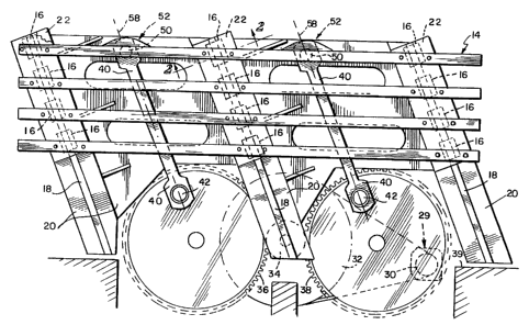
Referring now to Fig. 1, a motor 29 works through
a transmission including a drive pulley 30 and a driven
pulley 32. A drive gear 34 is coupled to driven pulley 32.
Drive gear 34 engages first and second driven gears 36, 38.
The relative circumferences and/or numbers of teeth on the
various pulleys and gears 30, 32, 34, 36, 38 reduce the
rotation frequency from that of the motor 29 to the desired
reciprocation frequency of table 12. For convenience,
driven gears 36, 38 are positioned to lie partially above a
floor level 39 and partially below the floor level 39.
First and second connecting rods 40 are pivotally
coupled to driven gears 36, 38 at points 42. Wrist pins 50
pivotally couple the connecting rods 40 to the flitch table
14 at points 52 near the upper extent of the flitch table
14.
As the first and second driven gears 36, 38 are
rotated, their rotation is converted to reciprocation of the
flitch table 14 by the connections of the connecting rods 40
and wrist pins 50. The flitch table 14 is mounted for
reciprocation by linear motion mechanisms 15. Each linear
motion mechanism 15 includes linear bearings 16 mounted on
respective ones of the three guide rails 18 in order to
CA 02339256 2006-10-23
64005-843
8
guide the flitch table 14 to reciprocate along a line of
motion 58. In the embodiment illustrated in Fig. 1, there
are three guide rails 18 and three or four linear bearings
16 are mounted on each guide rail 18. It is well within the
scope of the invention to include a flitch table mounting
system having any suitable number of linear bearings 16
mounted to any suitable number of guide rails 18.
With reference to Figs. 6-9, in the illustrated
embodiments each linear bearing 16 is formed to include a
back wall 70 for mounting on the flitch table 14 and two
sides 72. As best illustrated in Figs. 4, 5, 6, and 8, the
guide rails 18 are formed to include a top surface 80, a
bottom surface 82, and two opposite side surfaces 84. Each
side surface 84 is formed to include a groove or channel 86
therein, as illustrated in Figs. 4, 5, 6, and 8. Sides 72
of linear bearings 16 are formed to be received within
respective channels 86 formed in each side surface 84 of the
guide rails 18. Illustratively, circulating roller bearings
90 are provided between the sides 72 of linear bearings 16
and the facing surfaces of each channel 86 of guide rails
18. The roller bearings 90 circulate in respective
galleries 91 provided for circulation of the bearings 90 in
linear bearings 16. Illustratively, linear bearings 16 may
be Schneeberger Linear Technology type MRB 65 linear
bearings. Of course, ball bearings or sliding bushings can
be provided in place of roller bearings 90. If ball- or
roller bearings are used in the linear motion systems 15,
the bearings may be circulating, as illustrated, or non-
circulating. Similarly, ball- or roller bearings, whether
circulating or non-circulating, may be mounted on the rails
18 rather than on the linear bearings 16.
Referring now to Fig. 3, the flitch 11 is
illustrated mounted upon the flitch table 14. The flitch 11
CA 02339256 2006-10-23
64005-843
9
is supported by upper and lower dogs 94, 96, respectively.
Both the upper and lower dogs 94, 96 are formed to include
teeth 98 for gripping the flitch 11. The upper and lower
dogs 94, 96 are hydraulically movable along rails 99 in
order to grip the flitch 11 securely as the flitch table 14
and flitch 11 are reciprocated past a knife 100 mounted on
the knife bar mounting system 13 in order to slice veneer
from the flitch 11. Other dogging mechanisms, such as one
of the general type illustrated and described in, for
example, U.S. Patent 5,150,746, or of any other suitable
configuration, may be used instead of, or in combination
with, those illustrated in the drawings.
Another embodiment illustrated in Figs. 10-16
includes a flitch table mounting system 112 which is driven
by a single crank, rather than by the first and second
driven gears 36, 38 of the flitch table mounting system 12.
The rotation of the single crank is converted to
reciprocation of the flitch table 114 by the connection of
one connecting rod and wrist pin. The flitch table 114 is
mounted for reciprocation from any suitable number of linear
motion systems 115, for example, linear motion systems 115
including linear bearings of the general configuration of
linear bearings 16, or any other suitable configuration,
from any suitable number of guide rails having the general
configuration of guide rails 18, or any other suitable
configuration.
The flitch table mounting system 112 illustrated
in Figs. 10-16 includes a drive mechanism 110, a crank arm,
crank throw or connecting link 120 coupled to the drive
mechanism 110, a connecting rod or arm 122, illustrated in
Fig. 10 in two of its positions, attached to the connecting
link 120, and the flitch table 114 which is coupled to the
connecting arm 122. The drive mechanism 110 includes a
CA 02339256 2006-10-23
64005-843
prime mover or main drive motor (not shown), a planetary
gearbox 116, and a main drive shaft 118 connected to the
planetary gearbox 116. The connecting link 120 is coupled
to a forward, or output, end of the main drive shaft 118.
5 The connecting arm 122 is coupled to the connecting link 120
by a pin 123 and roller bearings 125. The flitch table 114
is coupled to the connecting arm 122 by a pin 127 and roller
bearings 129.
The flitch table mounting system 112 additionally
10 includes linear motion systems 115 permitting the linear
movement of the flitch table 114. The linear motion systems
115 include multiple linear bearings 126 mounted to a back
side of the flitch table 114. The linear motion systems 115
include guide rails 128 supported on multiple vertical
supports 130. The vertical supports 130 and guide rails 128
are both supported by a frame 132 which helps maintain
parallel relationships among the guide rails 128.
A planetary gearbox 116 is mounted to a base and
is coupled between the prime mover and the main drive shaft
118. The drive train for the main drive shaft also includes
a clutch and brake assembly 138. Engagement of the clutch
of assembly 138 causes the main drive shaft 118 to be driven
by the prime mover. Disengagement of the clutch of assembly
and engagement of the brake causes the main drive shaft to
stop rotating. Bearing housings 144 lie along the main
drive shaft 118. The bearing housings 144 house roller
bearings 145 to facilitate rotation of the main drive shaft
118. Each bearing housing 144 is mounted on, for example, a
welded I-beam base 150 supported on a floor 152. A
counterweight 146 is positioned along the main drive shaft
118. The counterweight 146 balances the
reciprocating/rotating mass of the flitch table 114,
connecting link 120 and connecting arm 122.
CA 02339256 2006-10-23
64005-843
11
The connecting link 120 is coupled to the opposite
end of the drive shaft 118 from the planetary gear box 116.
A first end 154 of the connecting link 120 is coupled to the
drive shaft 118. A second end 156 of the connecting link
120 is coupled to the connecting arm 122 at a pivot point
158. Connecting arm 122 is pivotally coupled to the flitch
table 114 as illustrated at 160. While the connecting link
120 is illustrated as an arm or rod, it should be understood
that, for example, a flywheel could be substituted for the
connecting link 120 or for both the connecting link 120 and
counterweight 146 in accordance with known principles.
Thus, as the main drive shaft 118 is rotated, the
connecting link 120 revolves so that pivot point 158 follows
a circular path around the axis of main drive shaft 118, as
illustrated by broken line 162. This motion is converted
into reciprocation of the flitch table 114 by the connecting
arm 122. The flitch table 114 is mounted for reciprocation
by linear motion systems 115 in order to guide the flitch
table 114 to reciprocate along a line of motion 164. In the
embodiment illustrated in Figs. 10-16, four guide rails 128
are provided with three linear bearings 126 mounted on each
guide rail 128. The remaining two linear bearing positions
126 illustrated in, for example, Figs. 10 and 12, are the
positions occupied by the upper and lower linear bearings
126 at the uppermost and lowermost positions of the flitch
table 114. It is well within the scope of the invention to
include a flitch table mounting system having any suitable
number of linear bearings 126 mounted to any suitable number
of guide rails 128.