Note : Les descriptions sont présentées dans la langue officielle dans laquelle elles ont été soumises.
CA 02340529 2001-03-12
1
Title of the Invention
Ceramic Honeycomb Structure
Background of the Invention and Related Art Statement
[0001] The present invention relates to a ceramic honeycomb
structure having a processed outer c;ircumference. In
particular, the, present invention relates to a ceramic honeycomb
structure whose outer circumference wall portion is reinforced,
which does not hinder a gas flow through partition walls in an
outer circumferential portion of the ceramic honeycomb
structure, and whose thermal shock resistance is enhanced.
[0002] A ceramic honeycomb structure is broadly used as a
substrate of a catalyst for purifying automobile exhaust gas
because of its light weight and small resistance upon gas passage.
About a shape of a cell, a square cell is employed because of
easiness of production of a die for forming and high mechanical
strength. As a material, a cordierite material whose thermal
shock resistance becomes high because of its small thermal
expansion coefficient is generally employed. In addition, as a
forming method, the extrusion forming is employed generally
because mass production is possible with the method. In recent
years, high performance of a catalyst has been expected due to
the necessity of improving purification performance of
CA 02340529 2004-04-26
2
automobile exhaust gas, and production of a ceramic honeycomb
structure having light weight and high surface area has been
expected.
[0003) However, it is generally difficult to produce the
ceramic honeycomb structure having a thickness of a partition
wall of O.lmm or less and 62 cells/cmz, or an open frontal area of
86% or more, or a bulk density of 0.26g/cm3 or less; and partition
walls near the outer circumferential wall portion are deformed.
mainly at the stage of extrusion forming and damaged easily by
pressure from circumference and a thermal shock. Therefore,
there is a problem that utility and durability as a part for
purifying automobile exhaust gas will be lost.
[ 0 0 0 4 ) Japanese Application published June 21,1982, as No. 57-99340
discloses a
ceramic honeycomb structure whose thermal expansion
coefficient is increased from the center toward an outside surface.
However, if a thermal expansion coefficient of an inside partition
wall portion is increased, it has the disadvantage of being
damaged even by a weak thermal shock.
[0005] In addition, the Japanese Published Application No. 57~
99340 discloses a method to apply a ceramic material such as
silica and alumina on partition walls of a ceramic honeycomb
structure. However, according to this method, because a great
deal ,of material which raises a thermal expansion coefficient is
applied on partition walls of the outer circumferential portion,
the inner diameter of a cell becomes smaller on partition walls of
CA 02340529 2004-04-26
3
a circumferential portion, and a pressure drop increases, too.
Therefore, there are problems that a gas flow through partition
walls in the outer circumferential portion is remarkably
decreased, and the whole catalyst cannot be effectively taken
advantage of, thereby purification performance falls.
[0006] Incidentally, a general method to carry a catalyst on a
ceramic honeycomb structure is a technique where 7 -alumina
having a large specific surface area is first turned into a water
solution to be carried on a ceramic honeycomb structure and a
noble metal catalyst is carried on the solution. If a ceramic
material such as silica and alumina which raises a thermal
expansion coefficient is applied to the partition walls at this
time, the more a quantity of the application is, the more the
water absorption ratio falls, which cause a problem that a
ceramic honeycomb structure cannot carry r -alumina uniformly,
that is, a catalyst cannot be dispersed uniformly.
[0007] Japanese Application published Oct. 8, 1981, as No. 56-129044
discloses a ceramic honeycomb structure having a high thermal
expansion coefficient in an inside partition wall portion and a
small coating thermal expansion of partition walls in an outer
circumferential portion. However, a cordierite honeycomb
structure in general use at present for automobile exhaust gas
purification is produced by taking advantage of a technique to
raise thermal shock resistance by making a thermal expansion
coefficient as a structure small by orienting a raw material by
CA 02340529 2001-03-12
a ~ 4
extrusion forming. Therefore, there is no ceramic material
having a smaller thermal expansion coefficient than the
cordierite produced through extrusion forming, and the
technique cannot be applied to a honeycomb structure whose
main material is cordierite.
Summary of the Invention
[0008] The present invention has been made in view of such
problems of prior art and aims to provide a ceramic honeycomb
structure whose outer circumferential wall. portion is reinforced,
which does not hinder a flow of gas in a circumferential partition
wall portion of the ceramic honeycomb structure, and whose
thermal shock resistance is enhanced profitably.
[0009] That is, according to the present invention, there is
provided a ceramic honeycomb structure having a plurality of
through'-holes surrounded by partition walls, wherein a thermal
expansion coefficient of an outer circumferential wall portion in
the ceramic honeycomb structure is larger than a thermal
expansion coefficient of an inside partition wall portion in a
direction of a diameter of the ceramic honeycomb structure, and
stress is applied to the inside partition wall portion from the
outer circumferential wall portion.
[0010] In the present invention, it is preferable that a
material for the outer circumferential wall portion of the ceramic
CA 02340529 2001-03-12
honeycomb structure is the same as or different from a material
for the ceramic honeycomb structure.
[0011] In the present invention, it is preferable that a
partition wall of the ceramic honeycomb structure has a
5 thickness of less than O.lmm and that the ceramic honeycomb
structure has 62 cells/cm2 or more.
[0012] In the present invention, it is preferable that the
outer circumferential wall portion is thicker than an inside
partition wall portion of the ceramic honeycomb structure.
[0013] In addition, in the present invention, it is preferable
that the ceramic honeycomb structure has an open frontal area of
86% or more.
[0014] In addition, in the present invention, it is preferable
that the ceramic honeycomb structure has a bulk density of
0.26g/cm3 or less.
Brief Description of the Drawings
Fig. 1(a)(b) are schematic views describing one
embodiment of the ceramic honeycomb structure whose outer
circumferential wall portion was reinforced with a slurried raw
material in the present invention, and Fig. 1(a) is a perspective
view of the whole, and Fig. 1(b) is an enlarged view around the
reinforceed outer circumferential wall portion.
Fig. 2(a)(b) show one embodiment of a ceramic honeycomb
CA 02340529 2001-03-12
6
structure subjected to a reinforcement process with a slurried
raw materials after the outer circumferential portion partition
walls and the outer circumferential wall portion were ground to
be removed in the present invention, and Fig. 2(a) is a
perspective diagram of the whole, and Fi;;. 2(b) is an enlarged
view around the reinforced outer circumferential wall portion.
Detailed Description of the Invention
[0015] The present invention is hereinbelow described in
detail based on embodiments shown in the drawing, but the
present invention is by no means limited to these embodiments.
[0016] Fig. 1(a)(b) are schematic views describing one
embodiment of a ceramic honeycomb structure whose outer
circumferential wall portion was reinforced in the present
invention, and Fig. 2(a)(b) show one embodiment of a ceramic
honeycomb structure whose outer circum:E'erential wall portion
was reinforced after the grinding removal in the present
invention. Fig.l(a) and Fig.2(a) are perspective views, and
Fig.l(b) and Fig.2(b) are enlarged views around the reinforced
outer circumferential wall portion; respectively.
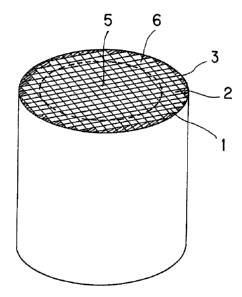
[001'7] As Figs. 1(a) and 1(b) show, in t:he present invention,
a ceramic honeycomb structure has a plurality of through-holes
(cells) 2 surrounded by partition walls 1. A thermal expansion
coefficient in an outer circumferential wall portion 3 is made
CA 02340529 2001-03-12
7
larger than that of an inside partition wall portion 5 in a
direction of a diameter of the ceramic honeycomb structure.
The ceramic honeycomb structure is in the state that stress is
applied to the inside partition wall portion 5 from the outer
circumferential wall portion 3.
[0018] In a ceramic honeycomb structure having such a
constitution, after the ceramic honeycomb structure having a
plurality of through-holes (cells '2) surrounded by partition walls
1 is first prepared, a raw material whi<:h becomes cordierite
when it is fired is slurried and applied to a circumferential
portion of the ceramic honeycomb structure to form the outer
circumferential wall portion 3. Subsequently, the ceramic
honeycomb structure is fired to make the thermal expansion
coefficient of the outer circumferential wall portion 3 of a
ceramic honeycomb structure larger than that of the inside
partition wall portion 5 in a direction of a diameter of a ceramic
honeycomb structure to put the ceramic honeycomb structure in
the state that stress is applied to the inside partition wall
portion 5 from the outer circumferential wall portion 3.
[0019] In addition, as shown in Figs. 2 (a) and 2(b), after an
outer circumferential partition wall portion 6 of a ceramic
honeycomb structure having cells 2 partitioned off by partition
walls 1 was removed by being ground, a raw material which
becomes cordierite when it is fired is slurried and applied to form
the outer circumferential wall portion 3 and fired, thereby a
CA 02340529 2001-03-12
thermal expansion coefficient of the outer circumferential wall
portion 3 of a ceramic honeycomb structure is made larger than
that of the inside partition wall portion 5 in a direction of a
diameter of the ceramic honeycomb structure to put the ceramic
honeycomb structure in the state that stress is applied to the
inside partition wall portion 5 from the outer circumferential
wall portion 3.
[0020] A basic principle and function of the present invention
are described hereinbelow. In the case that a raw material of
the cordierite; which is a general raw material for a honeycomb
structure, is subjected to extrusion forming to form a honeycomb
structure, a kaolin crystal having a hexagonal planar shape is
oriented along a face of the partition walls 1 when it passes
through a narrow slit. In the later firing step, a cordierite
crystal having a hexagonal pillar shape is generated
perpendicularly to the kaolin crystal. A thermal expansion
coefficient of the cordierite crystallization is different depending
on directions, that is, +2.9 X 10⁻⁶/°C in a direction of a diameter
and - 1.1 X 10-s/~ in a longitudinal direction. Therefore, the
honeycomb structure subjected to extrusion forming and fired
has a thermal expansion coefficient which is obtained by
synthesizing +2.9 and - 1.1 (in fact, about 0.6 X 10⁻⁶/°C ) in a
direction of a through-hole and a diameter and +2.9 X 10⁻⁶/ in a
direction of a thickness of a partition wall"
[0021] If a raw material which becomes the same cordierite is
CA 02340529 2001-03-12
. . g
slurried and applied to the outer circumferential wall portion 3
of a ceramic honeycomb structure as shown in Fig. 1(a)(b) and
Fig. 2(a)(b) and the ceramic honeycomb structure is fired by
making use of such a characteristic of a cordierite crystallization,
a thermal expansion coefficient of the outer circumferential wall
portion 3 where the slurry was applied is about 2 X 10⁻⁶/ °C
because kaolin is not oriented in the portion. Further, if this
thermal expansion coefficient is about 1 X 10⁻⁶/°C or more, the
thermal expansion coefficient is adjustable by a combination of a
raw material which becomes cordierite by being fired and other
raw material, and it can be appropriately adjusted from a
relation between a cell structure and a thermal expansion
coefficient of the inside partition wall portion 5.
[0022] Incidentally, a slurried raw material to be applied to
form the outer circumferential wall portion 3 may be a material
which becomes cordierite when it is fired, that is the same as a
raw material for a ceramic honeycomb structure, or may be
another material. That is, it may be appropriately chosen
among alumina, silicon nitride, aluminum titanate, mullite, and
materials which become these when they a3°e fired, and a slurried
material may be prepared by combining these. Therefore, a
thermal expansion coefficient of the outer circumferential wall
portion 3 can be adjusted in a moderate value from the relation
with a thermal expansion coefficient of the inside partition wall
portion 5.
CA 02340529 2004-04-26
[0023] In the stage of subjecting a raw material of cordierit~e
to extrusion forming in order to give a honeycomb shape, ravv
material particles are merely placed in line. However, when
temperature rises and reaches a firing temperature, cordierite is
5 generated, and crystals melt to be united. In the later cooling
process, the outer circumferential wall portion 3 having a large
thermal expansion coefficient is in the state that it shrinks more
than the inside partition wall portion 5 having a small thermal
expansion coefficient. That is, the ceramic honeycomb
10 structure of the present invention is in the state that a
compression effect can be obtained from outside_
[0024] In addition, cordierite is preferably applied as a
material constituting a ceramic honeycomb structure in view of
its low thermal expansion property as described above.
However, it is not limited to cordierite, and another raw material
such as alumina may be employed depending on its use.
[0025] When hot exhaust gas is suddenly sent in an automobile exhaust gas
purification apparatus in which a ceramic honeycomb structure is arranged, a
difference in temperature between a central portion and an outer
circumferential
potion is generated, and a thermal shock is applied to the ceramic honeycomb
structure. The central portion of the ceramic honeycomb structure becomes hot
and is going to expand at this time. However, it cannot expand because the
outer
circumferential portion is at normal temperature. Therefore, internal pressure
us
applied, and a tensile load is applied to the outer wall. Generally, a ceramic
is
2 5 relatively weak against a tensile load, although it is strong against a
compression
CA 02340529 2004-04-26
' 11
' load. Therefore, in the case where a tensile load in an outer
circumferential
portion due to temperature distribution exceeds rupture strength of a ceramic
honeycomb structure, the ceramic honeycomb structure is ruptured. To the
contrary, in the ceramic honeycomb structure where the outer circumferential
wall portion 3 is subjected to the specific reinforcement of the present
invention,
a thermal expansion coefficient of the outer circumferential wall portion a is
larger than that of the inside partition wall portion 5 in a direction of a
diameter.
In other words, the outer circumferential wall portion 3 is in a compressed
state,
and stress is applied toward the inside partition wall portion 5. That is,
since a
tensile load is not applied until a tensile load larger than this stress is
applied, the
outer circumferential wall portion 3 in a compressed state like the present
invention has a weaker outbreak tensile load in comparison with an outer
circumferential wall portion of a normal ceramic honeycomb structure, thereby
thermal shock resistance is increased, and rupture is hard to be caused.
[0026] Further, the present invention can be preferably
applied to a ceramic honeycomb structure having thin walls,
which has a thickness of a partition wall of O.lmm or less and 62
cells/cm2 or more, or an open frontal area of 86°/ or more, or a
25
CA 02340529 2001-03-12
x 12
bulk density of 0.26g1cm3. In addition, when a ceramic
honeycomb structure having such thin walls is produced,
deformation of a partition wall near the outer circumferential
wall portion is often caused. However, in such a deformed
ceramic honeycomb structure, the outer circumferential wall
portion having excellent thermal shock resistance can be newly
formed by grinding and removing a deformed portion. By this,
it is possible to produce a ceramic honeycomb structure having a
large surface area per unit volume and a strength by which the
structure can stand practical use and to anticipate improvement
of production yield.
[0027]
[Examples]
A specific result of operation of the present invention is
hereinbelow described.
(Examples 1 - 5, Comparative Examples 1 - 10)
A raw material which becomes cordierite when it is fired
was subjected to extrusion forming and fired to produce 30
cordierite honeycomb structures each haviing an outer diameter
of 106mm, a full length of 114mm, a thickness of partition walls
as shown in Table 1 (sample No. 1 - 7), 62 cells/cm2, and a
thickness of the outer circumferential wall. portion of 0.25mm in
each kind. Ten out of these cordierite honeycomb structures in
each kind of samples were taken out. The same raw material
was slurried as shown in Figs. 1(a) and 1(b) and applied on the
iI
CA 02340529 2001-03-12
' ' 13
outer circumferential wall portion to have a thickness of about
1.25mm. Then, the cordierite honeycomb structures were fired
to give Examples 1 to 5. Other ten cordierite honeycomb
structures were not processed at all for Comparative Examples 1
to 5. As for the other ten, in accordance with a method
disclosed in Japanese Patent Laid-Open No. 57-99340, a solution
including 10% by weight of a -alumina was passed through a
portion having a thickness of 30mm from the outer
circumferential wall portion, surplus liquid was blown off with
compressed air to dry the structures, the solution was passed
through a portion having a thickness of l5mm from the outer
circumferential wall portion, and they were dried and fired to
give Comparative Examples 6 to 10.
CA 02340529 2001-03-12
14
. r.,
ri d~ C~- CY7 C~ Cfl
c~ ~7 cV m d' cV ~t
0 0 0 0 0 0 0
c
o c~
~,.
0o N ~ ~ u~ c,~
ao co 00 00 ~ 00 00
0
~,
O
c
O O
CD CO CD Cfl CQ
47
U
'r
,?,
z
0
0 o c~ ~ o d~
00 0 ~ ~ ~:~ ~n
0 0 ,-r .-~ ,-, o
Ura'-~ O O O O O O O
rl I-~
C~
N
4.r
~"~
O
bA U O Q O O O O
O
tls C'rJ ~ l.fJC-
z
U
O
z
0 0
0
i ~,
CA 02340529 2001-03-12
[0029] A ceramic mat was wound pup around the outer
circumference of each of three kinds of the above cordierite
honeycomb structures, each of which was pressed in a can, and a
cone was attached to the can to produce a converter.
5 Combustion gas of propane gas was sent into the converter, and a
thermal shock test was conducted. ThE: temperature of the
combustion gas was 800°C at a position of the lOmm front from
the honeycomb front face. The gas was sent with a gas flow rate
of 3Nm3/min for five minutes before air at :room temperature was
10 sent for five minutes, which was regarded as 1 cycle, and each
honeycomb structure was taken out after 10 cycles to check
presence or absence of a crack. When no crack was found,
temperature of 50~ combustion gas was raised, and the above
operation was repeated in the same manner till a crack occurs.
15 Five of each kind were tested. The results are shown in Table 2.
In addition, samples of 50mm long was cut off in a right-angled
triangle section of 3.5mm and in a 3.5mm square section from a
central portion so that the outer circum:E'erential wall portion
may become an oblique side. Two of each kind of samples were
measured for thermal expansion coefficient. The results are
shown in Table 2.
[0030] Incidentally, prior to the thermal shock test, the tip of
the corn of each converter was connected to a blower to send air
at room temperature at the rate of 6 m3/min., and a difference in
pressure (a pressure drop) between in front and at the back of
i'.,,
CA 02340529 2001-03-12
16
the honeycomb structure was measured. The results are
shown in Table 2. Since Comparative Examples 1 to 5 has
completely the same honeycomb portion as Examples 1 to 5 and,
therefore, has the same pressure drop at this time, the test was
omitted except for the sample No. 1 (cell structure naming:
3/400).
[0031] In addition, about the sample No. 2 (naming of cell
structure : 3.5/400), a sample carrying 0"2g/cm3 of 7 -alumina
was prepared after the model of a catalysis, and the sample was
attached to a converter. Air at room temperature was sent to
the converter at a rate of 3 m3/min. A flow speed in a fine
portion was measured at a lOmm-backward position from an exit
end face of the honeycomb structure. The results are shown in
Table 3. In the measurement, a hot-wire anemometer of a
resistance-exothermic type having a width of the tip of a probe of
about 3mm was used.
CA 02340529 2001-03-12
17
.-....,-..~ ...~. ...,-.
0 0 0 0 0 0 0 0 0 0 0
0 o a~0 00 0 0 0 0 0
0 0 0 0 0 0 0 0 0 0
I ~ ~ I ~ ~ I
. . .~ .J '. .r . '. . ..-
. . r
.. . . c~ o c~ ,-m. co .
c~ 00 0~ .n cs~
~, 00 0o c~o co co a~ oo ~ ~o
p.,
...
~ ua o o 0 0 0 ~ ~ 00
cc~cs~cp ~.c~c~ c~J
...~ ~ rr ~r ~ rr ~r ~r
U '. o 0 0 o
~
- I I I o W .c~I I I I I I r-i
0
p U ~ ~r ~ c~ rr m c'~
0 0 0 0 0 0
.~
.N V
~,"
U U
--i i-i
U
~ .. CD O CYJ ~ ~ 00
,.., ~ ~ CYO ~ ~ LO
x
O O O r-~ O O
Q I O 1.C~O) I ~1 O C~
O O d' C'rJG~l ~H di 1tJV
m a7 O O ~ O O
'~'' V
~
C~ ~
, O
N d
C
r-i ri CD LfJ O iC:7O
09 di 00 N di L~-~'"'
GV ~ s.i ri O r~ v-~IO
N
+'
U O I I I
~ ~
r~ ~ C'rJCYJO 00 .N'L~-
E-IO ~ 00 0'J0~ CD d~ C'~p
~
~
_ C~'~
r-IO ,-I ~ O rl
.~
V
4-r
ai O
N
O O O O O O O O O O' O O O O O
C"'
~ o 0o r-o~ oo ao 0000 00 00 0000 00 ~0 00
~
;
U
,
o '
,s~
A~
,-ico c~7~ c~ o~ ~Ho~ y .c~~ . ~
m
o ~ ~ ~ ,~,~
. ,..,
+~ a~ ~C ~cm ~c ~C a~ac ~c a. ~c~c a~ ~c . ~
~' '.n
0
t'~S~ C~ GZ P i~ ~ ~ S3 C~ '
Q" , , .~ ~
~i
~
W
zs o W o o W o o W o o ~~ o o W o o ,.,
W ~
~ U U U U U U U U U U U s~,
.
c~
~
b o
o o a~ a~
o
~
tw o 0 0 0 0 ~ aA
~
~ o ~ 0 0 0
~
+.~
~ _ ~ ~ ~ U
V 1fJ N
"..S'
CrJ ~ dr ~ L~
z
r-i cV c0 ~ u~
'~
o o
z
CA 02340529 2001-03-12
18
0 o c~
~ c~i d'
p c~ ~
U
00 0
0
0 c~
c~c
...
0
o ,..
g ~ .,
0
W
~
0
i
,-
a~
E-~ ...r
a~ ~c
W
o
~ ~ a.
~'
W
W o
0
~U
~d W
.,..,
0
O
z~
U
O
'
O
~z
a
o
a
CA 02340529 2001-03-12
19
[0034]
(Example 6, Comparative Example 11)
The same raw material which beconnes cordierite when it
is fired was subjected to forming and fired to obtain 20 cordierite
honeycomb structures, each having a full length of 114mm, a
thickness of a partition wall of 0.05mm, and 186 cellslcm2. Ten
among them were ground by a grinder having a diamond grinding
stone so that the outer diameter of llE~mm after firing was
reduced up to the outer diameter of 105mm. The same raw
material was slurried and applied to the cordierite honeycomb
structures to form the outer circumfere:ntial wall portion as
shown in Figs. 2(a) and 2(b). The cordierite honeycomb
structures were fired again to give "Example 6" having an outer
diameter of 106mm. A thickness of the outer circumferential
wall portion at this time was not uniform, a reason of which is
that the outer circumferential portion partition wall after being
ground has a form of the teeth of a comb, and the average was
about l.7mm. The other ten were employed as "Comparative
Example 11". At this time, the outer diameter was 106mm, and
the thickness of the outer circumferential wall was 0.2mm.
Seven of each kind were subjected to the aforementioned thermal
shock test and measured for thermal expansion coefficient. The
results are shown in table 4.
CA 02340529 2001-03-12
[0035]
Table 4
Thermal expansion
coefficie
Thermal (10~61~ ) I
shock
test
(~)
Kind Average Outer
Central
of Range circumferential
rupture wall portion Portion
Example 6 880 850 - 900 1.60, 1.67 0.38, 0.44
Comp. Ex. 11 810 750 - 850 0.35, 0.41 0.35, 0.43
a ~ ~ i
[0036] In addition, an aluminum board is abutted against an
5 individual end face of two kinds of the aforementioned cordierite
honeycomb structures of Example 6 and Comparative Example 11
by means of an urethane sheet having a thickness of about
0.5mm, and the side was wrapped in a tube having a thickness of
about 0.5mm to be sealed up. They were put in a hydraulic
10 container, and water pressure was raised by degrees till a sound
of rupture could be heard to rupture the samples.
Pressures at this time are shown in Table 5. Incidentally, the
number of the tested samples is three in e<~ch Example.
[0037]
15 Table 5
External pressure
strength test
(MPa)
Kind
Average of
rupture Range
Example 6 1.21 1.03 - 1.52
Comp. Ex. 11 0.55 0.45 - 0.62
CA 02340529 2001-03-12
21
[00 38]
(Study)
As is apparent from the above results, any Example of the
present invention showed a dominant value in the thermal shock
test and an external pressure strength test in comparison with
Comparative Examples, and a superior effect of the present
invention could be confirmed.
[0039] As discussed above, in the ceramic honeycomb
structure whose outer circumferential wall portion was subjected
to a specific reinforcement of the present invention, a pressure
drop is not increased, a flow of gas is not abnormally
concentrated in the center, and thermals shock resistance is
improved. In addition, about the ceramic honeycomb structure
having a thin partition wall and a wide surface area per unit
volume, a product having excellent thermal shock resistance can
be provided likewise, which is useful when it is used for an
automobile exhaust gas purification apparatus, or the like,
having relatively severe use conditions.