Note : Les descriptions sont présentées dans la langue officielle dans laquelle elles ont été soumises.
CA 02344006 2001-06-04 SG Ln~~~ C'~
~ method and apparatus for compacting a powder material into a homogenous
article
TECHNICAL AREA
The present invention relates to a method and an apparatus for compacting a
powder
material into a homogenous article.
BACKGROUND TO THE IN«ENTION
In processes for manufacturing articles, such as bearing rings, bushes, solid
bodies,
etc, by compacting po~.vder materials in a moulding cavity it is essential
that the
powder be evenly distributed within the moulding cavity before the start of
the
pressing operation. However, it is difficult to lilt a moulding cavity with
powder so
1 ~ that the particles in the powder are uniformly distributed and so that the
upper sur-
face of the powder material filling the moulding cavity is horizontal.
Moreover, if
the pressing operation takes place with a very high pressing rate so that the
pressing
time is in the order of a few milliseconds it is a great risk that air is
entrapped in the
compacted article, disW rbing the homogeneity thereof.
The object of the present invention is to solve these problems by providing a
method
and an apparatus for compacting a powder material into a homogenous article in
which the particles in the powder are evenly distributed within the moulding
cavity
and the upper surface of the powder in the moulding cavity is horizontal
before the
2~ start of the pressing step.
SLiWiVIARY OF THE INVEN'T'ION
This object is accomplished by a method for compacting a powder material inta
a
homogenous article, characterised by the steps of;
placing the powder material in a. moulding cavity connected to a gas source,
CA 02344006 2001-06-04
blowing gas into the lower end of the moulding cavity so that the particles in
the
powder material are suspended. n a gas stream,
sealing the upper end of the moulding cavity by an upper pressing punch,
connecting the lower end of the moulding cavity to a vacuum source,
sealing the connection to the vacuum source by moving a lower punch relative
to
the lower end portion of the moulding cavity, and
thereafter compacting the powder material with the help of the pressing punch.
In a preferred embodiment the vacuum source creates a sub-pressure in the
mould-
ing cavity of at least half the atmospheric pressure.
The invention relates also to an arpparatus for compacting a powder material
into a
homogenous article comprising a moulding cavity having vertical side walls and
open ends, and an upper and a lower punch having the same cross-sectional area
as
1 ~ the moulding cavity and being movable into and out of the moulding cavity,
char-
acterised in that an opening is arranged in the side wall of the moulding
cavity in the
lower end part thereof, said opening being connected to a device for blowing
gas
into and a device: for sucking g<zs out of the moulding cavity, and that the
lower
punch is movable relative to thc: moulding cavity from a first position in
which the
upper end surface of the punch is located below the opening and a second
position
in which the opening is covered by the side wall of the lower punch.
In a preferred embodiment a gas-pervious membrane covers the opening, said mem-
brane being impervious for the smallest of the particles in the powder
material to be
2~ placed in the moulding cavity. Preferably, the vertical walls of the
moulding cavity
consist of the inner wall of a matrix having the form of a hollow cylinder and
the
side wall of a cylindrical core pin concentrically located in the inner space
defined
by the hollow matrix, and the upper and lower punch has a lower respectively
an
upper end surface comprising a_n annular flange .fitting into the annular
moulding
cavity, the opening connected to a device for blowing gas into and a device
for
CA 02344006 2001-06-04
sucking gas out of the moulding cavity comprising an annular groove in the
lower
end portion of the inner wall of the matrix anc~'or the side wall of the core
pin.
BRIEF DESCRIPTION OF THE DR~WINC~
The invention will now be described with reference to the enclosed Figures, of
which;
Fig. 1 schematically shows a cross-sectional view of an apparatus according to
a
preferred embodiment of the invention, during the fluidising step,
Fig. 2 shows the apparatus of Figure 1 during the vacuum step, and
Fig. 3 shoes the apparatus of Figure l, immediately before the start of the
compact-
1 ~ ing step.
DESCRIPTION OF EMBODII'rIENTS
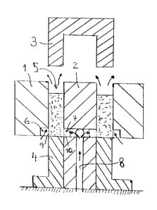
An apparatus for compacting powder into solid annular articles, such as
bearing
?0 rings, is shown in Figures 1-J. The apparatus comprises a hollow
cylindrical matrix
l, a core pin ?, an upper pressing punch 3 and a lower punch 4. The core pin 2
is
cylindrical and concentrically disposed in relation to the matrix 1 so that
the side
walls of a moulding cavity 5 is detined by the inner wall of the matrix and
the side
wall of the core pin. The bottom wall of the moulding cavity 5 is defined by
the up-
?5 per end surface of the lower punch 4 having the form of a hollow cylinder
fitting
into the annular space between the inner side wall of the matrix and the side
wall of
the core pin. The upper punch p has the form of a hollow cylinder with a
closed up-
per end.
30 The matrix 1 has an annular groove 6 in the lower end portion thereof. The
groove 6
is by suitable conduits in communication with a gas source (not shown in the
Fig-
CA 02344006 2001-06-04
ores j. Opposite to the groove 6 a similar annular groove 7 is made in the
core pin 2.
This groove 7 is also in communication with the gas source by suitable
conduits. In
the embodiment shown the groove 7 is connected to a central bore ~ by at least
two
radial bores. The central bore 8 is by a suitable conduit connected to the
same gas
source as the groove b. The side of the respective groove 6,7 that is turned
against
the moulding cavity ~ is closed by a gas-permeable membrane 9 and 10, respec-
tively.
In Figure 1 the apparatus is shown in the beginning of the compacting process
im-
mediately after powder matez-ial has been introduced into the moulding cavity
5. In
order to accomplish an even distribution of the particles in the powder
material
filled into the moulding cavity, gas is blown into the moulding cavity by the
gas
source, as is indicated by arrows in Figure 1. The flow rate of the gas is
such that a
fluidised bed is accomplished, i.e. the particles in the powder material are
suspended
1 ~ by the gas flow. Thereby an even distribution of the particles in the
powder material
and a horizontal upper particle surface will be established. The flow rate for
creating
a fluidised bed i;> dependent of the density, size and form of the particles
in the
powder material.
In the described embodiment the gas flow is created after the filling of the
moulding
cavity with powder material. When the gas flow first reaches the bottom of the
moulding cavity., it has a stirring ei:fect on the powder material in the
moulding cav-
ity that ensures an even distribution of the particles in the powder material
when a
flow rate sufficient for suspending the paz-ticles of the powder material is
reached. It
2~ is pointed out that the flow rate should be successively increased in order
to avoid a
sudden increase of pressure in the moulding cavity, which might result in that
some
of the particles in the moulding cavity will be thrown out from the moulding
cavity.
Alternatively, the gas flow in the moulding cavity is created immediately
before the
moulding cavity is filled with powder material. In such a case, the pressure
drop
CA 02344006 2001-06-04
over the moulding cavity will successively increase during the tilling of the
mould-
ing cavity so there will be no risk of a Sudden pressure increase therein.
In the case when the filling of the moulding cavity takes place before the gas
flow is
created, the lower punch ~ is preferably moved upwards from the position shown
in
Figure 1 so that the upper surface of the powder material filled into the
moulding
cavity will lie Hush with the nipper surfaces of the core pin and the matrix.
Superflu-
ous powder material tilled into the moulding cavity can then be scraped of.
There-
after, the lower punch is moved downwards to the position shown in Figure 1
and
the gas flow is c-reated.
The gas used can be air or an inert gas.
After having achieved a fluidising of the particles in the moulding cavity 5,
the gas
1 ~ flow is stopped. At the same tune the upper punch 3 is moved downwards
into the
upper end of annular space so that the upper end of this space is sealed of
from the
surrounding atmosphere. The grooves 6 and 7 are put in communication with a
vac-
uum source (not shown in the Figures). The gas in the moulding cavity will
thus be
drawn out thereof and the evenly distributed particles in the powder material
filling
the mould will come into abutment with each other. The sub-pressure created in
the
moulding cavity is at least half the atmospheric pressure. It is pointed out
that the
membranes 9,10 is so fine that no particles can pass through the membranes
into the
grooves 6,7. This step in the process of compacting a powder material into a
ho-
mogenous article; is shown in Figure 2, the sucking of gas out of the moulding
cavity
2~ being indicated by arrows.
In order to ensure the sealing oil the moulding cavity from the surrounding
atmos-
phere during the during the si.ib-pressure step, it usually appropriate to
provide
sealing elements (not shown in the figures) between the matrix and the upper
and
~0 lower punch, respectively. The sealing element for the lower punch is
preferably
fixed to the matrix whereas the sealing eiement for the upper punch is
slidably at-
CA 02344006 2001-06-04
b
tacked to the upper punch and pretensioned to a position in which the sealing
ele-
ment lies flush with the lower surface of the upper punch.
Thereafter, the lower punch ~. is moved upwards such a distance that the
grooves 6,7
are covered by the outer side wall thereof and the grooves 6, 7 are
disconnected from
the vacuum source. The powder material in the moulding cavity will move
upwards
together with thf: Lower punch ~~ and in the end position of the lower punch,
which is
shown in Figure 3, the upper surface of the powder material is in abutment
with the
lower end surface of the upper punch 3.
The apparatus is now ready for the compacting of the powder material in the
moulding cavity and a the pressing punch 3 is driven downwards with a force P,
as
indicated by an arrow in Figure .3. The pressing punch is driven with a very
high
pressing rate, thf; pressing operation will only take a few milliseconds.
1J
The lower punch 4 is advantageously arranged to eject the compacted article
out of
the moulding cavity ~ after the pressing step has been performed.
In the embodiment described opsnings 9,10 are present in both the matrix and
the
core pin. In an alternative embodiment (not shown), the openings are only
provided
in the matrix. In such a case it is possible to make the matrix movable in
relation to
the lower punch in order to open and close this opening. Such an alternative
would
facilitate the support of the lower punch during the pressing operation.
?5 As stated in the beginning, the invention can also be performed for
compacting arti-
cles into solid bodies, such as a cylinder. In such a case, the apparatus does
not in-
clude a core pin :~o that openings would only be present in the matrix, which
then
preferably is movable in relation to the lower punch in order to close and
open the
openings to the moulding cavity.
CA 02344006 2001-06-04
i
The embodiment described can be modified in several ways within the scope of
the
invention. The 'moves 6,7 can for example be connected to different gas and
vac-
uum sources, but preferably they are connected to the same gas and vacuum
source.
The respective gas and vacuum source can for example be the outlet and the
inlet,
respectively of a blower but it ..s also possible to use separate sources for
creating
the flow of gas and the vacuurr~. Moreover, the moulding cavity can have
another
form so that arti~~les with other shapes than rings can be made, for example
tubes
with a rectangular or L.~-shaped section. 'The invention should therefore only
be re-
stricted by the wording of the enclosed patent claims.