Note : Les descriptions sont présentées dans la langue officielle dans laquelle elles ont été soumises.
CA 02345796 2001-03-29
D E S C R I P T I 0 N
LID MEMBER FOR FOOD CONTAINER
[TECHNICAL FIELD]
The present invention relates to a lid member for food container,
more particularly, to an improvement of a lid member to be used for
containers for quickly cookable foods.
[BACKGROUND ART]
Conventionally, quickly cookable foods like chow mein, spaghetti,
polished rice and sekihan (steamed rice with red beans) or the like have
been distrubued as a sort of quickly cookable foods to be cooked by
pouring thereinto hot water, leaving it for predetermined time and
removing therefrom the hot water.
As the containers for quickly cookable foods to be cooked by
removing such poured hot water, their popular structure have cup-shaped
container body and plastic lid member mounted thereon. Container bodies
for such container were usually produced by thermoforming expanded resin
particles (expandable resin beads) made of polystyrene resins and
blowing agent like butane, pentane or the like. Then, the popular
plastic lid members are sheet-form and have discharge apertures at their
outer circumference. These plastic lid member is simply to cover the
container body, more particularly, the lid member is engaged with the
container body through their projections by engaging such projections
with grooves provided on the flange at.the outer circumference of the
lid member.
With reference to Fig.7, the conventional plastic lid member 100
have a pair of apertures in mutually opposite positions at their
-1-
CA 02345796 2001-03-29
circumference edge. These apertures are to discharge the poured hot
water from the container body and have slit blade a. When these blade a
is stood up, apertures to discharge the hot water from the container are
formed.
However, numbers of such apertures to be formed at a restricted area
in the flange are limited, therefore, discharging rate of the hot water
is accordingly limited, thus, it usually takes the longer time to remove
hot water. Then, when apertures are blocked by the foods in the
container, the further longer time will also be necessary to remove the
hot water. Further, when the blade a is broken, their fragments might
be entered into the container. Further, sealability of the container is
not well, thereby, moisture might penetrate into the container through
space formed by standing up blade a and that formed between the lid and
the container covered thereby.
In addition thereto, since most of such conventional lid members 100
were sheet-form products, when the container body is covered therewith,
figure of the container became unfavorable due to their bulk, and
further space was necessary in transportation or storage thereof.
Further, in consideration of the consumers' interest expressed and
increased recently on an environmental issue, it is not preferable to
dump these plastic lid members.
Then, when such containers were not handled well at the discarding
of the hot water, the lid member is disconnected from the container body,
and food stuff together with hot water will then be spilt therefrom.
Accordingly, there is a pot,ential danger of suffering from burning, and
it is necessary to securely hold both of the container and the lid
member at such discharging step.
Incidentally, Japanese Utility Model Publication No. 61-3810 (Prior
Art) discloses a container for quickly cookable foods utilizing a lid
-2-
CA 02345796 2001-03-29
member made of paper. This utilizes paper as base layer and is to
stick to the opening of the container.
With reference to Fig.8, lid member 200 has substantially the same
circumference figure with that of the opening in the container body,
then the discharge apertures 204 appear on the surface of the lid by
pulling up the tab 203 integrally formed on the member 200.
The lid member 200 is formed by laminating polyethylene, aluminum
foil or the like onto the base paper. In the container wherein the lid
member 200 is stuck to the container body, the discharge apertures 204
are formed by pulling up the tab 203 integrally formed on the lid member
200, then, the easily-peelable area D is separated from the slit linking
both foot-ends b, b around the tab 203.
The lid member 200 according to the prior art is suit to seal the
container than the conventional lid member 100 (Fig. 7), and it reduces
the bulk of the container, thereby, they are easily manufactured and
dumped. According to this structure, however, the tab 203 may be broken
at the slit linking both ends b, b when the tab 203 is pulled.
Then, the tab 203, positioned opposite to the tab 202, is placed
around the center in the circumference edge of the easily-peelable area
D, therefore, it is necessary to pull up the tab 203 to open the
apertures, such that pulling force should be applied radially and
equally toward the tab 203 as a center. Accordingly, considerable force
and knack were necessary to separate the easily-peelable area D, thereby,
the tab 203 itself may be broken at such peeling step.
In view of such inconveniences in the prior arts, the present
invention is to provide a lid member for a container of quickly cookable
foods which can discharge hot water, in particular, it has excellent
sealability with a container body, it allows to discharge hot water
safely and rapidly, its discharging apertures are easily formed, and it
-3-
CA 02345796 2006-09-14
can be easily dumped as waste.
[SUMMARY OF THE INVENTION]
Nith reference to Figs. 1 to 3, a lid member for food container
(hereinafter simply referred to as "lid member") according to the
present invention which can discharge hot water is a lid member 1
wherein it has substantially the same circumference figure with that of
a opening 15 and will be stuck to the opening 15 of a container body 14,
and it has a layered structure in which a base layer 20 and a surface
sheet 40 are laminated through an adhesive layer 30.
The lid member 1 has an easily-peelable area A of the layered
structure having lubricant 11 additionally between the base layer 20
and the surface sheet 40, a non-peelable opening area C of the
aforenoted layered structure placed within the easily-peelable area A, a
non-peelable area B of the aforenoted layered structure placed adjacent
to the the easily-peelable area A, and the lid member further has
a first tab 2 to peel off the lid member I from the container body
14, and
a second tab 3 formed at the side on the easily-peelable area A
along the boundary line between the non-peelable area B and the easily-
peelable area A to open the discharge apertures of the opening area C by
peeling off from the lid member l a surface sheet in the easily-peelable
area A.
Then, the lid member 1 comprises a series of slits 4-6, wherein:
a first slit 4 which cut from the base layer 20 to the adhesive
layer 30 and forms discharge apertures in the opening area C,
a second slit 5, which cut from the surface sheet 40 to the adhesive
layer 30, along the boundary line between the easily-peelable area A and
non-peelable area B, and
-4-
CA 02345796 2006-09-14
a third slit 6, whichiscutfrom the base layer 20 to the adhesive
layer 30, is placed where the second tab 3 is mounted, fromthe
foot-end d of the second tab 3 spaced from the second slit 5 to the
intersection e with the second slit 5.
According to the lid member of the present invention, the surface
sheet in the easily-peelable area A can be easily and securely
peeled along with the second slit 5 by pulling up the second tab 3,
thereby, desired number of discharge aperture(s) can be formed.
According to the other embodiment of the present invention, with
reference to the Fig. 1(B), a lid member is arranged so that at least a
part of the third slit 6 in the lid member 1 is placed on the sticking
portion 17 substantially corresponding to the circumference edge of the
opening 15.. In this case, preferably, the cross position e by the
second slit 5 and the third slit 6 is placed on the sticking portion 17.
By arranging the third slit 6 like that, since the surface sheet 40
can be peeled smoothly from the base layer 20 along the third slit 6
while the second tab 3 can also be peeled completely, the second tab 3
can easily be pulled.
According to the another embodiment of the present invention, with
reference to the Fig. 4(A), a lid member can be arranged so that the
second slit is at least one slit zone 50 wherein a pair of discontinuous
slits inclinating mutually outwardly make a row along the boundary line
and between the easily-peelable area A and the non-peelable area B.
Thus, when the second slit is the slit zone 50, since the second tab
3 breaks the slit zone 50 going through the adjacent slits succesively,
the surface sheet 40 in the easily-peelable area A can easily be
separated, and the discharge apertures can also be opened more smoothly.
According to the another embodiment of the present invention, with
reference to the Fig. 5, a notch 18 is formed around the second tab 3
-5-
CA 02345796 2006-09-14
and is formed from the circumference edge of the lid member to
the second slit 5 (the slit zone 50) or to around the second
slit 5.
Thereby, by pulling up the second tab 3, after the
notch 18, the third slit 6 and the second slit 5 (the slit
zone 50) are broken in this order, the surface sheet 40 in the
easily-peelable area A is peeled from the base layer 20.
In particular, when the notch 18 is formed from the
circumference edge of the lid member to the cross position e
(See Fig. 3) by the second slit 5 and the third slit 6,
peeling of the easily-peelable area A with the second tab 3
would remarkably be easy.
Certain exemplary embodiments may provide a lid member
for a food container having substantially the same
circumference as that of an opening of a container body of a
food container and having a layered structure in which a base
layer and a surface sheet are laminated through an adhesive
layer, wherein the lid member comprises: an easily-peelable
area of the layered structure having a lubricant between the
base layer and the surface sheet, a non-peelable opening area
of the layered structure disposed within the easily-peelable
area; a non-peelable area of the layered structure disposed
adjacent to easily-peelable area, the lid member further
comprising: a first tab to peel off the lid member from the
container body, a second tab formed on the easily-peelable
area along the boundary line between the non-peelable area and
the easily-peelable area to open the apertures of the opening
area, a first slit, cut from the base layer to the adhesive
layer forming apertures in the opening area, a second slit,
cut from the surface sheet to the adhesive layer, along the
boundary line between the easily-peelable area and non-
peelable area, and a third slit, cut from the base layer to
the adhesive layer and disposed where the second tab is
-6-
CA 02345796 2006-09-14
mounted, from a foot-end of the second tab, spaced from the
second slit, to an intersection with the second slit.
[BRIEF DESCRIPTION OF THE DRAWINGS]
Fig. 1(A) and (B) respectively show a plan view and a
back view of the lid member according to an embodiment of the
present invention.
Fig. 2 (A) and (B) respectively show a cross sectional
view taken along the lines X-X and Y-Y in the Fig. 1.
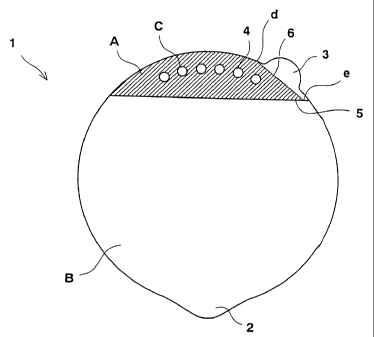
Fig. 3 is a schematic view showing the area (A) to (C)
appeared on the surface of the lid member according to an
embodiment of the present invention.
Fig. 4 (A) and (B) respectively show a plan view and a
partially enlarged view of the lid member according to the
other embodiment of the present invention.
Fig. 5 shows a back view of the lid member according to
another embodiment of the present invention.
Fig. 6 is a perspective view showing as to how to use a
food container employing the lid member according to an
embodiment of the present invention.
Fig. 7 shows a plan view of the conventional plastic lid
member.
Fig. 8 shows a plan view of the conventional paper lid
member.
- 6a-
CA 02345796 2001-03-29
[BEST MODE FOR CARRYING OUT THE INVENTION]
Detail of the present invention will be described as follows.
With reference to Figs. 1-3, in general, a lid member of the present
invention is the lid member 1 having layered structure in which the base
layer 20 and the surface sheet 40 are laminated through the adhesive
layer 30, in other words, the lid member 1 is stuck to the opening 15 of
the container body of food container and have substantially the same
circumference edge with that of the opening 15.
Interlayer between the base layer 20 and the surface sheet 40 of
the lid member I is sectioned into the easily-peelable area A having
the layered structure in which the lubricant 11 is further applied to
facilitate to peel the base layer 20 from the surface sheet 40, the
non-peelable opening area C to form the apertures to discharge the hot
water placed in the easily-peelable area A, and the non-peelable area B
positioned adjacent to the easily-peelable area A.
Both the opening area C and the non-peelable area B have the
aforenoted layered structure wherein the base layer 20 and the
surface sheet 40 are arranged so that they can not be peeled from each
other.
Then, the first slit 4 is formed in the opening area C which cuts
from the base layer 20 to the adhesive layer 30. It is preferably that
transverse cross-section to be made by the first slit 4 should be a
little larger than that of the opening region C.
Then, the circumference edge of the lid member has at least two tabs
of the first tab 2 to peel the lid member 1 from the container body 14
and of the second tab 3 to form the apertures to discharge the hot
water in the opening area C by peeling the surface sheet in the easily-
peelable area A of the lid member 1. The first tab 2 is preferably
provided on the non-peelable area B, while the second tab 3 is usually
-7-
CA 02345796 2006-09-14
provided at the side of the easily-peelable area A and at adjacent to
the boundary line between the non-peelable area B and the easily-
peelable area A. Lid member 1 can have one or more first tab(s) 2,
while, with regard to the second tab 3, it can have one or two tab(s) 3
when the lid member I has single second slit S.
Further, the second siit 5, which cuts from the base layer 20 to
the surface sheet 40, is formed straightly substantially along the
boundary line between the easily-peelable area A and the non-peelable
area B which is adjacent to the area A and on such boundary line or in
the easily-peelable area A.
And, the third slit 6, which cuts from the base layer 20 to the
adhesive layer 30, is formed around the second tab 3 fromthe
circumferential edge d of the lid member (one of foot-ends of the second
tab 3) spaced from the second slit 5 to the intersection e of the
second slit 5.
Then, with reference to Fig. 1(B), the sticking portion 17 of the
lid member I is provided at a position to be contacted with the opening
of the container body, and width of an adhesion zone in the sticking
portion 17 is usually 1-10mm. Preferably, a part of the third slit 6 is
placed on the sticking portion 17. Specifically, the cross position e
by the second slit 5 and the third slit 6 is preferablly placed on the
sticking portion 17. Meanwhile, these slits 4, 5 and 6 may either be
continuous liner slits or discontinuous slits like perforated slits.
The second slit 5 may be the slit zone 50 as illustrated in Fig. 4.
In this case, with reference to Fig. 4, the stits 5a are arranged in
rows as discontinuous pairs of slits which are mutually looking
outwardly and have inclination of approximately 20 degree on the
peeling direction (pull direction). Slits 5a may be arranged as two or
more rows. Then, when the slits 5a are formed as discontinuous pairs of
_g_
CA 02345796 2001-03-29
slits which are mutually looking outwardly and are arranged
symmetrically, slits can be broken easily, and fragments of the base
layer at the broken sites can also be prevented. Although the slits
5a may be arranged in two or more rows, in view of ideal peeling, it is
preferable to arrange it in 3-5 rows. In this case, preferably, the
slit zone 50 is formed on the boundary line between the easily-peelable
area A and the non-peelable area B.
As illustrated in Fig.5, a notch 18 may further be provided on the
second slit 5 (the slit zone 50) or in adjacent thereto within the
circumference edge of the lid member. In this case, the notch 18, which
cuts from the surface sheet 40 to the base layer 20, is provided such
that slit of several mm length from the circumference edge of the lid
member is laid from the circumference edge of the lid member 1 to the
second slit 5. And, preferably, the notch 18 is arranged to lay from
the circumference edge of the lid member to the third slit 6 (the cross
position e in Fig. 3) on or along the second slit 5. Meanwhile, if the
notch 18 is simultaneously prepared with a knife to make the second slit
or the third slit 6, difference on the mutual position can be adjusted.
The present lid member will then be explained along with production
method thereof.
As the base layer 20, any layered structure prepared by extruding
sealant 10 onto the aluminum foil 9 is applicable. As the sealant 10,
any sealant which is easily peeled from the container body 14 made from
resin like expanded styrol, styrol and polypropylene is applicable, and
includes, for example, those having cold adhesion like olefin resin such
as ethylene covinyl acetate (EVA), polyolefin resin such as ethylene
vinyl alcohol acetate (EVOH) or heat seal varnish may be used.
As the surface sheet 40, paper 7 of 60 g/mZ thickness or more, in
particular, coat paper of about 60 to about 150 g/mZ thickness is
_g_
CA 02345796 2001-03-29
applicable. Both sides of the paper 7 are processed according to the
identical step in the gravure printing method, whereby printing layer 12
with ink is coated on the front side, and lubricant 11 (thickness of
about 0.2 to about 20gm) containing a mixture of an edible surfactant
agent such as lecithin, digestive cotton adhesive, wax or silicon or the
like is coated on the area corresponding to the easily-peelable area A
in the back side.
Further, for the adhesive layer 30, adhesive 8 which is excellent in
heat bonding at the surface coated by the lubricant 11, in particular,
polyethylene, ethylene methacrylic acid (EMA) or the like is applicable.
Laminated products having layered structure [of base layer 20 -
adhesive layer 30 - surface sheet 40] can be produced by laminating,
with an extruder, the base layer 20, the surface sheet 40 and the
adhesive layer 30 sandwiched therebetween. Each of slits and notch were
provided.with or without cutting previously the laminated products into
leaf-like form, then the lid member 1 is produced through clicking
process with or without minutely cutting them previously. Each of slits
and notch are simultaneously formed at the minute cutting step or the
drawing process. Each slit can be formed respectively in the separate
process.
For example, the second slit 5 (the slit zone 50) can be made on the
surface sheet 40 prior to the lamination. Likewise, the slits 4 and 6
can also be made prior to the lamination. In this case, however, the
slits 4, 5 and 6 have to be cut in the form of the perforated line (not
in the continuous line).
The lid member 1 so produced is stuck to the opening 15 of food
container 14 by means of heat seal or the like.
As the food container 14, container made from various kinds of
materials including expanded styrol, styrol, polypropylene and paper can
-10-
CA 02345796 2001-03-29
be used.
Using method of a container employing the lid member of the present
invention will be described as follows.
First of all, the first tab 2 is pulled up, then one third of the
lid member 1 is peeled toward opposite direction from the opening 15,
and hot water is poured into the container body 14.
Next, the first tab 2 is bent over circumference edge of the
container body 14 to reseal the container, and it is left for the
determined time. After then, the easily-peelable area A is peeled
(the fragment 16 is removed) by pulling up the second tab 3, then the
apertures 13 is opened, and unnecessary hot water is discarded as
illustrated in Fig. 6.
Example 1
The base layer 20 was produced by applying sealant 10 (25,u m
thickness) made from cold adhesive EVA (olefin resin) to aluminum foil 9
(15u m thickness). On the other hand, rolled paper 7 (coated paper:
84.9g/mz) was processed according to the identical step in the gravure
printing method, whereby the printing layer 12 with ink was coated on
the front side, and lubricant 11 prepared by mixing an edible surfactant
agent with silicon was coated on the back side, thereby, the surface
sheet 40 was produced.
Next, laminated products having layered structure [of base layer
20 - adhesive layer 30 - surface sheet 40] were produced by laminating,
with an extruder, the base layer 20, the surface sheet 40 and the heat
adhesive polyethylene 8 (adhesive layer 30 with thickness of 15u m
thickness) sandwiched therebetween.
Then, slits and notch were provided by cutting the laminated
products into leaf-like form, then the lid member 1 was produced through
-11-
CA 02345796 2001-03-29
minute cutting and drawing process.
The third slit 6 was arranged such that at least a part of the slit
6 is laid on the sticking portion 17, and the third slit 6 is laid
from the circumferential edge d (one of foot-end d of the second tab 3)
in adjacent to the second tab 3 spaced from the second slit 5 to the
cross position e(about 3mm inside from the outer circumference) by the
second s l i t 5 (See F ig. 3) .
This lid member was stuck to the sticking portion 17, in 4mm width,
of the cup-shaped container body made-of polystyrene paper.
Thus, a container for quickly cookable foods (the container for
quickly cookable noodle) according to the present example was produced.
As illustrated in Figs. 2 and 3, slits according to this example
included circularly perforated line employed as the first slit 4 and
straight line slits employed as the second and the third slits 5 and 6.
Example 2
Laminated products were produced according to the procedures same to
those in Example 1 except that EVOH was used as the sealant 10, then
slits were provided by cutting them into leaf-like form, and the lid
member 1 was produced through minute cutting and drawing process.
This lid member was stuck with heat-fusing to the cup-shaped
container body made of polystyrene paper.
Continuous curve slits were employed as the first slits 4 and 6, and
the slit zone 50 consisting of slits 5a inclined to mutually look
outwardly were employed as the second slit 5 as illustrated in Figs. 4
(A) and (B) .
Thus, a container for quickly cookable foods (the container for
quickly cookable noodle) according to the present example was produced.
-12-
CA 02345796 2001-03-29
[INDUSTRIAL APPLICABILITY]
According to the lid member of the present invention, desired
number of apertures can be formed, thereby, blockage of the apertures by
the foods in the container are prevented, and the hot water can rapidly
be removed. Then, since the fragments of the lid member to be made at
the forming of the apertures are adhered and peeled with the back
surface of the surface sheet as an opening area in the non-peelable
area B, any fragment (blade) might not be entered into the container,
thereby, sanitory lid member would be provided.
Lid member according to the present invention is formed by layered
products consisting mainly of paper, therefore, bulk of container at
transportation or storage are reduced, then, compact and aesthetic lid
member and.container can be provided.
Further, sealability of the container is improved by heat-sealing
the lid member to the container body, thereby, spilling of contents is
effectively prevented when the hot water is discarded from the container.
In addition, the lid member according to the present invention may
be dumped as combustibles and as garbage.
Then, the lid member according to the present invention will
eliminate breaks of the tab to open apertures for discharging hot water,
which are problems in the conventional paper lid member, and provide a
container for quickly cookable foods in which the surface sheet can be
smoothly peeled.
Further, according to the lid member of the present invention, the
surface sheet will be peeled more correctly and easily by providing the
notch on the circumference edge of the lid member and using it as an
origin for peeling the surface sheet.
-l3-