Note : Les descriptions sont présentées dans la langue officielle dans laquelle elles ont été soumises.
CA 02350088 2010-06-01
1
BACKGROUND OF THE INVENTION
1. Field of the Invention
The present invention relates generally to flexible
circuits and methods for manufacturing such circuits, and
more particularly to printed circuit board assemblies
including optical fiber connectors and a flexible optical
circuit. Even more specifically the present invention
relates to the use of flexible optical circuits with
strain relief arms. These arms assist in both mounting
the flexible circuit to a circuit board or optical
connector, and also in absorbing any forces acting on the
flexible circuit thereby preventing damage to the optical
fibers.
2. Brief Description of Earlier Developments
Many present day telecommunications systems, computer
systems, etc. transmit and/or process both electrical
signals and optical signals. Typically, optical signals
are routed via optical fibers over relatively long
distances in order to increase the transmission speed and
efficiency relative to the propagation of electrical
signals. In contrast, much of the signal processing
analysis and storage is performed electrically. Thus,
these systems frequently convert optical signals to
electrical signals, and electrical signals to optical
signals.
Many of these systems, include a number of printed
1781305.1
CA 02350088 2010-06-01
2
circuit boards or cards which plug into a back plane or
mother board. The back plane generally provides power as
well as a reference voltage or ground to each of the
printed circuit boards. In addition, the back plane
provides a pathway by which the printed circuit boards
communicate with each other.
These types of circuit assemblies include optical
connectors and flexible optical circuits which are
secured optically via optical fibers to the optical
connectors. Quite often either an optical disconnect and
resulting data loss occurs in the system or even total
failure of the optical system occurs due to a sudden
strain type force (i.e. something that snags or pulls on
the flexible circuit). It is an advantage of the present
invention to define a flexible optical circuit, method of
manufacturing such a circuit and printed circuit
assembly employing the flexible optical circuit, which
includes a strain relief feature to avoid this type of
optical disconnect issue.
Examples of some references which describe technology in
the similar technical areas of this application include
U.S. Patent No. 4,496,215 (a flexible fiber optic cable
for connecting an optical transmitter to an optical
sensor in an electronic assembly), U.S. Patent No.
5,204,925 (a flexible optical circuit having tab portions
where the optical fibers terminate), U.S. Patent No.
5,259,051 (apparatus and method of making optical fibers)
and U.S. Patent No. 6,005,991 (printed circuit board
assembly having a flexible optical circuit).
1781305.1
CA 02350088 2010-06-01
3
SUMMARY OF THE INVENTION
In accordance with one aspect of the present
invention, there is provided a printed circuit board
assembly comprising:
a printed circuit board;
an optical fiber connector adapted to be secured to
the printed circuit board; and
a length of a flexible optical circuit having a
number of optical fibers therein, one end portion of the
length including a tab element which is secured to the
optical fiber connector and includes at least one strain
relief arm that projects from the one end portion and is
adapted to be secured to the optical fiber connector.
In accordance with another aspect of the present
invention, there is provided a flexible optical circuit
comprising:
at least one optical connector; and
a length of a flexible material having a number of
optical fibers therein, one end portion of the length
including a tab element which is secured to the connector
and includes at least one strain relief arm that projects
from the one end portion, the tab element and the at least
one strain relief arm adapted to be secured to the optical
connector.
1781305.1
CA 02350088 2010-06-01
4
In accordance with a further aspect of the present
invention, there is provided a method of fabricating a
flexible optical circuit comprising the steps of:
providing a plurality of optical fibers extending
between first and second end portions of a length of
flexible material, this length of flexible material
having at one end portion a flexible tab element in
combination with at least one flexible strain relief
arm;
mounting an optical connector to the flexible tab;
and
securing the at least one flexible strain relief
arm to said optical connector.
BRIEF DESCRIPTION OF THE DRAWINGS
The foregoing aspects and other features of the present
invention are explained in the following non restrictive
description of illustrative embodiments thereof, taken
in connection with the accompanying drawings, wherein:
Fig. 1 is a perspective view of a portion of a
conventional optical cable assembly;
Fig. 2 is a partial perspective view of a printed circuit
board assembly that is plugged into a back plane;
1781305.1
CA 02350088 2001-06-07
Fig. 3 is a partial plane view of a flexible optical
circuit with a tab element adapted to be secured to a
connector;
Fig. 4 is a partial plane view of a flexible optical
circuit having strain relief arms flanking the tab
element in accordance with the features of the present
invention; and
Fig. 5 is a partial plane side view of a flexible optical
circuit secured to a connector, the circuit having strain
relief arms positioned to be secured to the connector in
accordance with the features of the present invention.
DETAILED DESCRIPTION OF THE PREFERRED EMBODIMENT
Although the present invention will be described with
reference to the embodiments shown in the drawings, it
should be understood that the present invention can be
embodied in many alternate forms of embodiments. In
addition, any suitable equivalent size, shape or type of
elements or materials could be used.
Referring to Fig. 1, there is shown a perspective view of
a conventional optical fiber connector 10. The connector
can be part of a cable assembly 12 which may utilize
an optical fiber ribbon cable 14. The cable assembly 12
could include additional components. The cable 14
generally comprises optical fibers 16 (typically having a
core and cladding material), a buffer material (not
shown), strengthening material (not shown), and a jacket
or cover 18. The cover 18 is removed at the end 20 of
the fibers 16 passing through the ferrule 26. Any
suitable optical fiber cable could be provided. In this
CA 02350088 2001-06-07
6
embodiment the end 20 of the fibers 16 are aligned in a
row for engaging a mating optical connector.
The connector 10 generally comprises a subassembly 22 and
a connector housing 24. The subassembly 22 generally
comprises the end 20 of the fibers 16, a ferrule housing
25, a locator 27 (see Fig. 2), and guide pins 28. The
connector housing 24 generally comprises a coupling body
30, a coupling sleeve 32, a carrier sleeve 33, and an end
sleeve 34. A similar connector housing is described in
U.S. Patent No. 5,828,805 which is hereby incorporated by
reference in its entirety. However, in alternate
embodiments any suitable type of connector housing could
be provided. The subassembly 22 is fixedly connected to
the coupling body 30. The coupling body 30 is fixedly
connected to the coupling sleeve 32. The coupling sleeve
32 is movably mounted on the carrier sleeve 33 and biased
by a spring (not shown) in a forward direction. The
coupling sleeve 32 includes lips 36. The end sleeve 34
is connected to the carrier sleeve 33 and surrounds a
portion of the cable 14.
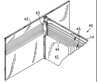
Referring now to Fig. 2 a printed circuit board assembly
40 according to an embodiment of the present invention is
illustrated. The printed circuit board assembly includes
a printed circuit board 41 that is illustratively plugged
into a back plane or motherboard 42. The printed circuit
board generally includes a number of electrical contacts
or connections for making electrical contact with the
corresponding connectors 43 on the back plane. The
printed circuit board assembly also has a connector for
establishing optical communication with one or more
optical fibers routed along the back plane. The printed
circuit board assembly 40 includes a flexible optical
CA 02350088 2001-06-07
7
circuit 44 disposed upon the printed circuit board 41.
The flexible optical circuit includes a flexible sheet of
conductive material in which is embedded a plurality of
optical fibers 45. The flexible optical circuit can, for
example, include a pair of flexible sheets of conductive
material with the optical fibers being sandwiched
therebetween. The flexible sheets can be formed of many
different conductive materials such as for example MYLAR
or KAPTAN. The thickness of the flexible sheets can vary
so as to modify the degree of flexibility of the flexible
optical circuit:, The flexibility of the flexible optical
circuit varies inversely with respect to the thickness of
the flexible sheets. Flexible circuits formed of MYLAR
sheets having a thickness of about 6 mils has been found
to be very suitable.
As stated, the flexible optical circuit 44 includes a
number of optical fibers 45 embedded in the flexible
material. For example, the optical fibers 45 can be
secured between flexible sheets by means of an adhesive
such as a pressure sensitive adhesive. The flexible
optical circuit 44 is typically mounted to the printed
circuit board 41 in a variety of ways. Example of
various known methods that the flexible optical circuit
can be mounted to the printed circuit board include by
means of hold down clips, mechanical standoffs or
adhesive. Alternatively, the flexible optical circuit
can be positioned within a rigid structure that is, in
turn, mounted to the printed circuit board. The flexible
optical circuit is supported relative to the printed
circuit board by means of optical connectors 43 mounted
on the ends of the optical fibers such as, for example,
the type of optical connector as shown in Fig. 1.
CA 02350088 2001-06-07
8
As shown in Fig. 3 a conventional flexible optical
circuit 44 having a plurality of optical fibers 45
embedded therein includes a flexible tab element 46 that
is secured to an optical connector at the end portion of
flexible element 46. Such a flexible circuit is shown,
for example, in U.S. Patent No. 5,259,051, herein
incorporated by reference. If a sudden strain type force
were to be felt by flexible circuit 44, i.e. a force that
tugs or otherwise exerts a pulling force on the flexible
circuit, an optical disconnect can occur in the system
with resulting` loss in data. In accordance with the
specific features and advantages of the present invention
and as shown in Fig. 4, there is included along with the
flexible optical circuit a strain relief feature that
will prevent the negative effects of a sudden strain
force on the flexible circuit. As illustrated in Fig. 4
flexible optical circuit 44 having a plurality of optical
fibers 45 embedded therein can include tab element 46,
the end portion thereof which secures the flexible
optical circuit 44 to a connector. The strain relief
feature is illustrated in the form of strain relief arms
47 which are positioned in a flanking relationship to tab
element 46. Generally speaking, the strain relief feature
could be at any location on circuit 44 that is devoid of
fibers 45. In accordance with the preferred embodiments
of the present invention two strain relief arms
positioned in flanking relationship to tab 46 are
employed to achieve the desired advantages as described
herein. However, it is to be understood that in
accordance with the present invention at least one strain
relief arm can be used to achieve the desired results.
The arms once secured as explained hereinbelow prevents
any strain on the flexible circuit from effecting the
optical fibers on the tab.
CA 02350088 2001-06-07
9
In accordance with the features of the present invention
any optical connector that can be optically secured to a
flexible optical circuit can be used with the present
invention. Examples of optical connectors include the
various optical connectors described herein.
Fig. 5 illustrates one example of a preferred mechanism
for securing flexible strain relief arms 47 to optical
connector 48. Optical connector 48 includes means for
securing each strain relief member thereto. In the
specific example illustrated in Fig. 5, the connector
includes means" for securing each strain relief arm
thereto. A preferred means for accomplishing this result
in accordance with the present invention is mounting
element 49 which is positioned on the bottom portion of
each optical connector. Each mounting element 49
includes a peg mounting member 50 positioned so as to be
projecting away from connector 48. One embodiment of the
present invention is to employ preexisting pegs on the
connector for securing the strain relief member.
However, if the connector does not include any pegs
thereon it is within the scope of the present invention
that., pegs could be added to the connector. In the
alternative, for example, the flexible circuit could be
mounted to the circuit board by using any suitable and
known fastening means that could be used for this
purpose. Since one embodiment of this invention has two
strain relief arms 47 flanking the tab element 46, each
optical connector includes two mounting elements 49, each
having a peg mounting member 50 projecting therefrom. To
secure the flexible circuit 44 to optical connector 48,
peg mounting members 50 can be inserted within each one
of the openings 51 located within strain relief arm 47.
In order to form a printed circuit board assembly
CA 02350088 2001-06-07
= ~ y
C
exhibiting the unique features and advantages of the
present invention, the combined optical flexible circuit
44 and optical connector 48 can also be secured together
to a printed circuit board. This can be achieved by
inserting each peg mounting member 50 first in each
corresponding opening 51 located in each flexible strain
relief arm 47, and then into each corresponding opening
52 located in circuit board 53.
In another embodiment, the peg mounting member 50 can be
positioned through pre-existing openings in the flexible
strain relief"' arms 47 and circuit board 53.
Alternatively, there can be no pre-existing openings and
each peg mount member 50 can include, for example, a nail
like end portion so that each peg could be forced through
arms 47 or board 53. In both situations, however, the
peg mounting members 50 will fit through holes in the
arms 47 and/or board 53. When optical connector 48 is
pressed inwardly to insert each peg mounting member 50
into the opening into each arm 47, it will capture each
flexible strain relief arm 47 under the optical
connector. The bottom portion of the connector could
include a recessed portion that is shaped to receive the
portion of the flexible circuit under the connector for
the purpose of maintaining height configurations.
Capturing arms 47 in the manner described above will make
the flexible optical circuit "pull proof", i.e. if one
happens to snag onto the flexible circuit and pull on the
circuit you will not disconnect any of the fibers from
the circuit thereby avoiding optical disconnect. The
arms will transfer the pulling force to the peg mounting
members projecting from connector 48.
CA 02350088 2001-06-07
11
It is also within the scope of the present invention to
employ other means that will secure the flexible strain
relief arms to the bottom portion of connector 48 without
using peg mounting members 50. It is clearly intended in
according with the scope of the present invention to
employ any other equivalent mounting mechanism for this
purpose.
It should be understood that the foregoing description is
only illustrative of the invention. Various alternatives
and modifications can be devised by those skilled in the
art without dearting from the invention. For example,
the present invention has been described at various
portions herein as an optical flexible circuit. However
the present invention could be used on an electrical
flexible circuit. Accordingly, the present invention is
intended to embrace all such alternatives, modifications
and variances which fall within the scope of the appended
claims.