Sélection de la langue

Search

Sommaire du brevet 2350886 

Énoncé de désistement de responsabilité concernant l'information provenant de tiers

Une partie des informations de ce site Web a été fournie par des sources externes. Le gouvernement du Canada n'assume aucune responsabilité concernant la précision, l'actualité ou la fiabilité des informations fournies par les sources externes. Les utilisateurs qui désirent employer cette information devraient consulter directement la source des informations. Le contenu fourni par les sources externes n'est pas assujetti aux exigences sur les langues officielles, la protection des renseignements personnels et l'accessibilité.

Disponibilité de l'Abrégé et des Revendications

L'apparition de différences dans le texte et l'image des Revendications et de l'Abrégé dépend du moment auquel le document est publié. Les textes des Revendications et de l'Abrégé sont affichés :

  • lorsque la demande peut être examinée par le public;
  • lorsque le brevet est émis (délivrance).
(12) Brevet: (11) CA 2350886
(54) Titre français: COUVERCLE POUR INTERRUPTEUR MONTE SUR VEHICULE
(54) Titre anglais: COVER FOR VEHICLE CONTROL SWITCH
Statut: Réputé périmé
Données bibliographiques
(51) Classification internationale des brevets (CIB):
  • H01H 9/22 (2006.01)
  • H01H 3/20 (2006.01)
(72) Inventeurs :
  • BREMNER, RONALD DEAN (Etats-Unis d'Amérique)
  • DYBRO, NIELS (Etats-Unis d'Amérique)
(73) Titulaires :
  • DEERE & COMPANY (Etats-Unis d'Amérique)
(71) Demandeurs :
  • DEERE & COMPANY (Etats-Unis d'Amérique)
(74) Agent: BORDEN LADNER GERVAIS LLP
(74) Co-agent:
(45) Délivré: 2004-04-13
(22) Date de dépôt: 2001-06-15
(41) Mise à la disponibilité du public: 2001-12-16
Requête d'examen: 2001-06-15
Licence disponible: S.O.
(25) Langue des documents déposés: Anglais

Traité de coopération en matière de brevets (PCT): Non

(30) Données de priorité de la demande:
Numéro de la demande Pays / territoire Date
60/211,982 Etats-Unis d'Amérique 2000-06-16

Abrégés

Abrégé anglais


A cover is provided for a control switch in a vehicle that is movable between
open and closed positions. In the cover open position, the switch paddle is
freely
accessible. In the cover closed position, the switch paddle is partially
covered to limit
access to the paddle and alert the operator to thereby avoid unintended
actuation of
the switch. In the closed position, the paddle is still accessible if needed
to actuate
the switch in an emergency without first opening the cover.

Revendications

Note : Les revendications sont présentées dans la langue officielle dans laquelle elles ont été soumises.


CLAIMS
1. A vehicle control switch and cover assembly comprising:

a housing;

a switch mounted in the housing and having a paddle member movable
by an operator to one of multiple positions to control a vehicle function; and
a cover movably mounted to the housing far movement between open
and closed positions, the cover in the open position enabling unrestrained
access to
the paddle and the cover in the closed position partially blocking access to
the
paddle to prevent unintended movement of the paddle by the operator;
wherein the switch paddle is disposed in a recess in the housing and
the cover in the closed position partially covers the recess and does not
substantially
extend from the recess.

2. The vehicle control switch and cover assembly as defined by claim 1
wherein the paddle is movable in opposite directions from a center biased
position.

3. The vehicle control switch and cover assembly as defined by claim 2
wherein the cover in the closed position covers the paddle from one direction.

4. The vehicle control switch and cover assembly as defined by claim 2
wherein the switch and paddle are located at the upper front corner of the
housing
and the paddle is accessible from above to move the paddle forward and
accessible
from the front to move the paddle rearward.

5. The vehicle control switch and cover assembly as defined by claim 4
wherein the cover when in the closed position covers the paddle from above.

6. The vehicle control switch and cover assembly as defined by claim 2


wherein the cover is rotatably mounted to the housing to move between the open
and closed positions.

7. The vehicle control switch and cover assembly as defined by claim 1
wherein the cover has a leg portion adjacent the paddle when the cover is in
the
closed position wherein movement of the paddle in one direction also moves the
cover to the open position.

8. The vehicle control switch and cover assembly as defined by claim 1
further comprising a snap engagement device operable between the housing and
the
cover to retain the cover in the closed position.

9. A vehicle control switch and cover assembly comprising:

a housing;

a switch mounted in the housing and having a paddle member biased
to a center position and movable by an operator in opposite directions to
control a
vehicle function; and,

a cover movably mounted to the housing for movement between open
and closed positions, the cover in the open position enabling unrestrained
access to
the paddle and the cover in the closed position partially blocking access to
the
paddle to prevent unintended movement of the paddle by the operator;
wherein the switch paddle is disposed in a recess in the housing and
the cover in the closed position partially covers the recess and does not
substantially
extend from the recess.

10. The vehicle control switch and cover assembly as defined by claim 9
wherein the switch and paddle are located at the upper front corner of the
housing
and the paddle is accessible from above to move the paddle forward and
accessible
from the front to move the paddle rearward.

11. The vehicle control switch and cover assembly as defined by claim 10


wherein the cover when in the closed position covers the paddle from above.
12. The vehicle control switch and cover assembly as defined by claim 11
wherein the cover has leg portion adjacent the paddle when the cover is in the
closed position wherein movement of the paddle rearward also moves the cover
to
the open position

13. The vehicle control switch and cover assembly as defined by claim 9
wherein the cover is rotatably mounted to the housing to move between the open
and closed positions.

14. The vehicle control switch and cover assembly as defined by claim 9
wherein the cover has a leg portion adjacent the paddle when the cover is in
the
closed position wherein movement of the paddle in one direction also moves the
cover to the open position.

15. The vehicle control switch and cover assembly as defined by claim 9
further comprising a snap engagement device operable between the housing and
the
cover to retain the cover in the closed position.

16. A vehicle control switch and cover assembly comprising:

a housing;

a plurality of switches mounted in the housing and each having a
paddle member, the switches being center biased switches in which the paddles
are
movable forward and rearward by a vehicle operator to control a vehicle
function;
and,

a cover movably mounted to the housing for each switch for movement
between open and closed positions, the cover in the open position enabling
unrestrained access to the paddle and the cover in the closed position
partially
covering a respective paddle to alert the operator and thereby prevent
unintended
movement of the paddle by the operator;


wherein the paddles are located in a recess in the housing and the
cover closes the recess from above while leaving the paddle open from the
front.

17. The vehicle control switch and cover assembly as defined by claim 16
wherein each cover covers a paddle from above and prevents unintended movement
of the paddle rearward.

Description

Note : Les descriptions sont présentées dans la langue officielle dans laquelle elles ont été soumises.

CA 02350886 2001-06-15
COVER FOR VEHICLE CONTROL SWITCH
BACKGROUND OF THE INVENTION
1. Field of the Invention
The present invention relates to ofif road vehicles such as agricultural or
construction tractors in which the operator has one or more switches that are
used to
control various machine functions such as, but not limited to, controlling the
hydraulic
system. Often these switches are located on the armrest of the operator's seat
for
easy access by the operator.
2. Description of Related Art
In a work vehicle, such as a tractor, an array of identical switches may be
provided to operate different portions of the hydraulic system. These switches
may
be actuated to turn on or off various functions during the operation of the
machine.
Inadvertent deactivation of a switch or inadvertent activation of a switch by
improper
finger placement can result in an undesired machine function and a loss of
productivity. For example, when planting with an air seeder, one switch
controls the
seeder blower fan motor. Actuation of the switch to interrupt the air
distribution while
planting has time consuming consequences. On the other hand, an adjacent or
nearby switch actuates the hydraulics to raise or lower the implement during
headland turns and thus must be available for activation.
To avoid inadvertent actuation of a switch, it is been known to provide plugs
that can be inserted on a switch to restrict movement of the switch.
Unfortunately,
when it is necessary to actuate the switch, the plug must first be removed and
the
switch actuated. This can be a time consuming process and undesirable in an
emergency situation.
SUMMARY OF THE INVENTION
The present invention seeks to overcome the disadvantages in the prior art by
providing individual covers far each switch within the housing in which the
switch is
1

CA 02350886 2001-06-15
mounted. Each cover can be moved to an open position providing free access to
its
respective switch. Alfiernatively, the cover can be rotated to a closed
position in
which the switch is covered in such a way as to prevent inadvertent actuation
of the
switch. However, in the preferred embodiment, when the cover is in the closed
position, access is still provided to the switch to move the switch to
deactivate a
machine function. Thus, any function can be stopped without first uncovering
the
$wltCh.
Each cover has a hook like detent feature at one end that engages with a
portion of the armrest housing to secure the cover in the closed position to
avoid
1o movement of the cover by excessive vibration, etc. One or more of the
covers can be
provided with a raised or recessed portion to provide a tactile feedback to
the
operator as to which switch the cover is associated so that the operator can
properly
place his or her fingers on the switch covers by feel rather than by sight.
DESCRIPTION OF THE DRAWINGS
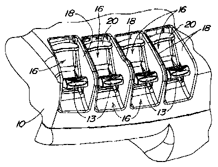
Fig. 1 is a perspective view of a vehicle armrest showing switches with the
covers of the present invention in open positions in which the switches are
uncovered.
Fig. 2 is similar to Fig. 1 showing the covers in the closed position.
2o Fig. 3 is a sectional view showing one switch and the cover in the open
position.
Fig. 4 is a sectional view like Fig. 3 showing the switch with the cover in
the
closed position.
Fig. 5 is a perspective view of a cover according to the present invention.
DESCRIPTION OF THE PREFERRED EML34DIMENT
Fig. 1 shows the armrest 10 of a working vehicle that has an array of paddle
switches and covers according to the present invention. The armrest 10
includes four
paddle Switches 12 generally identical to one another. The paddle switches 12
are
located toward the forward end of the armrest and have paddles 13 movable by
an
operator in opposite directions as shown by the arrow 14 in Fig. 3. The
paddles 13
2 -


CA 02350886 2003-07-07
are located in recesses 16 in the armrest housing such that they are generally
within
the armrest housing rather than protruding therefrom. The recesses are
separated
by divider walls 18. A cover 20 according to the present invention is
associated with
each switch 12. While the invention is shown with switches in an armrest
control, it
will be appreciated that the switches can be located elsewhere in a vehicle
cab.
The covers 20 are mounted to the armrest housing for rotation about the pivot
post 22 shown in Figs. 3-5 and further described in connection with Fig. 5. In
Fig. 2,
the covets 20 are shown rotated to closed positions in which they cover the
paddles
13 by closing the recesses 16 from above. The front of each recess 16 remains
open
so that the paddles can be pushed rearward to rotate the paddles counter
clockwise
as viewed in Fig. 4 so that a machine function can be turned off quickly
without first
moving the cover to its open position. Each cover 20 extends rearward through
an
opening 24 in the armrest housing as shown in Fig. 3. The rear portion 26 of
the
cover is formed with a recess 28 that receives a hook 30 in the armrest
housing to
form a snap fit of the cover in the closed position covering the paddle 13.
This
provides a positive engagement of the cover to prevent unintended movement of
the
cover to the open position by vibration or inadvertent touching by the
operator.
To facilitate moving the cover to the open position, the top of the cover is
formed with a recess 32 to apply a downward force to disengage the hook 30 and
easily return the cover to the open position. In addition, one or more of the
covers
can include a raised protrusion 34 toward the front of the cover that provides
a tactile
feedback to the operator.
In a preferred embodiment, the armrest housing and the covers 20 are
molded plastic components but can be made of other materials as well.
In a preferred embodiment, the switches 12 are center biased with the
paddles in the position shown in the Figures and movable in opposite
directions as
shown by the arrow 14 of Fig. 3. In operation during air seeding, one switch
is used
to activate the blower fan, another switch activates the seed meters and a
third
switch raises and lowers the seeder. The fan and seed meters are turned on and
the
seeder is lowered into the ground. The operator will close the cover 20 on the
switch
that controls the blower fan. When the end of the row is reached, the other
two
3

CA 02350886 2001-06-15
switches are pulled rearward to raise the seeder and stop the seed meter. It
is critical
that the blower fan not be turned off. Turning off the blower fan can cause
the seeder
to plug and require extensive down time to clean. Thus, the cover 2Q on the
fan
switch is closed to prevent inadvertently turning off the fan. However, the
paddle is
open on the front and, in the event of an emergency requiring the operator to
turn off
the blower fan, the paddle can be accessed and the switch turned off without
first
moving the cover.
The cover has a top portion 36 and a front leg 38 that extends downward to a
forked end 40 having side arms 42 on either side of the respective paddle. The
pivot
posts 22 are integrally formed in the side arms 42. Ths front leg 3$ is
positioned
adjacent the paddle 13 of the respective switch as shown in Fig. 4 so that the
cover
moves to the open position in the event the switch must be turned off suddenly
without first moving the cover to the open position.
The cover of the present invention operates to prevent unintended actuation
of the switch but is not a lock out that prevents actuation. The switch can
still be
accessed and turned off even when covered. The cover, when closed, alerts the
operator that the switch is not to be actuated in the normal course of
operation.
The advantages of the cover of the present invention is that it can be used to
eliminate inadvertent actuation of the switches, provide positive placement of
the
operator's fingertips, includes a detent mechanism to hold the cover in place
to
prevent movement of the cover due to vibration, individual covers are provided
for
each switch, and each switch can be quickly moved to an off position without
first
moving the cover to the open position.
4

Dessin représentatif
Une figure unique qui représente un dessin illustrant l'invention.
États administratifs

Pour une meilleure compréhension de l'état de la demande ou brevet qui figure sur cette page, la rubrique Mise en garde , et les descriptions de Brevet , États administratifs , Taxes périodiques et Historique des paiements devraient être consultées.

États administratifs

Titre Date
Date de délivrance prévu 2004-04-13
(22) Dépôt 2001-06-15
Requête d'examen 2001-06-15
(41) Mise à la disponibilité du public 2001-12-16
(45) Délivré 2004-04-13
Réputé périmé 2006-06-15

Historique d'abandonnement

Il n'y a pas d'historique d'abandonnement

Historique des paiements

Type de taxes Anniversaire Échéance Montant payé Date payée
Requête d'examen 400,00 $ 2001-06-15
Enregistrement de documents 100,00 $ 2001-06-15
Le dépôt d'une demande de brevet 300,00 $ 2001-06-15
Taxe de maintien en état - Demande - nouvelle loi 2 2003-06-16 100,00 $ 2003-06-13
Taxe finale 300,00 $ 2004-01-28
Taxe de maintien en état - brevet - nouvelle loi 3 2004-06-15 100,00 $ 2004-05-25
Titulaires au dossier

Les titulaires actuels et antérieures au dossier sont affichés en ordre alphabétique.

Titulaires actuels au dossier
DEERE & COMPANY
Titulaires antérieures au dossier
BREMNER, RONALD DEAN
DYBRO, NIELS
Les propriétaires antérieurs qui ne figurent pas dans la liste des « Propriétaires au dossier » apparaîtront dans d'autres documents au dossier.
Documents

Pour visionner les fichiers sélectionnés, entrer le code reCAPTCHA :


Pour visualiser une image, cliquer sur un lien dans la colonne description du document. Pour télécharger l'image (les images), cliquer l'une ou plusieurs cases à cocher dans la première colonne et ensuite cliquer sur le bouton "Télécharger sélection en format PDF (archive Zip)" ou le bouton "Télécharger sélection (en un fichier PDF fusionné)".

Liste des documents de brevet publiés et non publiés sur la BDBC .

Si vous avez des difficultés à accéder au contenu, veuillez communiquer avec le Centre de services à la clientèle au 1-866-997-1936, ou envoyer un courriel au Centre de service à la clientèle de l'OPIC.


Description du
Document 
Date
(yyyy-mm-dd) 
Nombre de pages   Taille de l'image (Ko) 
Description 2001-06-15 4 184
Abrégé 2001-06-15 1 13
Revendications 2001-06-15 4 127
Dessins représentatifs 2001-11-20 1 18
Revendications 2003-07-07 4 131
Description 2003-07-07 4 185
Dessins 2001-06-15 3 83
Page couverture 2001-12-07 1 44
Dessins représentatifs 2004-03-12 1 20
Page couverture 2004-03-12 1 46
Cession 2001-06-15 5 150
Poursuite-Amendment 2003-01-16 3 110
Poursuite-Amendment 2003-07-07 7 245
Correspondance 2004-01-28 1 25