Note : Les descriptions sont présentées dans la langue officielle dans laquelle elles ont été soumises.
CA 02353337 2001-07-20
BACKGROUND OF THE INVENTION
'This invention relates to brackets and more particularly to a bracket for
supporting
an upright rod to which a number of horizontal rails can be attached. This
invention also
relates to a temporary barrier which includes the combination of the bracket,
upright rod and
rails.
The majority of accidents that occur on a site where buildings are being
constructed
result from falls. Houses under construction, for example, have many openings
for such
things as stairs and windows and usually the openings remain clear and
unobstructed until
the construction is substantially complete when the windows and stairs are
installed.
Frequently workmen on the site accidentally fall through such openings with
resulting injury
or even death.
The conventional practice is to construct temporary barriers to prevent
accidental
falls. The barriers usually consist of two or more horizontal pieces of timber
which are nailed
to the frames of the openings. In the course of construction, however, the
barriers must be
removed to allow material or equipment to be passed through the openings.
Afterward, the
barriers must be replaced but frequently they are not and the openings are
then a hazard for
workmen who are working on the site.
Temporary barriers are usually not replaced because of the inconvenience in
doing
so. The pieces of timber which make up the barrier may split when the barrier
is removed and
1
CA 02353337 2001-07-20
other pieces of timber may not be readily available to replace the split
pieces. Alternatively
the tool required to reattach the pieces of timber to the frame may not be
readily available.
Whatever the reason, all too often a barrier is not replaced even though
injury or even death
may result from the failure to do so.
DESCRIPTION OF THE INVENTION
I have invented a bracket to which a temporary barrier can be attached and
from
which the barrier can be conveniently removed and re-attached should it be
necessary to do
so. The bracket is nailed to the frame and does not protrude into the opening.
To remove the
barrier, it need only be lifted and removed from the bracket. To replace it,
it need only be
reinserted into the bracket. The barrier is not damaged nor are any tools
needed at this time.
Briefly the bracket of my invention comprises a pair of interconnected first
plates
disposed at right angles to each other and having a plurality of apertures
formed therein. A
second plate extends from one first plate to the other. The second plate and a
portion of the
first plates define a space for receipt of an upright rod to which rails can
be attached.
DESCRIPTION OF THE DRAWINGS
The bracket of my invention and the combination of the bracket and upright rod
and
rails are illustrated in the accompanying drawings in which:
Figure 1 is a perspective view of the bracket;
2
CA 02353337 2001-07-20
Figure 2 is a plan view of the bracket;
Figure 3 is a plan view of a second embodiment of the bracket;
Figure 4 is an elevation of a pair of brackets in combination with a pair of
upright
rods and horizontal rails; and
Figure 5 is a side view of the combination of components illustrated in Figure
3.
Like reference characters refer to like parts throughout the description of
the
drawings.
DESCRIPTION OF PREFERRED EMBODIMENTS
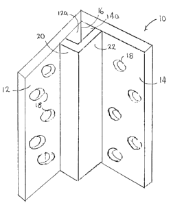
With reference to Figures 1 and 2, the bracket of the invention, generally 10,
includes
a pair of first plates 12, 14 which are interconnected along an edge 16 of
each such that the
angle between the two plates is a right angle.
A number of openings 18 are formed in the two plates for receipt of nails or
screws.
The nails or screws serve to attach the bracket to the frame of an opening.
A second plate 20 is connected to plate 12 and extends outwardly from it.
Plate 20
is connected to a second plate 22 which extends outwardly from the other plate
14. The inner
walls 20a, 22a, of the second plates together with the portions 12a, 14a of
the walls of the
first plates which face them define a space 24 for receipt of an upright rod.
With reference to Figure 3, a second plate 30 is continuous and curved and
extends
from one first plate 32 to the other first plate 34. The inside wall 30a of
the second plate
3
CA 02353337 2001-07-20
together with the walls of the first plate which face it define the space for
the upright rod.
With reference to Figures 4 and S, a barrier, generally 40, serves to prevent
unintended movement through opening 42. The barrier includes a pair of the
brackets 1 Oa,b
of the invention. The brackets are attached to frame 44 of the opening, but
they may also be
attached to joists 46, to other timber in the vicinity of the opening or to
whatever else is
convenient. In general the brackets should not be attached in such a way that
they will
protrude into the opening. The brackets will not then be an obstacle for
material that it is to
be passed through the opening when the barrier is removed.
Upright rods 50, 52 are received in the spaces of each bracket between their
first and
second plates. A number of L-shaped supports 54 are spaced vertically apart on
each upright
and vertically spaced horizontal rails 56, 58 rest on supports at the same
elevation. The rails
may be two-by-fours, as illustrated, or wooden or steel rods of sufficient
strength to prevent
a person from accidentally breaking through them.
The barrier may be removed from the opening simply by removing the horizontal
rails from the supports and the uprights are then raised to remove them from
the space in
each bracket that accommodates them.
It will be understood, of course, that modifications can be made in the
embodiments
of the bracket illustrated herein without departing from the scope and purview
of the
invention.
4