Sélection de la langue

Search

Sommaire du brevet 2359619 

Énoncé de désistement de responsabilité concernant l'information provenant de tiers

Une partie des informations de ce site Web a été fournie par des sources externes. Le gouvernement du Canada n'assume aucune responsabilité concernant la précision, l'actualité ou la fiabilité des informations fournies par les sources externes. Les utilisateurs qui désirent employer cette information devraient consulter directement la source des informations. Le contenu fourni par les sources externes n'est pas assujetti aux exigences sur les langues officielles, la protection des renseignements personnels et l'accessibilité.

Disponibilité de l'Abrégé et des Revendications

L'apparition de différences dans le texte et l'image des Revendications et de l'Abrégé dépend du moment auquel le document est publié. Les textes des Revendications et de l'Abrégé sont affichés :

  • lorsque la demande peut être examinée par le public;
  • lorsque le brevet est émis (délivrance).
(12) Brevet: (11) CA 2359619
(54) Titre français: RACCORD POUR TUYAUX A SPIRALE D'ACIER
(54) Titre anglais: COUPLING FOR CORRUGATED FLEXIBLE HOSE
Statut: Réputé périmé
Données bibliographiques
(51) Classification internationale des brevets (CIB):
  • F16L 25/00 (2006.01)
  • F16L 33/26 (2006.01)
(72) Inventeurs :
  • WEINHOLD, KARL (Allemagne)
(73) Titulaires :
  • WEINHOLD, KARL (Allemagne)
(71) Demandeurs :
  • WEINHOLD, KARL (Allemagne)
(74) Agent: KIRBY EADES GALE BAKER
(74) Co-agent:
(45) Délivré: 2009-02-10
(86) Date de dépôt PCT: 1999-12-29
(87) Mise à la disponibilité du public: 2000-08-24
Requête d'examen: 2004-09-21
Licence disponible: S.O.
(25) Langue des documents déposés: Anglais

Traité de coopération en matière de brevets (PCT): Oui
(86) Numéro de la demande PCT: PCT/EP1999/010444
(87) Numéro de publication internationale PCT: WO2000/049325
(85) Entrée nationale: 2001-08-03

(30) Données de priorité de la demande:
Numéro de la demande Pays / territoire Date
199 07 412.7 Allemagne 1999-02-20

Abrégés

Abrégé français

L'invention concerne un raccord pour tuyaux comportant une bride composée d'au moins deux coques partielles (1a, 1b) et entourant le tuyau, ainsi qu'un levier de serrage (3) articulé sur l'extrémité périphérique libre de l'une des coques partielles (1a, 1b) par l'intermédiaire d'un boulon (4). Pour créer une liaison de force entre le tuyau et un manchon (8) inséré dans le tuyau, le levier de serrage peut être relié à l'autre extrémité périphérique libre de la coque partielle correspondante (1a ou 1b) par l'intermédiaire d'un ressort de fermeture (6). La mâchoire de serrage (1) peut être fixée sur le manchon (8) en sens axial au moyen d'une collerette immobile axialement. L'invention vise à fournir un raccord pour tuyaux de structure simple, de production économique et pouvant servir de raccord rapide pour des tuyaux à spirale d'acier. A cet effet, le collier présente plusieurs coques partielles (1a, 1b) et est fabriqué d'une pièce en plastique sous forme de mâchoire de serrage (1). Les liaisons entre les coques partielles (1a, 1b) sont réalisées sous forme de charnières à film, le tuyau est un tuyau à spirale d'acier (9) et les coques partielles (1a, 1b) présentent à l'intérieur de la mâchoire de serrage (1) une rainure en spirale (10) servant à loger la spirale d'acier du tuyau (9) et enveloppent ainsi le tuyau à spirale d'acier (9) avec liaison de forme.


Abrégé anglais


The invention relates to a hose coupling comprising a clip
consisting of at least two semi-cylindrical cups (1a, 1b)
enclosing the hose and a clamping lever (3) which via a bolt (4)
is articulated on the free peripheral end of one of the semi-
cylindrical cups (1a, 1b). To create a force-fit connection
between the hose and a sleeve (8) inserted into same, the
clamping lever can be connected to the other free peripheral end
of the corresponding semi-cylindrical cup (1a or 1b) via a
closing spring (6). The clamping jaw (1) can be fixed on the
sleeve (8) in an axial direction by means of a flange which is
mounted on said sleeve (8) in such a way that it cannot be
axially displaced. The aim of the invention is to provide such a
hose coupling which has a simple structure, is economical to
produce and can be used as quick-release coupling for corrugated
flexible hose. To this end, the clip comprises several semi-
cylindrical cups (1a, 1b) and is configured as a single-piece
clamping jaw (1) made of a plastic material. The connection(s)
between the semi-cylindrical cups (1a, 1b) are configured as
integral hinge(s), the hose is a corrugated flexible hose (9)
and the semi-cylindrical cups (1a, 1b) on the inside of the
clamping jaw (1) present a helical groove (10) which receives
the corrugations of the corrugated flexible hose (9) and in this
way hold said hose (9) in a form-fit connection.

Revendications

Note : Les revendications sont présentées dans la langue officielle dans laquelle elles ont été soumises.


-8-

CLAIMS


1. A hose coupling comprising a clip consisting of at
least two semi-cylindrical cups enclosing a hose,
and a clamping lever which via a bolt is
articulated on the free peripheral end of one of
the semi-cylindrical cups; to create a non-
positive connection between the hose and a sleeve
inserted in said hose, the clamping lever
connectable to the other free peripheral end of
the corresponding semi-cylindrical cup via a
closing spring, with a clamping jaw being fixable
on the sleeve in axial direction by means of a
flange which is arranged on said sleeve in such a
way that it cannot be axially displaced,
characterized in that the clip comprises one or
more semi-cylindrical cups and is configured as a
single-piece clamping jaw made of a plastic
material, with the connection(s) between the semi-
cylindrical cups being configured as an integral
hinge/integral hinges, that the hose is a
corrugated flexible hose and that the semi-
cylindrical cups on the inside of the clamping jaw
comprise a helical groove which receives the
corrugations of the corrugated flexible hose and
in this way hold said corrugated flexible hose in
a form-fit connection.


-9-

2. The coupling according to claim 1, characterized
in that the semi-cylindrical cups in the interior
of the clamping jaw comprise at least one web-like
elevation extending parallel to a spiral-shaped
groove.

3. The coupling according to claim 1 or 2,
characterized in that the flange on the sleeve is
an annular collar and that the semi-cylindrical
cups in the interior of the clamping jaw comprise
an annular groove for receiving the annular
collar.

4. The coupling according to claim 1 or 2,
characterized in that the sleeve, at its free end
pointing away from the hose, comprises a flange
which is movably connected to the clamping jaw.

5. The coupling according to claim 4, characterized
in that the flange comprises a web which comprises
an elongated hole through which a bolt reaches,
with said bolt interconnecting the clamping lever
and the clamping jaw.


-10-

6. The coupling according to claim 4 or 5,
characterized in that the flange is arranged on
the sleeve so as to be rotatable but so that it
cannot be axially displaced.

7. The coupling according to any one of claims 1 to
6, characterized in that the sleeve comprises an
annular groove in its region encompassed by the
hose end, with a seal being inserted in said

annular groove.

8. The coupling according to claim 7, characterized
in that the seal is a toroidal sealing ring.

9. The coupling according to any one of claims 1 to
8, characterized in that the clamping lever is
made of stainless steel.

10. The coupling according to any one of claims 1 to
9, with the closing spring being hinged to a pin
arranged parallel to the bolt, characterized in
that the bolt, the pin or the closing spring or
both are made of stainless steel.

Description

Note : Les descriptions sont présentées dans la langue officielle dans laquelle elles ont été soumises.


CA 02359619 2007-11-23
jr -1-

COUPLING FOR CORRUGATED FLEXIBLE HOSE

The invention relates to a hose coupling comprising a
clip consisting of at least two semi-cylindrical cups
enclosing the hose, and a clamping lever which via a bolt
is articulated on the free peripheral end of one of the
semi-cylindrical cups. To create a non-positive connection
between the hose and a sleeve inserted into said hose,
the clamping lever can be connected to the other free
peripheral end of the corresponding semi-cylindrical cup
via a closing spring, with the clamping jaw being fixable
on the sleeve in axial direction by means of a flange
which is arranged on said sleeve in such a way that it
cannot be axially displaced.

Many different types of couplings for hoses are known.
Thus a generic hose coupling is known from DE 28 49 880
Al originating from this applicant.

Furthermore, DE 36 01 093 C2 describes such a hose
coupling in which two semi-cylindrical cups are hingeably
joined. However this known coupling can only be used for
conventional hoses, not for corrugated flexible hoses.
Corrugated flexible hoses are thin-walled plastic hoses
with corrugations made of steel that have been
vulcanised-in. There are no quick-release couplings
available on the market for such corrugated flexible
hoses which are increasingly used in industry. Thus the


CA 02359619 2007-11-23
-2-

hoses always have to be fixed with relatively expensive screw-
connections.

It is thus the object of the invention to provide an armature
which is suitable to be used as a quick-release coupling for
corrugated flexible hoses. Furthermore it is desirable that
the coupling is of simple construction and is economical to
produce.

This object is met by a hose coupling comprising a clip
consisting of at least two semi-cylindrical cups enclosing a
hose, and a clamping lever which via a bolt is articulated on
the free peripheral end of one of the semi-cylindrical cups;
to create a non-positive connection between the hose and a
sleeve inserted in said hose, the clamping lever connectable
to the other free peripheral end of the corresponding semi-
cylindrical cup via a closing spring, with a clamping jaw
being fixable on the sleeve in axial direction by means of a
flange which is arranged on said sleeve in such a way that it
cannot be axially displaced, characterized in that the clip
comprises one or more semi-cylindrical cups and is configured
as a single-piece clamping jaw made of a plastic material,
with the connection(s) between the semi-cylindrical cups being
configured as an integral hinge/integral hinges, that the hose
is a corrugated flexible hose and that the semi-cylindrical
cups on the inside of the clamping jaw comprise a helical
groove which receives the corrugations of the corrugated
flexible hose and in this way hold said corrugated flexible
hose in a form-fit connection.


CA 02359619 2007-11-23
-2a-

According to the invention, a reliable frictional connection
between the clamping jaw and the hose is achieved and an
armature is provided which can be used as a coupling for
extending and/or connecting corrugated flexible hoses. This
further enhances the attractiveness of using corrugated
flexible hoses. The coupling according to the invention is of
simple construction and is economical to produce.

To improve the form fit between the hose and the sleeve, a
further teaching of the invention provides for the


CA 02359619 2001-08-03
- 3 -

semi-cylindrical cups in the interior of the clamping jaw
to comprise at least one web-like elevation extending
parallel to the spiral-shaped groove. This embodiment
reliably ensures that the hose end located in the sleeve
cannot "unscrew" from the clamping jaw.

A further teaching of the invention provides for the
flange on the sleeve, which flange absorbs axial tension,
to be an annular collar and that the semi-cylindrical
cups in the interior of the clamping jaw comprise an
annular groove for receiving the annular collar.

In an alternative embodiment of the invention, the
sleeve, at its free end pointing away from the hose,
comprises a flange which is movably connected to the
clamping jaw. In this embodiment the flange preferably
comprises a web which comprises an elongated hole through
which a bolt reaches, said bolt interconnecting the
clamping lever and the clamping jaw. Thus, by connecting
the clamping jaw with the sleeve, this embodiment
provides a captive coupling.

In a further embodiment of the invention, the coupling
according to the above embodiment provides for a flange
which is arranged on the sleeve so as to be rotatable but
so that it cannot be axially displaced. This rotatability
provides the advantage that the sleeve can rotate in the
clamping jaw so that prior to closing the coupling, the
corrugations of the hose can be aligned in a simple way
to the shape of the clamping jaw, without the hose in the
sleeve having to be rotated accordingly.

To further improve the seal between hose and sleeve, it
is provided for the sleeve to comprise an annular groove
TH/cj 990072AU


CA 02359619 2001-08-03
- 4 -

in its region encompassed by the hose end, with a seal
being inserted in said annular groove, said seal
preferably being an o-ring/toroidal sealing ring.
Finally, in order to achieve a long service life of the
coupling according to the invention, it is provided for
the clamping lever to be made of stainless steel. If the
closing spring is hinged to a pin arranged parallel to
the bolt, preferably the bolt, the pin and/or the closing
spring are made of stainless steel. In this way the
coupling according to the invention can also be
permanently used in a corrosive environment.

Below, the invention is shown in detail by means of a
drawing showing only preferred embodiments, as follows:
Fig. lA shows a top view of a first embodiment of the
coupling according to the invention, without
hose, and with the sleeve in its closed
position;

Fig. 1B shows the coupling according to Fig. 1A in its
open position;

Fig. 2 shows a lateral view, partly opened up, of the
coupling with the sleeve in place;

Fig. 3A shows a longitudinal view of the coupling
according to Fig. lA, with sleeve and (partly
opened up) hose;

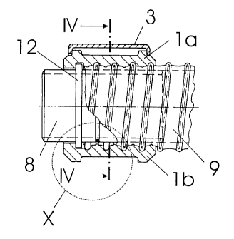
Fig. 3B is an enlarged view of the circle "X" in Fig.
3A;

TH/Cj 990072AU


CA 02359619 2001-08-03
- 5 -

Fig. 4 shows a cross section of the coupling according
to Fig. 1A, along the line IV-IV in Fig. 3A;
Fig. 5A shows a top view of a further embodiment of the
coupling according to the invention, without
hose, in its closed position;

Fig. 5B shows the coupling according to Fig. 5A in its
open position;

Fig. 6 shows a lateral view, partly opened up, of the
coupling from Fig. 5A;

Fig. 7 shows a longitudinal section of the coupling
according to Fig. 5A with hose (partly opened
up);

Fig. 8 shows a cross section along line VIII-VIII of
Fig. 3A, of the coupling according to Fig. 1A.
Figs. 1 to 4 show a first preferred embodiment of the
coupling for corrugated flexible hoses, according to the
invention. In the embodiment shown which insofar is the
preferred embodiment, a clamping jaw 1 comprises two
semi-cylindrical cups la and lb which are made in one
piece from plastic and which comprise a hinging point
which is an integral hinge 2. On the free peripheral end
of the semi-cylindrical cup la, the clamping jaw 1
comprises a clamping lever 3 which by means of a bolt 4
is hingeably connected to the semi-cylindrical cup la as
is shown particularly clearly in Fig. 1B. Furthermore,
the clamping lever 3 comprises a pin 5 which is used to
hold in place the end of a closing spring 6. The free end
of the closing spring 6 is shaped such that it interacts

TH/cj 990072AU


CA 02359619 2001-08-03
- 6 -

with a lug 7 arranged on the semi-cylindrical cup lb so
as to produce the necessary closing pressure, as is shown
particularly clearly in Fig. 4.

For safe connection between clamping jaw 1 and sleeve 8
onto which the end of a corrugated flexible hose 9 has
been placed, in the embodiment shown which insofar is the
preferred embodiment, a helical groove 10 for receiving
the corrugations of the hose 9 is provided in the
interior of the clamping jaw 1. This is shown
particularly clearly in Figs. 3A and 3B. To increase
friction between sleeve 8 and hose 9 there is a web-like
elevation 11 extending parallel to the helical groove 10.
This is shown in Figs. 3A and 3B. This embodiment
reliably precludes any "unscrewing" of the end of the
corrugated flexible hose 9 from the clamping jaw 1, when
said corrugated flexible hose 9 is subject to torsion.

So as to absorb the necessary axial tension, the sleeve 8
too has to establish a form-fit connection with the
clamping jaw 1. To this effect, the sleeve comprises a
flange which is arranged in such a way that it cannot be
axially displaced. Preferably, said flange is an annular
collar 12 which is received by an annular groove 13 of
the clamping jaw 1. This too is shown particularly
clearly in Figs. 3A and 3B.

So as to provide a reliable seal between the sleeve 8 and
the hose 9, the sleeve 8 comprises an annular groove 18
with an inserted seal which in the embodiment shown is a
toroidal sealing ring 19. It is clear that the diameter
of the toroidal sealing ring 19 matches the annular
groove 18 so that the toroidal sealing ring 19 protrudes
beyond the external diameter of the sleeve 8.

TH/Cj 990072AU


CA 02359619 2001-08-03
- 7 -

Figs. 5 to 8 show a further embodiment of the coupling
according to the invention, in which embodiment the
clamping jaw 1 and the sleeve 8 are hingeably
interconnected so that this further embodiment of the
coupling according to the invention can be used as a
captive coupling. For the sake of simplicity, the same
reference characters have been used for the same parts.
In contrast to the first embodiment, in this embodiment
the sleeve 8 comprises a flange 14 which is not arranged
within the clamping jaw 1 but instead on the free end of
the sleeve 8. This is shown particularly clearly in Figs.
6 and 7. This flange 14 rests against a shoulder (no
reference character) located at the free end of the
sleeve 8. Said flange 14 is secured by a retaining ring
15 so that the flange 14 is arranged on the sleeve 8 so
that it cannot be axially displaced but can rotate
freely.

In this embodiment, the flange 14 comprises a web 16
which comprises an elongated hole 17 through which a bolt
4, which connects the clamping lever 3 to the clamping
jaw 1, reaches. As is shown in Fig. 5B, the elongated
hole is used to swivel out the sleeve 8 from the semi-
cylindrical cup la after the semi-cylindrical cup lb has
been swung open. Depending on the arrangement of the
clamping jaw 1 and the flange 14, it may be necessary to
define the spacing of the two parts in the region of the
bolt 4 by using a spacer 20, as is shown in Fig. 6.

TH/Cj 990072AU

Dessin représentatif
Une figure unique qui représente un dessin illustrant l'invention.
États administratifs

Pour une meilleure compréhension de l'état de la demande ou brevet qui figure sur cette page, la rubrique Mise en garde , et les descriptions de Brevet , États administratifs , Taxes périodiques et Historique des paiements devraient être consultées.

États administratifs

Titre Date
Date de délivrance prévu 2009-02-10
(86) Date de dépôt PCT 1999-12-29
(87) Date de publication PCT 2000-08-24
(85) Entrée nationale 2001-08-03
Requête d'examen 2004-09-21
(45) Délivré 2009-02-10
Réputé périmé 2013-12-31

Historique d'abandonnement

Il n'y a pas d'historique d'abandonnement

Historique des paiements

Type de taxes Anniversaire Échéance Montant payé Date payée
Le dépôt d'une demande de brevet 300,00 $ 2001-08-03
Taxe de maintien en état - Demande - nouvelle loi 2 2001-12-31 100,00 $ 2001-11-14
Taxe de maintien en état - Demande - nouvelle loi 3 2002-12-30 100,00 $ 2002-11-21
Taxe de maintien en état - Demande - nouvelle loi 4 2003-12-29 100,00 $ 2003-11-21
Requête d'examen 800,00 $ 2004-09-21
Taxe de maintien en état - Demande - nouvelle loi 5 2004-12-29 200,00 $ 2004-11-12
Taxe de maintien en état - Demande - nouvelle loi 6 2005-12-29 200,00 $ 2005-12-13
Taxe de maintien en état - Demande - nouvelle loi 7 2006-12-29 200,00 $ 2006-11-09
Taxe de maintien en état - Demande - nouvelle loi 8 2007-12-31 200,00 $ 2007-10-31
Taxe de maintien en état - Demande - nouvelle loi 9 2008-12-29 200,00 $ 2008-10-16
Taxe finale 300,00 $ 2008-11-28
Taxe de maintien en état - brevet - nouvelle loi 10 2009-12-29 250,00 $ 2009-12-04
Taxe de maintien en état - brevet - nouvelle loi 11 2010-12-29 450,00 $ 2011-11-16
Taxe de maintien en état - brevet - nouvelle loi 12 2011-12-29 250,00 $ 2011-11-16
Titulaires au dossier

Les titulaires actuels et antérieures au dossier sont affichés en ordre alphabétique.

Titulaires actuels au dossier
WEINHOLD, KARL
Titulaires antérieures au dossier
S.O.
Les propriétaires antérieurs qui ne figurent pas dans la liste des « Propriétaires au dossier » apparaîtront dans d'autres documents au dossier.
Documents

Pour visionner les fichiers sélectionnés, entrer le code reCAPTCHA :


Pour visualiser une image, cliquer sur un lien dans la colonne description du document. Pour télécharger l'image (les images), cliquer l'une ou plusieurs cases à cocher dans la première colonne et ensuite cliquer sur le bouton "Télécharger sélection en format PDF (archive Zip)" ou le bouton "Télécharger sélection (en un fichier PDF fusionné)".

Liste des documents de brevet publiés et non publiés sur la BDBC .

Si vous avez des difficultés à accéder au contenu, veuillez communiquer avec le Centre de services à la clientèle au 1-866-997-1936, ou envoyer un courriel au Centre de service à la clientèle de l'OPIC.


Description du
Document 
Date
(yyyy-mm-dd) 
Nombre de pages   Taille de l'image (Ko) 
Revendications 2001-08-03 3 89
Dessins 2001-08-03 4 101
Page couverture 2001-11-23 1 50
Abrégé 2001-08-03 1 38
Description 2001-08-03 7 282
Dessins représentatifs 2001-11-22 1 9
Abrégé 2008-12-05 1 38
Description 2004-09-21 7 273
Revendications 2004-09-21 3 84
Revendications 2007-11-23 3 75
Description 2007-11-23 8 290
Dessins représentatifs 2009-01-21 1 10
Page couverture 2009-01-21 2 56
PCT 2001-08-03 10 387
Cession 2001-08-03 4 104
Correspondance 2001-11-08 1 24
Correspondance 2001-12-04 1 12
PCT 2001-08-06 6 164
Taxes 2001-11-14 1 41
Poursuite-Amendment 2007-05-24 2 74
Poursuite-Amendment 2004-09-21 6 167
Poursuite-Amendment 2007-11-23 9 263
Correspondance 2008-11-28 1 40
Taxes 2011-11-16 1 163