Note : Les descriptions sont présentées dans la langue officielle dans laquelle elles ont été soumises.
CA 02362386 2007-01-16
-1-
DEVICE FOR DISCHARGING FLOWABLE MATERIALS
BACKGROUND
Technical Field
The invention is directed to a motor driven dispensing device for dispensing
flowable substances from a container.
Description of the Related Prior Art
A device for dispensing flowable substances is known from European Patent
Application 0 492 413 Al published July 1, 1992. There is provided a shell-
shaped
receptacle for receiving two cartridges in parallel, each cartridge having, at
its rear end, a
dispensing piston and, at its front end, an opening to be coupled to a rear
entry opening of
a mixer provided on the device. During dispensing, both pistons are
synchronously
advanced by an electrical motor which also drives a rotor within the mixer.
The advancing speed of the pistons and, possibly, also the driving speed of
the
mixer rotor can depend upon the properties of the substances containecl in the
cartridges,
such as viscosity or sensitivity to mechanical forces. The proper dispensing
parameters
are to be selected by the operator. Setting unsuitable parameters may lead to
undesired
changes of the substance being dispensed or damages to the device.
Some substances have properties that change over time and are therefore to be
used
prior to an expiry date determined by the producer. This is particularly true
with
components which react with each other and are mixed together for producing a
ready-to-
use substance. If the operator fails to pay attention to the expiry date, the
substance
dispensed from the device may be unusable or at least deteriorated in its
properties.
Finally, it is essential for each cartridge to be properly inserted into the
receptacle
of the device. If this is not done, entry of the piston into the cartridge
and/or engagement
of the mixer shaft in the mixer is not properly ensured, which may cause
damage to the
device, lead to unmixed substances being dispensed, or result in leakage.
Again, one
relies on the operator to insert the cartridges properly.
German Patent Application 39 19 105 Al, published August 20, 1992, discloses a
gluing machine in which cartridges are filled with adhesive components in a
predetermined mixing ratio. A visible marking tells the operator whether the
machine has
been properly filled in accordance with the mixing ratio. There is also
mention of a
"pneumatic" encoding and inhibition of the gluing machine if wrong cartridges
are
inserted.
CA 02362386 2007-01-16
-2-
SUMMARY OF THE INVENTION
It is the object of the invention to prevent such a dispensing device from
being
improperly handled, specifically from having a container improperly inserted
or an
unsuited container being inserted, possibly also an unsuited mixer being used.
The present invention provides a solution to this object. According to an
embodiment of the present invention, a marking provided on the container and
its
detection by means provided in the device ensure that the emptying mechanism
of the
device functions only if the marking has been recognised as admissible, and
possibly
operates in response to the contents of the marking. The marking may contain
information
1o concerning the properties of the container content, its dm ability, the
producer, and other
data. Since the marking and the detecting means must be related to each other,
it becomes
possible to ensure that the marking is recognised as valid only if the
container is in a
predetermined position within the receptacle of the device.
It is of particular advantage to use the marking foi- establishing not only
the proper
position of the container but also the proper operation of the device,
according to two
embodiments of the present invention.
Another embodinient of the present invention is specifically related to the
detection
of the internal pressure of the container which, under certain conditions, may
become
excessive during dispensing. To this end, it is specifically a deformation of
the container
cap that is detected, which deformation may occur if it is attempted to
dispense improper
or too old and taut pastes whereby a certain maximum dispensing force is
exceeded. It
thus becomes possible to avoid damage to the dispensing device, contamination
of the
device due to breakage of a container, or other i-isks. There is thus not only
detection as to
whether a container suited for the device has been properly inserted; overload
conditions
during dispensing are also prevented. This avoids the need for an expensive
overload
clutch, as is provided with some prior-art devices.
Another embodiment of the present invention is of advantage in that it ensures
the
use of a proper mixture in a mixing and dispensing device for mixtures of two
or more
components.
Yet another embodiment of the present invention is advantageous in that
certain
information contained in the marking, such as the expiry date, are immediately
recognisable to the user.
CA 02362386 2007-01-16
- 2a -
In accordance with one aspect of the present invention there is provided a
mixing
and discharging apparatus for two-component and multi-component materials,
with a
housing for the reception of containers which contain the components at least
one of
which is provided with a marking, having a device for emptying the containers
by means
of synchronously advanceable pistons, the housing of the apparatus having a
device for
detecting the marking and for controlling the speed of advance of the pistons
and/or the
rotational speed of the mixer rotor with a dynamic mixer, connectable to the
mixing and
discharging apparatus or to the containers, as a function of information
contained in the
marking and relating to the component stored in the container.
In accordance with another aspect of the present invention there is provided a
use
of a container in a mixing and discharging apparatus for two-component or
multi-
component materials, the container having a marking for controlling the speed
of advance
of discharging pistons of this apparatus and/or the rotational speed of the
mixer rotor of a
dynamic mixer connectable to the apparatus or to the container, and the
apparatus having a
housing for receiving the container and a device detecting the marking
BRIEF DESCRIPTION OF THE DRAWINGS
Preferred embodiments of the invention will be desci-ibed below with reference
to
the drawings, in which
Figure 1 is a longitudinal section through the front part of a dispensing
device,
CA 02362386 2007-01-16
-3--
Figure 2 is a perspective view of a cap which constitutes the front part of a
con-
tainer,
Figure 3 is a peispective view similar to Figure 2 showing the container cap
of a
further embodiment,
Figure 4 illustrates part of a device adapted to the arrangement of Figure 3,
Figures 5a to 5c are schematic views of part of the dispensing device with
means
for detecting the container marking in accordance with a further em-
bodiment, and
Figures 6a to 6c are representations similar to Figures 5a to 5c, illustrating
yet an-
other embodiment.
DESCRIPTION OF THE PREFERRED EMBODIMENTS
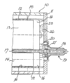
The dispensing device shown in part in Figure 1 includes a housing 10 having
an end wall
11 and a receptacle 12 for receiving two substantially cylindrical containers
13, 14 in
parallel.
In the present case, each of the containers 13, 14 is constituted by a film
tube 15
the front end of which is glued into a rigid cap 16. Figure 1 shows vai-ious
details only of
the container 13, whereas the container 14 is shown only schematically. Figure
2 is a
perspective view of the cap 16.
The film tubes 15 of the two containers 13, 14, are emptied by pistons (not
shown)
which engage their rear ends and which are synchronously advances by an
electrical motor
(not shown). The motor also rotates a shaft 17 the front end of which is
coupled to a i-otor
18 of a dynamic mixer 19 connected to either the container caps 16 or the
housing end
wall 11. Either cap 16 has an outlet pipe 20 which leads into a corresponding
inlet pipe 21
provided at the rear end of the mixer 19.
A transponder 25 is disposed at the front end of the cap 16, in which data are
stored
that are related to the container 13, its contents, the expiry date of the
contents and/or the
producer. A sensor 26 cooperating with the transponder 25 is disposed at a
position of the
housing end wall 11 exactly opposite the transponder 25. When the container 13
is in its
prescribed position in which the transponder 25 is sufficiently close to the
sensor 26, the
data stored in the transponder 25 are received by the sensor 26 which enables
the actuation
of the dispensing device if these data correspond to those stored in a control
of the device.
The actual operation for driving the dispensing; pistons and the mixer shaft
17 is initiated
by a switch (not shown).
Where the data transmitted from the transponder 25 to the sensor 26 contain
infor-
mation on the substance in the container 13, the advancing speed of the
dispensing pistons
and/or the rotational speed of the mixer rotor 18 may be controlled
correspondingly.
CA 02362386 2001-06-21
-4-
Additional means (not shown) may be provided to provide an indication of the
data
transmitted from the transponder 25, such as the expiry date. The indicating
means may be
in the form of a display on the device or on a separate screen.
The second container 14 shown in Figure 1 may also be provided with a transpon-
der, just as the container 13, the transponder cooperating with a sensor
correspondingly
positioned on the end wall 11 of the device housing 10. In this case, it may
be ensured that
both containers contain suitable components for producing the desired mixture.
In an alternative embodiment, only one of the two containers 13, 14 of the
dispens-
ing device shown in Figure 1 may be provided with a transponder 25, and the
device may
l0 be provided with a single sensor 26. Further, the transponder 25 and the
sensor 26 may be
located at positions other than those shown in the drawings.
The invention is not restricted to devices for producing substances from two
or
more components. A transponder 25 provided on a container 13, which holds a
substance
to be dispensed, and cooperating with a sensor 26 on the device is useful also
in a pure dis-
pensing device. In this case, the data stored in the transponder 25 may be
used to control
the dispensing speed and/or prevent the use of a substance that has expired.
Instead of the transponder 25 assumed in Figures 1 and 2, the marking of the
con-
tainer may be contained in a magnetic code or an optically readable bar code
provided on
the end wall of the cap 16, and the respective code may be sensed by a
corresponding mag-
netic or optical code reader located at a position of the end wall 11 of the
housing 10 corre-
sponding to the sensor 26 in Figure 1.
In yet another embodiment (not shown), the marking of the container or
container
contents may be provided in an electronic circuit chip again located at the
position of the
transponder 25 in Figure 1 and cooperating with a corresponding sensor 26
provided on the
end wall 11 of the housing 10. In this case, the sensor may include contact
elements for the
circuit chip and a processor connected to such contact elements.
In the second embodiment of the invention shown in Figures 3 and 4, recesses
or
holes 31 are provided on a rib 30 which projects in the forward direction from
the cap 16.
When the container 13 is completely inserted in the device, these recesses or
holes 31 may
be engaged by actuator pins 32 of microswitches 33 disposed on a web 34 that
extends
parallel to the rib 30 and projects rearward from the housing end wall 11.
In the embodiment shown, the rib 30 is provided with four holes 31 which
cooper-
ate with the actuator pins 32 of a total of four microswitches 33. In this
case, when the
container 13 is inserted from the above in Figure 4, none of the microswitches
33 is actu-
ated. If only some of the holes 31 are provided in the rib 30, only those
microswitches 33
CA 02362386 2001-06-21
-5-
are actuated that have actuator pins 32 for which no hole is provided. Thus,
different in-
formation is transmitted depending on the number of holes 31 provided in the
rib 30.
Instead of the holes 31 provided in the rib 30 in the cap 16, as shown in
Figures 3
and 4, other surface formations similar to a key bit may be provided in which
data related
to the container 13 or the container contents are coded. In this case, the
housing 10 has cor-
responding spring elements to sense such surface formations and detect
information corre-
sponding to the configuration thereof.
In addition to, or instead of, the marking provided on the container, a
marking (not
shown) may be provided on the mixer which cooperates with the same or a
separate
evaluation unit provided on the device housing 10 in order to ensure that the
appropriate
mixer 19 is used in relation to the device and/or the substance to be
dispensed. In this case,
the device control is so arranged that it enables the operation of the device
only if both
markings coincide with the data provided in the control.
Figures 5a to 5c are schematic representations showing only a part of the
peripheral
wall 40 and a part of the end wall 41 of the container receptacle of a
dispensing device.
This device largely corresponds to that shown in Figure 1 but differs
therefrom in that a
sensor 42 in the form of a pivotal rod extends from the peripheral wall 40
into the space re-
ceiving the container 13 (Figure 5b).
In Figure 5a, the sensor 42 is in a rest position biased to the right, which
the sensor
assumes when no container is placed in the dispensing device.
In the representation of Figure 5b, a container 13 is in its normal operating
position.
The container 13 has a projection 43 at the end surface of its cap 16'. The
projection 43 de-
flects the sensor 42 from the position shown in Figure 5a along the piston
advancing direc-
tion to the normal operating position. In this position of the sensor 42, the
dispensing de-
vice is ready for operation.
If the container 13 is not properly inserted into the device or if it is a
container
which is not suited for use with the device and may cause malfunction, the
sensor 42 is not
deflected from its rest position, thereby disabling the dispensing operation.
Figure 5c shows a case in which the cap 16' of the container 13 has become de-
formed due to excessive pressure so that the projection 43 deflects the sensor
42 beyond its
normal operating position to an abnormal position. The dispensing process is
interrupted in
this position of the sensor 42.
Such a deformation of the housing cap 16' may occur if it is attempted to
dispense
improper or too old, thus taut pastes, so that a certain maximum dispensing
pressure F is
exceeded. Damage to the dispensing device, contamination of the device due to
breakage
of a container and other hazards are thus reliably prevented.
CA 02362386 2001-06-21
-6-
The abnormal position of the sensor 42 shown in Figure 5c may be caused also
by
the use of an improper container which has an excessive projection at the end
wall of the
cap 16' in the area of the sensor 42.
The embodiment shown schematically in Figures 6a to 6c differs from that of
Fig-
ures 5a to 5c in that the projection 43 at the cap 16" of the container 13 is
replaced by a re-
flecting mark 44 which is sensed by an light barrier 47 comprising a light
emitter 45 and a
light receiver 46. In the rest position shown in Figure 6a, in which no
container has been
inserted, the light beam emitted by the light emitter 45 is insufficiently
reflected.
In the normal operating condition shown in Figure 6b, the light beam is
reflected by
the reflecting mark 44 onto the light receiver 46, the output signal of which
is supplied to
an evaluation circuit (not shown) to enable the operation of the dispensing
device.
If the container cap 16" is deformed due to overload, the light beam reflected
by the
reflecting mark 441eaves the light receiver 46 which then generates no output
signal. Such
an abnormal condition is detected by the evaluation circuit which interrupts
the dispensing
process.
The embodiments of Figures 5a to 5c and 6a to 6c thus permit not only the
detec-
tion as to whether a container suited for use in the device has been properly
inserted, but
also prevent overload conditions during dispensing. In some prior art devices,
such an
overload condition is prevented by a separate, expensive overload clutch in
the drive
mechanism, which the invention renders superfluous.