Sélection de la langue

Search

Sommaire du brevet 2364623 

Énoncé de désistement de responsabilité concernant l'information provenant de tiers

Une partie des informations de ce site Web a été fournie par des sources externes. Le gouvernement du Canada n'assume aucune responsabilité concernant la précision, l'actualité ou la fiabilité des informations fournies par les sources externes. Les utilisateurs qui désirent employer cette information devraient consulter directement la source des informations. Le contenu fourni par les sources externes n'est pas assujetti aux exigences sur les langues officielles, la protection des renseignements personnels et l'accessibilité.

Disponibilité de l'Abrégé et des Revendications

L'apparition de différences dans le texte et l'image des Revendications et de l'Abrégé dépend du moment auquel le document est publié. Les textes des Revendications et de l'Abrégé sont affichés :

  • lorsque la demande peut être examinée par le public;
  • lorsque le brevet est émis (délivrance).
(12) Demande de brevet: (11) CA 2364623
(54) Titre français: ENSEMBLE REVETEMENT
(54) Titre anglais: COVER ASSEMBLY
Statut: Morte
Données bibliographiques
(51) Classification internationale des brevets (CIB):
  • A63C 19/12 (2006.01)
(72) Inventeurs :
  • ELSE, ROBERT ARTHUR (Royaume-Uni)
(73) Titulaires :
  • TERRAPLAS PLC (Royaume-Uni)
(71) Demandeurs :
  • TERRAPLAS PLC (Royaume-Uni)
(74) Agent: RICHES, MCKENZIE & HERBERT LLP
(74) Co-agent:
(45) Délivré:
(86) Date de dépôt PCT: 2000-03-30
(87) Mise à la disponibilité du public: 2000-10-12
Licence disponible: S.O.
(25) Langue des documents déposés: Anglais

Traité de coopération en matière de brevets (PCT): Oui
(86) Numéro de la demande PCT: PCT/GB2000/001227
(87) Numéro de publication internationale PCT: WO2000/059589
(85) Entrée nationale: 2001-08-21

(30) Données de priorité de la demande:
Numéro de la demande Pays / territoire Date
9907607.7 Royaume-Uni 1999-04-06

Abrégés

Abrégé français

L'invention concerne un ensemble revêtement destiné à couvrir temporairement certaines surfaces, par exemple les patinoires, afin de servir de support à des personnes ou à des articles. L'ensemble comprend un certain nombre de composants (10) qui s'emboîtent dans d'autres composants adjacents semblables (10) sur la surface à couvrir. Les composants possèdent des parties supérieures et inférieures (12, 16) avec une séparation (20) entre lesdites parties assurant l'isolation par rapport à la surface sous-jacente. Les composants adjacents (10) sont fixés les uns aux autres par des organes de verrouillage (22) situés sur les deux côtés adjacents de chaque composant (10) et s'emboîtent de manière sélective dans les rainures (32) des composants adjacents (10).


Abrégé anglais


A cover assembly for temporarily covering areas such as an ice rink, to
support people or other items thereon. The assembly comprises a number of
components (10) which can be engaged with other such components (10) placed
adjacent thereto on the surface to be covered. The components include upper
and lower parts (12, 16) with a gap (20) being provided between such parts to
provide insulation from the underlying area. Adjacent components (10) are
retained together by locking means (22) which are provided on two adjacent
sides of each component (10), and are selectively engageable in recesses (32)
on adjacent components (10).

Revendications

Note : Les revendications sont présentées dans la langue officielle dans laquelle elles ont été soumises.


6


CLAIMS:

1. A cover assembly comprising a plurality of components (10) engageable
adjacent each other to cover the ground or another surface, each component
(10) comprising an upper (12) and lower part (16), each component (10) being
arranged such that the upper part (12) defines an at least generally planar
upper surface (14) upon which a person can be supported, the lower part (16)
being engageable with the ground or other surface, with a gap (20) being
provided between the lower and upper parts (16, 12) to provide insulation and
such that the upper part (12) is spaced from the ground or other surface,
characterised in that overlapping means (32) are provided on at least some of
the sides of the component (10) to cover any gap between adjacent components
(10).
2. A cover assembly according to claim 1, characterised in that a plurality
of spaced formations are provided on one of the upper or lower parts (12, 16)
and supportingly engageable with the other of said parts to space said parts
(12,
16) apart.
3. A cover assembly according to claim 2, characterised in that the
formations are provided is a regular pattern.
4. A cover assembly according to claims 2 ar 3, characterised in that the
formations are substantially frusto conical.
5. A cover assembly according to any of claims 2 to 4, characterised in that
the formations (18) are provided on the lower part (16).
6. A cover assembly according to any of the preceding claims, characterised
in that the lower part (16) is at least generally planar.
7. A cover assembly according to claim 6 when dependent on claim 5,
characterised is that the lower part (16) is formed from a single sheet of


7


material with the formations (18) being provided by shaping of the sheet.
8. A cover assembly according to any of the preceding claims,
characterised in that the gap (20) provided between the lower and upper parts
(16, 12) is filled with insulating means.
9. A cover assembly according to claim 8, characterised is that the
insulating means is a foamed material and desirably polyurethane foam.
10. A cover assembly according to any of claims 1 to 7, characterised in that
the gap is filled with air.
11. A cover assembly according to any of the preceding claims, characterised
in that one or more openings are provided extending into the gap (20) to
permit
venting thereof.
12. A cover assembly according to any of the preceding claims, characterised
in that the support surface (14) of the upper part (12) is contoured.
13. A cover assembly according to claim 12, characterised is that the support
surface (14) is contoured to aid the grip of persons walking thereon.
14. A cover assembly according to claims 12 or 13, characterised in that
formations are provided on the support surface (14) to aid the grip of persons
walking thereon.
15. A cover assembly according to any of the preceding claims, characterised
in that each component (10) is of substantially rectangular shape.
16. A cover assembly according to clam 15, characterised in that each
component (10) is substantially square.
17. A cover assembly according to any of the preceding claims, characterised


8


in that locking means (22) are provided for selectively retaining together
adjacent components (10).
18. A cover assembly according to claim 17, characterised in that the locking
means (22) are provided on some of the sides of the component (10).
19. A cover assembly according to claim 18, characterised in that the locking
means (22) are provided on two of the sides of the component (10).
20. A cover assembly according to claims 18 or 19, characterised in that a
plurality of locking means (22) are provided along each said side.
21. A cover assembly according to any of claims 17 to 20, characterised in
that the locking means (22) comprise a locking member (26) mounted on the
component (10) to be movable between a locked position extending generally
laterally from the component (10) so as to be engageable with an adjacent
component (10), and as unlocked position contained substantially wholly
within the component (10).
22. A cover assembly according to claim 21, characterised in that the locking
member (26) is pivotally mounted on the component (10).
23. A cover assembly according to claims 21 or 22, characterised in that the
locking member (26) comprises a curved engagement part (28).
24. A cover assembly according to claim 23, characterised in that the
engagement part (28) may be substantially arcuate.
25. A cover assembly according to any of claims 21 to 24, characterised in
that recesses (30) or other formations are provided on the sides of the
component with which the locking means (22) is engageable.
26. A cover assembly according to any of claims 17 to 25, characterised in


9


that the overlapping means (32) are provided on the sides without locking
means (22).
27. A cover assembly according to any of the preceding claims, characterised
is that the overlapping means (32) comprise flanges.
28. A cover assembly according to any of the preceding claims, characterised
is that the components (10) are made of plastics material.
29. A cover assembly according to claim 28, characterised in that the
components (10) are made of HDPE (Nigh Density Polyethylene).
30. A cover assembly according to claims 28 or 29, characterised in that the
components (10) are made by twin sheet thermoforming.
31. A cover assembly according to claim 30, characterised in that the upper
and lower parts (12, 16) are integrally formed.
32. A component usable in a cover assembly according to any of the
preceding claims.
33. A temporary cover for ice, the cover being in the form of an assembly
according to any of the preceding claims.
Description

Note : Les descriptions sont présentées dans la langue officielle dans laquelle elles ont été soumises.


CA 02364623 2001-08-21
WO 00/59589 PCT/GB00/01227
1
COVER ASSEMBLY
This invention concerns a cover assembly, and particularly but not
exclusively an area for covering an area of ice such as for example at an ice
rink.
To make full use of venues such as ice rinks it is often desirable for the
ice to be covered to permit activities to take place other than on ice. Such
activities may comprise other sports such as boxing or basketball, or concerts
or
other performances. A number of arrangements have been proposed to
temporarily cover ice, but in general these have not been wholly satisfactory.
For example, some do not provide sufficient insulation, and others have proved
quite expensive.
According to the present invention there is provided a cover assembly,
the assembly comprising a plurality of components engageable adjacent each
other to cover the ground or another surface, each component comprising an
upper and lower part, each component being arranged such that the upper part
defines an at least generally planar upper surface upon which a person can be
supported, the lower part being engageable with the ground or other surface,
with a gap being provided between the lower and upper parts to provide
insulation and such that the upper part is spaced from the ground or other
surface.
A plurality of spaced formations are preferably provided on one of the
upper or lower parts and supportingly engageable with the other of said parts
to space said parts apart. The formations are preferably provided in a regular
pattern, and/or may be substantially frusto conical. The formations are
preferably provided on the lower part. The lower part is preferably at least
generally planar. The lower part may be formed from a single sheet of material
with the formations being provided by shaping of the sheet.
The gap provided between the lower and upper parts is preferably filled
with insulating means which may be a foamed material and desirably
polyurethane foam. Alternatively, the gap may be filled with air.


CA 02364623 2001-08-21
WO 00/59589 PCT/GB00/01227
2
One or more openings may be provided extending into the gap to permit
venting thereof.
The support surface of the upper part may be contoured, and may be
contoured to aid the grip of persons walking thereon. Preferably formations
are
provided on the support surface to aid the grip of persons walking thereon.
Each component may be of substantially rectangular shape and may be
substantially square.
Locking means may be provided for selectively retaining together
adjacent components. The locking means may be provided on some of the
sides, and desirably two of the sides, of the component. A plurality of
locking
means may be provided along each said side.
The locking means may comprise a locking member mounted on the
component to be movable between a locked position extending generally
laterally from the component so as to be engageable with an adjacent
component, and an unlocked position contained substantially wholly within the
component. The locking member is preferably pivotally mounted on the
component. The locking member may comprise a curved engagement part,
which engagement part may be substantially arcuate.
Recesses or other formations may be provided on the sides of the
component with which the locking means is engageable.
Overlapping means may be provided on at least some of the sides of the
component to cover any gap between adjacent components. The overlapping
means may be provided on the sides without locking means, the overlapping
means may comprise flanges.
The components may be made of plastics material and may be made of
HDPE (High Density Polyethylene). The components may be made by twin sheet
thermoforming, and the upper and lower parts may be integrally formed.


CA 02364623 2001-08-21
WO 00/59589 PCT/GB00/01227
3
The invention also provides a component usable in a cover assembly
according to any of the preceding eleven paragraphs.
The invention yet further provides a temporary cover for ice, the cover
being in the form of an assembly according to any of said preceding eleven
paragraphs.
An embodiment of the present invention will now be described by way of
example only and with reference to the accompanying drawings, in which:-
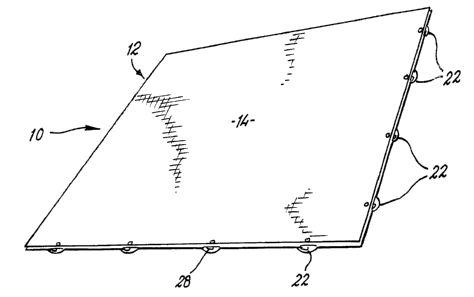
Fig. 1 is a perspective view of a cover assembly component according to
the invention in a first locked condition;
Fig. 2 is a perspective view of the component of Fig. 1 in a second
unlocked condition;
Fig. 3 is a plan view of the component of Fig. 2;
Fig. 4 is a view from beneath of the component of Fig. 2;
Fig. 5 is a side view of the component of Fig. 2;
Fig. 6 is a more detailed view from underneath of part of the component
of Fig. 2;
Fig. 7 is a more detailed view from beneath of a further part of the
component of Fig. 1; and
Fig. 8 is a more detailed cross-sectional view through parts of two
adjacent engaged components according to the invention.
The drawings show a component 10 usable in a cover assembly according
to the invention suitable for instance for temporarily covering an ice rink.
The
component 10 has a generally square configuration with an upper part 12


CA 02364623 2001-08-21
WO 00/59589 PCT/GB00/01227
4
defining an upper surface 14 which can support people or other items thereon.
The surface 14 may have any suitable formations (not shown) thereon to aid the
grip of people walking on the component 10. Such formations may be in the
form of raised chevron shaped formations to create a non-slip surface.
The component 10 also has a lower part 16 which is generally planar
apart from a plurality of spaced upwardly extending frusto conical hollow
projections 18 which extend to meet and support the upper part 12, and a
number of locking recesses (see below). The upper and lower parts 12,18 define
a gap 20 therebetween. Side walls are also provided for the component 10 such
that the gap 20 is substantially sealed apart from a small number of vent
holes
(not shown) which are provided. The projections 18 provide a generally
dimpled effect on the underside of the component 10 (see Figs. 4 and 6). The
gap 20 can be filled with an insulating material such as polyurethane foam, or
with air.
Four spaced locking means 22 (not shown on Fig. 4) are provided on each
of two adjacent sides of the component 10. The locking means 22 comprises a
part circular downwardly open recess 24 in which is pivotally mounted a
locking member 26. The member 26 is arranged to substantially wholly locate
within the recess 24 in a closed position (Fig. 2) but have an arcuate finger
28
thereon extending from the recess 24 when in a locked position (Fig. 1).
Recesses 30 are provided at similar spacings on the other sides of the
component 10. Fig. 8 shows two components 10 with the locking means 22 on
the left hand component 10 engageable with the recess 30 on the right hand
component.
A flange 32 is provided substantially co-planar with the upper surface 14
the two sides of the component 10 which do not have locking means 22. The
flanges 32 ensure that no gap exists between the sides of adjacent components
in use.
The components 10 are formed by twin sheet thermoforming of HDPE
with the upper and lower parts 12,16 integrally formed. The locking members


CA 02364623 2001-08-21
WO 00/59589 PCT/GB00/01227
26 are subsequently pivotally mounted thereon by fingers 34 which rotatably
locate in holes in the upper part 12. The fingers 34 are provided on their
upper
ends which are substantially coplanar with the surface 14, with a recess (not
shown) to permit rotation thereof by a tool, and hence locking or unlocking by
a
person standing on the surface 14.
In use, any required number of components 10 can be mounted together
to cover for instance an ice rink. The adjacent components 10 can readily be
locked together by the locking means 22 by a person standing on or adjacent
the components 10, and using a tool to engage with the fingers 34. The
components 210 can be separated from each other and subsequently removed
in a similar straightforward manner. The provision of the gap 20 filled with
air
or polyurethane foam between the upper and lower parts 12,16, and also
beneath the projections 18, provides for very good insulation from the cold of
the ice. Furthermore, the use of HDPE also provides good insulation. There is
thus described a cover assembly which permits an ice rink or other surface to
readily be covered whilst providing good insulation against the cold ice. The
cover assembly is relatively strong yet can be inexpensively manufactured.
Various modifications may be made without departing from the scope of
the invention. For example different formations could be provided extending
between the upper and lower parts. Different locking means could be used.
The components could be made of different materials and/or a different shape.
Insulating materials other than polyurethane foam, such as other foamed
materials, could be used to fill the gap between the upper and lower parts.
Whilst endeavouring in the foregoing specification to draw attention to
those features of the invention believed to be of particular importance it
should
be understood that the Applicant claims protection in respect of any
patentable
feature or combination of features hereinbefore referred to and/or shown in
the
drawings whether or not particular emphasis has been placed thereon.

Dessin représentatif
Une figure unique qui représente un dessin illustrant l'invention.
États administratifs

Pour une meilleure compréhension de l'état de la demande ou brevet qui figure sur cette page, la rubrique Mise en garde , et les descriptions de Brevet , États administratifs , Taxes périodiques et Historique des paiements devraient être consultées.

États administratifs

Titre Date
Date de délivrance prévu Non disponible
(86) Date de dépôt PCT 2000-03-30
(87) Date de publication PCT 2000-10-12
(85) Entrée nationale 2001-08-21
Demande morte 2005-03-30

Historique d'abandonnement

Date d'abandonnement Raison Reinstatement Date
2003-03-31 Taxe périodique sur la demande impayée 2003-07-14
2004-03-30 Taxe périodique sur la demande impayée

Historique des paiements

Type de taxes Anniversaire Échéance Montant payé Date payée
Enregistrement de documents 100,00 $ 2001-08-21
Le dépôt d'une demande de brevet 150,00 $ 2001-08-21
Taxe de maintien en état - Demande - nouvelle loi 2 2002-04-02 50,00 $ 2001-08-21
Rétablissement: taxe de maintien en état non-payées pour la demande 200,00 $ 2003-07-14
Taxe de maintien en état - Demande - nouvelle loi 3 2003-03-31 100,00 $ 2003-07-14
Titulaires au dossier

Les titulaires actuels et antérieures au dossier sont affichés en ordre alphabétique.

Titulaires actuels au dossier
TERRAPLAS PLC
Titulaires antérieures au dossier
ELSE, ROBERT ARTHUR
Les propriétaires antérieurs qui ne figurent pas dans la liste des « Propriétaires au dossier » apparaîtront dans d'autres documents au dossier.
Documents

Pour visionner les fichiers sélectionnés, entrer le code reCAPTCHA :


Pour visualiser une image, cliquer sur un lien dans la colonne description du document. Pour télécharger l'image (les images), cliquer l'une ou plusieurs cases à cocher dans la première colonne et ensuite cliquer sur le bouton "Télécharger sélection en format PDF (archive Zip)" ou le bouton "Télécharger sélection (en un fichier PDF fusionné)".

Liste des documents de brevet publiés et non publiés sur la BDBC .

Si vous avez des difficultés à accéder au contenu, veuillez communiquer avec le Centre de services à la clientèle au 1-866-997-1936, ou envoyer un courriel au Centre de service à la clientèle de l'OPIC.


Description du
Document 
Date
(yyyy-mm-dd) 
Nombre de pages   Taille de l'image (Ko) 
Page couverture 2002-01-31 1 37
Dessins représentatifs 2002-01-30 1 7
Abrégé 2001-08-21 2 76
Revendications 2001-08-21 4 169
Dessins 2001-08-21 3 45
Description 2001-08-21 5 228
PCT 2001-08-21 13 435
Cession 2001-08-21 4 143
Correspondance 2002-01-29 1 30
Cession 2002-02-15 2 75
Taxes 2003-07-14 1 44